Table of Contents
Advertisement
Quick Links
CAN-USB/400,
CAN-USB/400-IRIG-B,
CAN-USB/400-FD
®
2x CAN (Layer 2, CANopen
, J1939 or ARINC 825)
with optional IRIG-B Input
or 2x CAN FD
Hardware Manual
to Products C.2069.04,
C.2069.06,
C.2069.64
CAN-USB/400 / -IRIG-B / -FD
Hardware Manual • Doc. No.: C.2069.21 / Rev. 1.4
Page 1 of 34
esd electronics gmbh
Vahrenwalder Str. 207 • 30165 Hannover • Germany
http://www.esd.eu
Phone: +49 (0) 511 3 72 98-0 • Fax: +49 (0) 511 3 72 98-68
Advertisement
Table of Contents

Subscribe to Our Youtube Channel
Related Manuals for ESD CAN-USB/400

Summary of Contents for ESD CAN-USB/400
- Page 1 2x CAN FD Hardware Manual to Products C.2069.04, C.2069.06, C.2069.64 CAN-USB/400 / -IRIG-B / -FD Hardware Manual • Doc. No.: C.2069.21 / Rev. 1.4 Page 1 of 34 esd electronics gmbh Vahrenwalder Str. 207 • 30165 Hannover • Germany http://www.esd.eu...
- Page 2 design.
- Page 3 Description of CAN-USB/400-FD inserted New chapter, Description of CAN-USB/400-FD Chapter “Indicator states of CAN LEDs” revised 2018-01-29 New Chapter “CAN FD Interfaces on CAN-USB/400-FD” Chapter “Software Support” revised New Declaration of Conformity inserted Order Information revised Note on CAN FD inserted...
- Page 4 This NOTICE statement contains the general mandatory sign and gives information that must be heeded and complied with for a safe use. INFORMATION INFORMATION Notes to point out something important or useful. Page 4 of 34 Hardware Manual • Doc. No.: C.2069.21 / Rev. 1.4 CAN-USB/400 / -IRIG-B / -FD...
-
Page 5: Safety Instructions
● When working with the CAN-USB/400-Module follow the instructions below and read the manual carefully to protect yourself from injury and the CAN-USB/400-Module from damage. ● Do not use damaged or defective cables to connect the CAN-USB/400-Module and follow the CAN wiring hints in chapter: "Correct Wiring of Electrically Isolated CAN Networks". -
Page 6: Table Of Contents
CAN-USB/400-FD ......................16 4.7.3 Tools........................17 Connector Assignments......................18 5.1 USB............................. 18 CAN0, CAN1........................19 IRIG-B, Trigger and I/Os (CAN-USB/400-IRIG-B only)............20 Correct Wiring of Electrically Isolated CAN Networks..............22 Standards concerning CAN Wiring..................22 Light Industrial Environment (Single Twisted Pair Cable).............23 6.2.1 General Rules...................... - Page 7 Test..................31 Support by esd........................31 Declaration of Conformity......................32 Order Information........................33 Software for CAN-USB/400 and CAN-USB/400-IRIG-B............33 Software for CAN-USB/400-FD....................34 Manuals........................34 CAN-USB/400 / -IRIG-B / -FD Hardware Manual • Doc. No.: C.2069.21 / Rev. 1.4 Page 7 of 34...
-
Page 8: Overview
(esd Advanced CAN Core), implemented in the Altera ® FPGA . Attached to USB via FIFO's and driven by the esdACC, the CAN-USB/400 is designed for minimum latency CAN communication via USB. Advanced diagnostics and high resolution hardware timestamping are supported. -
Page 9: Can-Usb/400-Irig-B
CAN FD (up to 5 Mbit) or CAN 2.0 A/B messages. The CAN FD bit rate range is validated for the esdACC CAN FD core from 10 kbit/s up to 5 Mbit/s. The CAN-USB/400-FD can also be used in Classical CAN Applications, because CAN FD is fully backwards-compatible with CAN. -
Page 10: Case View With Led And Connector Description
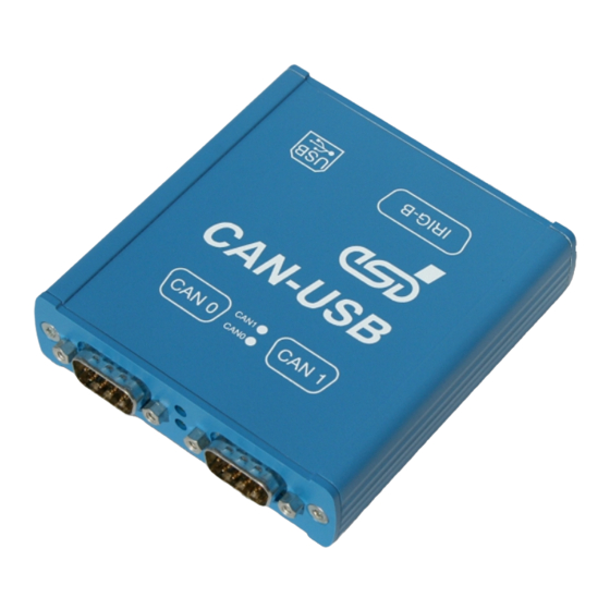
Case View with LED and Connector Description 2. Case View with LED and Connector Description Figure 4: CAN connectors and LEDs (CAN-USB/400-IRIG-B view) Figure 5: USB and IRIG-B (CAN-USB/400-IRIG-B view) See page 18 for signal assignment of the connectors. Page 10 of 34 Hardware Manual •... -
Page 11: Indicator States Of Can Leds
Case View with LED and Connector Description 2.1 Indicator states of CAN LEDs The CAN-USB/400-Modules come with two green CAN LEDs (CAN0, CAN1). See Figure 4 on page 10 for the position of the LEDs. The Special Indicator States are indicated by both LEDs together. -
Page 12: Hardware Installation
In an adapter cable FE (functional earth) shall be connected to the cable shield. Please note that the CAN bus has to be terminated at both ends! esd offers special T-connectors and termination connectors for external termination. Additionally the CAN_GND signal has to be connected to earth at exactly one point in the CAN network. -
Page 13: Technical Data
Table 3: Data of the USB interface 4.3 Local Controller Controller esdACC in FPGA acc. to ISO 898-1 BlockRAM 62 kB Table 4: Controller CAN-USB/400 / -IRIG-B / -FD Hardware Manual • Doc. No.: C.2069.21 / Rev. 1.4 Page 13 of 34... -
Page 14: Can Interfaces On Can-Usb/400(-Irig-B)
Technical Data 4.4 CAN Interfaces on CAN-USB/400(-IRIG-B) INFORMATION The Classical CAN interfaces are equipped on CAN-USB/400 and CAN-USB/400-IRIG-B (C.2069.04, C.2069.06). Number of CAN 2x CAN interfaces esdACC in FPGA Altera ® Cyclone ® CAN controller acc. to ISO 11898-1 (CAN 2.0 A/B) -
Page 15: Interfaces Available At Can-Usb/400-Irig-B Only
Technical Data 4.6 Interfaces available at CAN-USB/400-IRIG-B only INFORMATION The IRIG-B option is only available on CAN-USB/400-IRIG-B (C.2069.06). 4.6.1 IRIG-B Interface Number of inputs 1x analog (IRIG-B_RX+, IRIG-B_RX-) 1x digital (IRIG-B_A+, IRIG-B_A-) Standard IRIG-B inputs acc. to standard 200-87, format B122 (analog) and B003 (digital) -
Page 16: Microcontroller For Irig-B
“NTCAN-API Part 2: Installation, Configuration and Firmware Update” Installation Guide esd-order No.: C.2001.21 4.7.1 CAN-USB/400(-IRIG-B) The CAN-USB/400 and the CAN-USB/400-IRIG-B support the CAN layer 2 API (NTCAN) for Windows ® . The CAN layer 2 drivers for Windows are included in the scope of delivery. -
Page 17: Can Tools
- 30 MB free HD drive space - esd CAN driver installed As part of the esd software development kit (CAN SDK) of the NTCAN-API the CAN Tools are included in delivery of the CAN-CD. The CAN SDK can also be downloaded free-of-charge from the esd website. -
Page 18: Connector Assignments
... connector housings of CAN0, CAN1, USB and (if applicable) IRIG-B are connected to each other and via 10 nF to both CAN_GNDs of CAN0 and CAN1 Page 18 of 34 Hardware Manual • Doc. No.: C.2069.21 / Rev. 1.4 CAN-USB/400 / -IRIG-B / -FD... -
Page 19: Can0, Can1
... connector housings of CAN0, CAN1, USB and (if applicable) IRIG-B are connected to each other and via 10 nF to both CAN_GNDs of CAN0 and CAN1 CAN-USB/400 / -IRIG-B / -FD Hardware Manual • Doc. No.: C.2069.21 / Rev. 1.4 Page 19 of 34... -
Page 20: Irig-B, Trigger And I/Os (Can-Usb/400-Irig-B Only)
Connector Assignments 5.3 IRIG-B, Trigger and I/Os (CAN-USB/400-IRIG-B only) INFORMATION The IRIG-B, Trigger and I/O-option is only available on CAN-USB/400-IRIG-B (C.2069.06). Device connector: 15-pin DSUB connector, female Pin Position: Pin Assignment: Signal Signal TRIG0 TRIG1 TRIG2 TRIG3 TRIG4 TRIG5 SYNC1-... - Page 21 Connector Assignments Wiring of the analog and the digital IRIG-B interface at DSUB15 Figure 6: IRIG-B wiring guidelines CAN-USB/400 / -IRIG-B / -FD Hardware Manual • Doc. No.: C.2069.21 / Rev. 1.4 Page 21 of 34...
-
Page 22: Correct Wiring Of Electrically Isolated Can Networks
Therefore the practical maximum number of nodes, bus length and stub length are typically much lower. esd has concentrated her recommendations concerning CAN wiring on the specifications of the ISO 11898-2. Thus this wiring hints forgoes to describe the special features of the derived standards CANopen, ARINC825, DeviceNet and NMEA2000. -
Page 23: Light Industrial Environment (Single Twisted Pair Cable)
6.2.1 General Rules NOTICE esd grants the EU Conformity of the product, if the CAN wiring is carried out with at least single shielded single twisted pair cables that match the requirements of ISO 11898-2. Single shielded double twisted pair cable wiring as described in chapter 6.3. ensures the EU Conformity as well. -
Page 24: Cabling
9-pin DSUB-termination connectors with integrated termination resistor and male and ● female contacts are available from esd (order no. C.1303.01). DSUB termination connectors with male contacts (order no. C.1302.01) or female contacts ● (order no. C.1301.01) and additional functional earth contact are available, if CAN termination and grounding of CAN_GND is required. -
Page 25: Heavy Industrial Environment (Double Twisted Pair Cable)
Shield n.c. = not connected earth (FE) Figure 9: CAN wiring for heavy industrial environment CAN-USB/400 / -IRIG-B / -FD Hardware Manual • Doc. No.: C.2069.21 / Rev. 1.4 Page 25 of 34... -
Page 26: Device Cabling
CAN bus line via short cable stubs. This is normally realised by so called T- connectors. When using esd's CAN-T-Connector (order no.: C.1311.03) it should be noted that the shield potential of the conductive DSUB housing is not looped through this T- Connector type. -
Page 27: Electrical Grounding
5000 Table 11: Recommended cable lengths at typical bit rates (with esd-CAN interfaces) Optical couplers are delaying the CAN signals. esd modules typically reach a wire length of ● 37 m at 1 Mbit/s within a proper terminated CAN network without impedance disturbances like e.g. -
Page 28: Examples For Can Cables
Correct Wiring of Electrically Isolated CAN Networks 6.6 Examples for CAN Cables esd recommends the following two-wire and four-wire cable types for CAN network design. These cable types are used by esd for ready-made CAN cables, too. 6.6.1 Cable for light industrial Environment Applications (Two-Wire) -
Page 29: Can Troubleshooting Guide
- there are no open circuits in CAN_H or CAN_L wiring - your bus system has two terminating resistors (one at each end) and that they are 120 Ω each. CAN-USB/400 / -IRIG-B / -FD Hardware Manual • Doc. No.: C.2069.21 / Rev. 1.4 Page 29 of 34... -
Page 30: Electrical Grounding
4. Measure the DC voltage between CAN_L and CAN_GND (see figure at previous page). Normally the voltage should be between 2.0 V and 3.0 V. Page 30 of 34 Hardware Manual • Doc. No.: C.2069.21 / Rev. 1.4 CAN-USB/400 / -IRIG-B / -FD... -
Page 31: Can Transceiver Resistance Test
If you have executed the fault diagnostic steps of this troubleshooting guide and you even can not find a solution for your problem our support department will be able to assist. Please contact our support via email at support@esd.eu or by phone +49-511-37298-130. CAN-USB/400 / -IRIG-B / -FD Hardware Manual •... -
Page 32: Declaration Of Conformity
Declaration of Conformity 8. Declaration of Conformity Page 32 of 34 Hardware Manual • Doc. No.: C.2069.21 / Rev. 1.4 CAN-USB/400 / -IRIG-B / -FD... -
Page 33: Order Information
9.1 Software for CAN-USB/400 and CAN-USB/400-IRIG-B Type Order No. CAN layer 2 software drivers for Windows on CD-ROM to CAN-USB/400 (C.2069.04) and CAN-USB/400-IRIG-B (C.2069.06) are included in delivery. Higher-Layer Protocols including CD-ROM (Classical CAN Applications only): CANopen Object Driver Licence + CD-ROM for Windows CANopen-LCD Windows/Linux C.1101.06... -
Page 34: Software For Can-Usb/400-Fd
Order Information 9.2 Software for CAN-USB/400-FD Type Order No. CAN layer 2 software drivers for Windows and Linux on CD-ROM to CAN-USB/400-FD (C.2069.64) are included in delivery. Higher-Layer Protocols including CD-ROM for Classical CAN Applications: CANopen-LCD Windows/Linux C.1101.06 These Windows drivers are...
Need help?
Do you have a question about the CAN-USB/400 and is the answer not in the manual?
Questions and answers