
Related Manuals for Grip Rite GR55G10X


Summary of Contents for Grip Rite GR55G10X
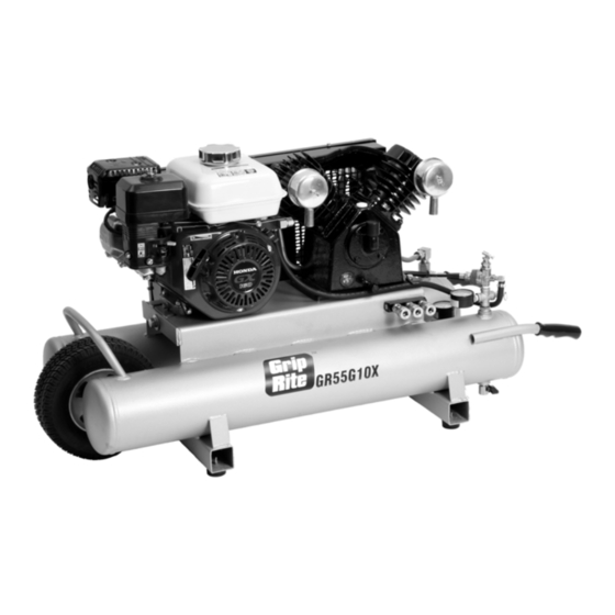
- Page 1 OPERATING MANUAL AND PARTS LIST MODEL GR55G10X/GR90G10X COMPRESSORS www.grip-rite.com...
-
Page 2: Table Of Contents
Compressor Description .............. 6 Compressor Parts Description............. 7 Set Up..................... 8 Operation ..................9 Maintenance ................10 GR55G10X Compressor Schematics and Parts Lists ....12 GR90G10X Compressor Schematics and Parts Lists ....17 Troubleshooting ................22 Storage..................25 Warranty..................26 WARNING This manual contains important safety and operating instructions that must be followed. -
Page 3: Safety Symbols
SAFETY SYMBOLS The safety symbols used on the compressor’s safety labels and in this manual provide an important visual reminder of basic safety rules, and the hazards that may arise if all safety and operating instructions are not followed. Make sure you understand the meaning of each of these symbols, and protect yourself and others by obeying all safety and operating instructions on warning labels and in this manual. -
Page 4: Safety Instructions
SAFETY INSTRUCTIONS WEAR ANSI Z87.1 (In Canada, CSA Z94.3-99) APPROVED EYE PROTECTION - Always wear approved eye protection equipment that provides both front and side eye protection when operating or servicing the compressor. DO NOT START OR OPERATE COMPRESSOR INDOORS OR IN POORLY VENTILATED AREAS - Gasoline engine produce carbon monoxide, a poisonous gas that can cause death or serious injury if inhaled. - Page 5 SAFETY INSTRUCTIONS DO NOT TAMPER WITH COMPRESSOR PRESSURE SWITCH SETTINGS - The pressure switch settings set at the factory provide the maximum safe operating pressure recommended for this compressor. Altering these settings can result in over-pressurization, risk of tank, hose, and pneumatic equipment failure, and serious injury to operator and bystanders. USE AIR HOSE RATED FOR 150 PSI OR GREATER - Air hose must be rated to safely handle maximum compressor pressure.
-
Page 6: Specifications
SPECIFICATIONS DESCRIPTION SPECIFICATIONS Motor GR55G10X GR90G10X Horsepower Engine Honda GX160 Honda GX270 Capacity Tanks Air Storage Capacity 10 Gallons 10 Gallons Maximum Air Pressure 135 PSI 135 PSI 12.5 cfm @ 100 PSI 18.5 cfm @ 100 PSI Pressure Switch Settings... -
Page 7: Compressor Description
COMPRESSOR DESCRIPTION... -
Page 8: Compressor Parts Description
COMPRESSOR PARTS DESCRIPTION DESCRIPTION FUNCTION Belt Guard Guards V-belt and pulleys Compressor Pump Compresses air Compressor Air Intake Contains air filter element Crankcase breather/fill plug Used to vent/fill pump crankcase Pilot Valve Controls engine throttle Tank Air Pressure Gauge Indicates air pressure in storage tanks Rubber Hand Grips Provides secure grip for comfortable handling Tank Drain Cock... -
Page 9: Set Up
SET UP PROCEDURE WARNING: Before being operated with pressurized tanks for the first time, your new compressor requires a simple set-up procedure that will help your unit deliver years of trouble-free service. Failure to follow all initial set-up instructions may result in serious damage to your compressor, property damage, or serious injury to operator and bystanders. -
Page 10: Operation
OPERATION STARTING ENGINE Pre-starting Checklist: Always check and correct before starting: Check unit for missing parts or damage. Check for loose nuts and bolts. Check compressor and engine oil levels. Fill gas tank. Tighten gas cap securely. ... -
Page 11: Maintenance
OPERATION NORMAL OPERATION Engine runs at normal running speed until maximum tank air pressure is reached. When maximum pressure is reached, engine speed automatically resets to idle. Engine speed remains at idle until tank pressure drops to the minimum air pressure setting. Engine continues cycling between normal and idle speed automatically until turned off. - Page 12 MAINTENANCE Maintenance Schedule COMPRESSOR MAINTENANCE CHART Interval Maintenance Required Check compressor pump and engine lubricant levels, and fill as needed. Drain moisture from tanks daily. Open drain slowly and let air pressure bleed down gradually before opening drain valve completely. Daily Perform a visual inspection of compressor.
-
Page 13: Gr55G10X Compressor Schematics And Parts Lists
GR55G10X COMPRESSOR SCHEMATIC- TANK / FRAME... - Page 14 GR55G10X COMPRESSOR PARTS LIST- TANK / FRAME REF NO. DESCRIPTION QTY. PART # Screw GRCE1490 Belt Guard Cover GRCE1160 Belt Guard Base GRCE1140 Belt GRCE1340 Bolt GRCE1630 Washer GRCE1640 Flywheel GRCE1800 Complete Pump with Flywheel GRCE840 Delivery Tube with Fittings...
- Page 15 GR55G10X COMPRESSOR PARTS LIST- TANK / FRAME REF NO. DESCRIPTION QTY. PART # Hose Barb GRCE1250 Washer -1/2" GRCE2230 Handle Grip GRCE1050 Drain Valve GRCE1070 Triple Manifold GRCE1450 Quick Coupler GRCE1390 Tank Assembly GRCE1600 Rubber Pad GRCE1040 Screw GRCE1460 Cotter Pin...
- Page 16 GR55G10X COMPRESSOR PARTS LIST - PUMP...
- Page 17 GR55G10X COMPRESSOR PARTS LIST - PUMP REF # PART # DESCRIPTION Intake Filter Assembly GRCE130 Intake Element GRCE50 Cylinder Head GRCE520 Gasket GRCE570 Gasket GRCE560 Triangle Valve Spring GRCE1660 Lift Limiter GRCE210 Inlet Valve GRCE550 Outlet Valve GRCE1670 Lock Screws (not shown)
-
Page 18: Gr90G10X Compressor Schematics And Parts Lists
GR90G10X COMPRESSOR SCHEMATIC- TANK / FRAME... - Page 19 GR90G10X COMPRESSOR PARTS LIST - TANK/FRAME REF NO. DESCRIPTION QTY. PART # Screw GRCE1490 Belt Guard Cover GRCE1170 Belt Guard Base GRCE1150 Belt GRCE1350 Bolt GRCE1630 Washer GRCE1640 Flywheel GRCE1650 Complete Pump with Flywheel GRCE850 Delivery Tube with Fittings GRCE1430 Elbow GRCE1290 Check Valve...
- Page 20 GR90G10X COMPRESSOR PARTS LIST - TANK/FRAME REF NO. DESCRIPTION QTY. PART # Hose Barb GRCE1250 Washer -1/2" GRCE2230 Handle Grip GRCE1050 Drain Valve GRCE1070 Triple Manifold GRCE1450 Quick Coupler GRCE1390 Tank Assembly GRCE1610 Rubber Pad GRCE1040 Screw GRCE1460 Cotter Pin GRCE1110 Machine Bushing GRCE1520...
- Page 21 GR90G10X COMPRESSOR SCHEMATIC - PUMP...
- Page 22 GR90G10X COMPRESSOR PARTS LIST - PUMP REF # PART # DESCRIPTION Intake Filter Assembly GRCE130 Intake Element GRCE50 Cylinder Head GRCE520 Gasket GRCE570 Gasket GRCE560 Triangle Valve Spring GRCE1660 Lift Limiter GRCE210 Inlet Valve GRCE550 Outlet Valve GRCE1670 Lock Screws (not shown) GRCE1680 Valve Plate Assembly GRCE1690...
-
Page 23: Troubleshooting
TROUBLESHOOTING PROBLEM CAUSE REMEDY Compressor won't start On/Off switch in OFF position Move switch to ON position Fuel Switch in OFF position Move switch to ON position Choke lever in Open Choke Move lever to Closed choke (running) position (starting) position Fuel tank empty Fill fuel tank Spark plug fouled... - Page 24 TROUBLESHOOTING PROBLEM CAUSE REMEDY Compressor Loads/Unloads or Leaks in air system Replace worn parts as necessary Starts/Stops excessively Worn or loose drive belts Tighten or replace belts as necessary. Pilot valve or pressure switch Have adjustments made by differential adjusted too close authorized service location Compressor valves not operating Replace valves...
- Page 25 TROUBLESHOOTING PROBLEM CAUSE REMEDY Excessive vibration Loose compressor or motor Tighten mounting bolts Excessive discharge pressure Reduce operating pressure Compressor not level Level compressor Leg bolt tightened too tight Loose leg bolts Wrong oil being used Drain and replace with proper oil Loose flywheel, drive pulley, or drive Tighten parts and check belt belt...
-
Page 26: Storage
TROUBLESHOOTING PROBLEM CAUSE REMEDY Tool, sprayer, or other accessory Air pressure too low or too high Adjust regulator to provide doesn't work properly. pressure recommended by product manufacturer. Unit runs continuously Air usage greater than compressor Check CFM requirements of air output capacity tool or accessory being used. -
Page 27: Warranty
BUILDING PRODUCTS CANADA CORPORATION Are Itochu Companies PNEUMATIC TOOL/COMPRESSOR WARRANTY Pneumatic nailers, staplers & compressors marketed under the GRIP RITE brand are warranted to be free from defects in workmanship & materials (except rubber o-rings, bumpers, seals, driver blades, dipsticks, & air filters) for a period of one year from the date of original purchase. - Page 28 GRGASMAN 03/09...
Need help?
Do you have a question about the GR55G10X and is the answer not in the manual?
Questions and answers