Advertisement
Table of Contents
- 1 Table of Contents
- 2 Safety Symbols
- 3 Safety Instructions
- 4 Specifications
- 5 Compressor Description
- 6 Compressor Parts Description
- 7 Set up
- 8 Operation
- 9 Maintenance
- 10 Compressor Schematic
- 11 Compressor Parts List - Pump
- 12 Compressor Parts List -Tank/Frame
- 13 Troubleshooting
- 14 Storage
- 15 Warranty
- Download this manual
Advertisement
Table of Contents

Related Manuals for Grip Rite GR2540


Summary of Contents for Grip Rite GR2540
- Page 1 OPERATING MANUAL AND PARTS LIST MODEL GR2540 COMPRESSOR Because quality work demands quality tools...
-
Page 2: Table Of Contents
TABLE OF CONTENTS Table of Contents ................1 Safety Symbols ................2 Safety Instructions................ 3 Specifications................5 Compressor Description .............. 6 Compressor Parts Description............. 7 Set Up..................... 8 Operation ..................10 Maintenance ................11 Compressor Schematic .............. 12 Compressor Parts List - Pump........... 13 Compressor Parts List -Tank/Frame.......... -
Page 3: Safety Symbols
SAFETY SYMBOLS The safety symbols used on the compressor’s safety labels and in this manual provide an important visual reminder of basic safety rules, and the hazards that may arise if all safety and operating instructions are not followed. Make sure you understand the meaning of each of these symbols, and protect yourself and others by obeying all safety and operating instructions on warning labels and in this manual. -
Page 4: Safety Instructions
SAFETY INSTRUCTIONS WEAR ANSI Z87.1 APPROVED EYE PROTECTION - Always wear approved eye protection equipment that provides both front and side eye protection when operating or servicing the compressor. DO NOT EXCEED MAXIMUM RECOMMENDED OPERATING PRESSURE OF AIR-POWERED TOOLS OR OTHER EQUIPMENT BEING USED - Spray guns and other low to medium pressure equipment can burst, causing serious injury to user and bystanders. - Page 5 SAFETY INSTRUCTIONS NEVER DIRECT COMPRESSED AIR AT ANY BODY PARTS - Compressed air can penetrate skin, or force dirt and debris into eyes, causing serious injury. Never place hands or body parts over the air discharge opening of a pressurized nozzle or fitting. Use care when connecting and disconnecting air hose to attachments, pneumatic tools, and other air-powered devices.
-
Page 6: Specifications
SPECIFICATIONS DESCRIPTION SPECIFICATION Motor Horsepower 2.5 (Peak) Voltage 115V Amperage Phase Single 3450 Capacity Tanks Air Storage Capacity 4 Gallons Maximum Air Pressure 150 PSI 5.7 cfm @ 40 PSI 4.5 cfm @ 90 PSI Pressure Switch Settings Pressure Switch - ON 110 PSI Pressure Switch - OFF 150 PSI... -
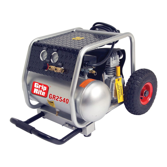
Page 7: Compressor Description
COMPRESSOR DESCRIPTION... -
Page 8: Compressor Parts Description
COMPRESSOR PARTS DESCRIPTION DESCRIPTION FUNCTION Heavy Duty Power Cord Provides power to compressor motor Frame Protects compressor components Compressor Pump Compresses air Reset Switch Protects motor from overloads Dipstick Used to check oil level in pump crankcase Hex Head Wheel Bolt Secures wheels to compressor frame Wheel Assembly Large pneumatic tires allow easy rolling... -
Page 9: Set Up
SET UP WARNING: Before being used for the first time, your new compressor requires a simple set-up procedure that will help your unit deliver years of trouble-free service. Failure to follow all initial set-up instructions may result in serious damage to your compressor, property damage, or serious injury to operator and bystanders. - Page 10 4. Install dipstick in crankcase, and tighten securely before starting compressor. Make sure black seal is in place between dipstick and crankcase to prevent loss of oil during compressor operation or movement. 5. Check power outlet circuit for correct capacity. Compressor requires 120V, Single Phase, 14 Amps, 60 Hz.
-
Page 11: Operation
OPERATION Operating Compressor 1. Move On/Off lever to the "OFF" position. 2. Plug the power cord into the power receptacle. 3. Move On/Off lever to the "ON" position. 4. Leave compressor in “ON” position while in use. 5. To stop compressor, move On/Off lever to the "OFF"... -
Page 12: Maintenance
MAINTENANCE Maintenance Schedule DANGER Never perform maintenance on the compressor when it is in the “ON” position. Always place On/Off switch in “OFF” position, disconnect power cord from power source, drain air tanks, and allow unit to cool first. Performing service procedures on a compressor with pressurized tanks, or in the “ON”... -
Page 13: Compressor Schematic
COMPRESSOR SCHEMATIC PUMP TANK/FRAME... -
Page 14: Compressor Parts List - Pump
COMPRESSOR PARTS LIST - PUMP REF NO. DESCRIPTION QTY. PART# CYLINDER HEAD PACP408 ALLEN BOLT PACP396 SPRING WASHER PACP3 AIR FILTER PACP409 FILTER ELEMENT PACP410 CYLINDER HEAD GASKET PACP9 IN. & EX. VALVE ASSEMBLY PACP82 VALVE SEAT GASKET PACP411 CYLINDER PACP412 HEXAGON NUT PACP20... -
Page 15: Compressor Parts List -Tank/Frame
COMPRESSOR PARTS LIST - TANK/FRAME REF NO. DESCRIPTION QTY. PART# AIR TANK PACP429 TANK WHEEL PACP430 TANK WHEEL BOLT PACP431 RUBBER PAD PACP432 PLATE WASHER PACP45 HEXAGON BOLT PACP42 DRAIN VALVE PACP35 GRIP SET PACP433 CHECK VALVE PACP434 TUBE PACP435 UNLOADING ELBOW PACP48 UNLOADING TUBE... -
Page 16: Troubleshooting
TROUBLESHOOTING PROBLEM CAUSE REMEDY Compressor won't start Circuit breaker tripped Reset breaker Fuse blown in power supply branch Replace fuse. Use Fusetron circuit. type “T” fuse only. Power turned off. Turn power on Pressure release valve on Bleed line by moving switch to motor/pressure switch has not “OFF”... - Page 17 TROUBLESHOOTING PROBLEM CAUSE REMEDY Air leaks at fittings Fittings loose Tighten fittings Air leaks at compressor head Head bolts loose Tighten bolts securely Air blows out of inlet filter Damaged reed valve Have unit serviced by authorized service dealer Insufficient pressure at air tool or Air intake filter dirty Clean or replace filter accessory...
-
Page 18: Storage
STORAGE Open tank drain valve and allow all air pressure to escape. Drain all moisture out of tanks, and close drain valves. Disconnect air hose and wind hose carefully for storage Inspect compressor for wear, damage, or missing parts, and have repairs made promptly. -
Page 19: Warranty
BUILDING PRODUCTS CANADA CORPORATION Are Itochu Companies PNEUMATIC TOOL/COMPRESSOR WARRANTY Pneumatic nailers, staplers & compressors marketed under the GRIP RITE brand are warranted to be free from defects in workmanship & materials (except rubber o-rings, bumpers, seals, driver blades, dipsticks, &... - Page 20 GR2540MAN...
Need help?
Do you have a question about the GR2540 and is the answer not in the manual?
Questions and answers