Chapters
Table of Contents

Subscribe to Our Youtube Channel
Related Manuals for Grip Rite GR254CTS


Summary of Contents for Grip Rite GR254CTS
- Page 1 OPERATING MANUAL AND PARTS LIST MODEL GR254CTS COMPRESSOR Because quality work demands quality tools Distributed By RIME OURCE ® BUILDING PRODUCTS, INC An Itochu Company (800) 676-7777...
-
Page 2: Table Of Contents
TABLE OF CONTENTS Table of Contents ................1 Safety Symbols ................2 Safety Instructions................ 3 Specifications................5 Compressor Description .............. 6 Compressor Parts Description............. 7 Set Up..................... 8 Operation ..................9 Maintenance ................10 Compressor Pump Schematic ........... 11 Compressor Pump Parts List ............. 12 Compressor Tank Schematic ............. -
Page 3: Safety Symbols
SAFETY SYMBOLS The safety symbols used on the compressor’s safety labels and in this manual provide an important visual reminder of basic safety rules, and the hazards that may arise if all safety and operating instructions are not followed. Make sure you understand the meaning of each of these symbols, and protect yourself and others by obeying all safety and operating instructions on warning labels and in this manual. -
Page 4: Safety Instructions
SAFETY INSTRUCTIONS WEAR ANSI Z87.1 APPROVED EYE PROTECTION - Always wear approved eye protection equipment that provides both front and side eye protection when operating or servicing the compressor. DO NOT EXCEED MAXIMUM RECOMMENDED OPERATING PRESSURE OF AIR-POWERED TOOLS OR OTHER EQUIPMENT BEING USED - Spray guns and other low to medium pressure equipment can burst, causing serious injury to user and bystanders. - Page 5 SAFETY INSTRUCTIONS NEVER DIRECT COMPRESSED AIR AT ANY BODY PARTS - Compressed air can penetrate skin, or force dirt and debris into eyes, causing serious injury. Never place hands or body parts over the air discharge opening of a pressurized nozzle or fitting. Use care when connecting and disconnecting air hose to attachments, pneumatic tools, and other air-powered devices.
-
Page 6: Specifications
SPECIFICATIONS DESCRIPTION SPECIFICATION Motor Horsepower 2.5(Peak) Voltage Amperage Phase Single 3450 Capacity Tanks Air Storage Capacity 4.3 Gallons Maximum Air Pressure 125 PSI 4.1 cfm @ 90 PSI 4 cfm @ 100 PSI Pressure Switch Settings Pressure Switch - ON 95 PSI Pressure Switch - OFF 125 PSI... -
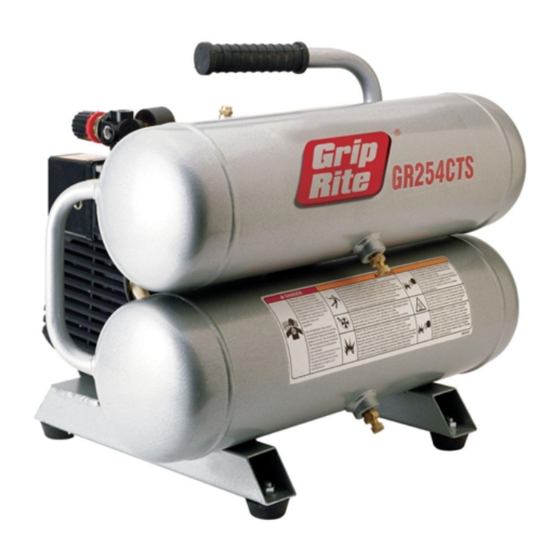
Page 7: Compressor Description
COMPRESSOR DESCRIPTION GR254CTS... -
Page 8: Compressor Parts Description
COMPRESSOR PARTS DESCRIPTION DESCRIPTION FUNCTION Handle Used to lift, carry, and position unit. Air Tank Drain Allows moisture to be drained from tanks Rubber Foot Provides stable footing, reduces vibration Air Storage Tank Stores compressed air Cooling System Cools compressor components Safety Relief Valve Releases excessive air pressure Air Outlet Fitting... -
Page 9: Set Up
SET UP Before being used for the first time, your new compressor requires a simple set-up procedure that will help your unit deliver years of trouble-free service. WARNING: Failure to follow all initial set-up instructions may result in serious damage to your compressor, property damage, or serious injury to operator and bystanders. -
Page 10: Operation
OPERATION Starting Compressor 1. Push On/Off button to the "OFF" position. 2. Plug the power cord into the power receptacle. 2. Pull On/Off button to the "ON" position. 3. Leave compressor in “ON” position while in use. 4. To stop compressor, push On/Off button to the "OFF" position. -
Page 11: Maintenance
Clean or replace air filter element. Change crankcase lubricant. Yearly Check tanks for cracks, corrosion, leaks, or other damage. Never use a compressor with a damaged tank. Check warning labels for legibility, and replace if necessary. Contact your Grip-Rite dealer for replacement labels. -
Page 12: Compressor Pump Schematic
COMPRESSOR SCHEMATIC - PUMP... -
Page 13: Compressor Pump Parts List
COMPRESSOR PARTS LIST - PUMP DESCRIPTION QTY. PART# Head Bolt GRFC12 Head GRFC32 Intake filter GRFC58 Head Gasket GRFC34 Valve Plate GRFC38 Gasket GRFC35 Reed Valve GRFC39 Valve Plate Gasket GRFC37 Cylinder GRFC47 Bolt GRFC17 Gasket GRFC44 Comp. Piston Assy GRFC67 Ring Set GRFC56... -
Page 14: Compressor Tank Schematic
COMPRESSOR PARTS LIST - PUMP DESCRIPTION QTY. PART# Bearing GRFC26 End Bell GRFC30 GRFC29 Thru-Bolt GRFC31 Shroud GRFC48 Washer GRFC15 Screw GRFC16 Gasket Set - Includes parts: GRFC4, GRFC34, GRFC57 GRFC35, GRFC43, GRFC44 COMPRESSOR SCHEMATIC - TANK... -
Page 15: Compressor Tank Parts List
COMPRESSOR PARTS LIST - TANK DESCRIPTION QTY. PART# Tank Assembly GRFC50 Drain cock GRFC24 Handle Grip GRFC49 Mounting Plate GRFC52 Screw GRFC10 GRFC13 Vibration Damper GRFC53 Screw GRFC20 Nut for Rubber Feet GRFC14 Rubber Foot GRFC23 Check Valve GRFC63 Nylon Tubing GRFC27 Discharge Tube GRFC55... -
Page 16: Troubleshooting
TROUBLESHOOTING PROBLEM CAUSE REMEDY Compressor won't start Circuit breaker tripped Reset breaker Fuse blown Replace fuse. Use Fusetron type “T” fuse only. Power turned off. Turn power on Pressure release valve on Bleed line by moving switch to motor/pressure switch has not “OFF”... - Page 17 TROUBLESHOOTING PROBLEM CAUSE REMEDY Air leaks at fittings Fittings loose Tighten fittings Air leaks at compressor head Head bolts loose Tighten bolts securely Air blows out of inlet filter Damaged reed valve Have unit serviced by authorized service dealer Insufficient pressure at air tool or Air intake filter dirty Clean or replace filter accessory...
-
Page 18: Maintenance Procedures
MAINTENANCE PROCEDURES Check safety valve Check/clean air filter Drain water from tanks Check oil level STORAGE ! Open tank drain valve and allow all air pressure to escape. ! Drain all moisture out of tanks, and close drain valves. ! Disconnect air hose and wind hose carefully for storage ! Inspect compressor for wear, damage, or missing parts, and have repairs made promptly. -
Page 19: Warranty
Repairs are required due to normal wear & tear • The tool/compressor has been inadequately packaged leading to damage in-transit to the service/warranty center *Approved fasteners include the following brands GRIP-RITE FAS’NERS , FAS’NERS UNLIMITED ® IN NO EVENT SHALL PRIMESOURCE BE LIABLE FOR ANY INDIRECT, ACCIDENTAL OR CONSEQUENTAL DAMAGE FROM THE SALE OR USE OF THESE PRODUCTS. - Page 20 RIME OURCE ® BUILDING PRODUCTS, INC An Itochu Company...
- Page 21 MANUAL DE OPERACIÓN Y LISTA DE PIEZAS COMPRESOR MODELO GR254CTS Porque el trabajo de calidad requiere herramientas de calidad Distribuido por RIME OURCE ® BUILDING PRODUCTS, INC Una compañía Itochu (800) 676-7777...
-
Page 22: Índice
ÍNDICE Índice .................... 1 Símbolos de seguridad ..............2 Instrucciones de seguridad............3 Especificaciones ................5 Descripción del compresor ............6 Descripción de las piezas del compresor........7 Configuración................8 Operación..................9 Mantenimiento ................10 Esquema de la bomba del compresor ........ -
Page 23: Símbolos De Seguridad
SÍMBOLOS DE SEGURIDAD Los símbolos de seguridad usados en las etiquetas de seguridad del compresor y en este manual constituyen un recuerdo visual importante de las reglas de seguridad básicas y de los peligros que pueden surgir si no se respetan todas las instrucciones de seguridad y operación. -
Page 24: Instrucciones De Seguridad
INSTRUCCIONES DE SEGURIDAD LLEVE PUESTOS PROTECTORES PARA LOS OJOS APROBADOS POR ANSI Z87.1 – Lleve siempre equipos aprobados para la protección de los ojos tanto delanteros como laterales para hacer funcionar el compresor o efectuar el servicio del mismo. NO EXCEDA LA PRESIÓN DE OPERACIÓN MÁXIMA RECOMENDADA DE HERRAMIENTAS NEUMÁTICAS U OTROS EQUIPOS USADOS –... - Page 25 INSTRUCCIONES DE SEGURIDAD NO DIRIJA NUNCA AIRE COMPRIMIDO A NINGUNA PARTE DEL CUERPO - El aire comprimido puede penetrar la piel o forzar la suciedad y los residuos dentro de ojos, ocasionando lesiones graves. No coloque nunca las manos ni las partes del cuerpo sobre la abertura de descarga de aire de una boquilla o conexión a presión.
-
Page 26: Especificaciones
ESPECIFICACIONES DESCRIPCIÓN ESPECIFICACIÓN Motor Potencia 2.5 hp (máxima) Voltaje Amperaje Fase Monofásica 3450 Capacidad Depósitos Capacidad de almacenamiento de aire 4.3 galones (16.3 litros) Presión de aire máxima 125 lb/pulg (8.6 bares) /MIN 4.1 pie /min a 90 lb/pulg 4 pie /min a 100 lb/pulg Ajustes del interruptor de presión Interruptor de presión - ENCENDIDO... -
Page 27: Descripción Del Compresor
DESCRIPCIÓN DEL COMPRESOR GR254CTS... -
Page 28: Descripción De Las Piezas Del Compresor
DESCRIPCIÓN DE LAS PIEZAS DEL COMPRESOR CLAVE DESCRIPCIÓN FUNCIÓN Se usa para levantar, llevar y colocar la unidad. Desagüe del depósito de aire Permite vaciar fluido de los depósitos Apoyo de goma Proporciona estabilidad, reduce las vibraciones Depósito de almacenamiento de aire Almacena aire comprimido Sistema de enfriamiento Enfría los componentes del compresor... -
Page 29: Configuración
CONFIGURACIÓN Antes de usarse por primera vez, el nuevo compresor requiere un procedimiento de configuración sencillo que permitirá que la unidad funcione a buen rendimiento y sin problemas durante años. ADVERTENCIA: De no seguir todas las instrucciones de configuración iniciales, se pueden producir daños importantes en el compresor, daños materiales o el operador o las personas de los alrededores pueden resultar gravemente lesionadas. -
Page 30: Operación
OPERACIÓN Arranque del compresor 1. Ponga el botón de encendido/apagado en la posición “OFF”. 2. Enchufe el cordón de alimentación a la toma de corriente. 3. Ponga el botón de encendido/apagado en la posición “ON”. 4. Deje el compresor en la posición “ON” mientras se usa. 5. -
Page 31: Mantenimiento
Compruebe el cordón de alimentación del compresor y el enchufe para ver si están dañados. No use el compresor si el cordón o el enchufe está dañado. Póngase en contacto con su distribuidor Grip-Rite para cuestiones de servicio. Semanalmente Compruebe la válvula de alivio de presión para ver si funciona de forma apropiada. -
Page 32: Esquema De La Bomba Del Compresor
ESQUEMA DEL COMPRESOR - BOMBA... -
Page 33: Lista De Piezas De La Bomba Del Compresor
LISTA DE PIEZAS DEL COMPRESOR - BOMBA N° DE REF. DESCRIPCIÓN CDAD. N°DE PIEZA Perno de cabeza GRFC12 Cabeza GRFC32 Filtro de entrada GRFC58 Empaquetadura de la cabeza GRFC34 Placa de la válvula GRFC38 Empaquetadura GRFC35 Válvula Reed GRFC39 Empaquetadura de la placa de la válvula GRFC37 Cilindro GRFC47... -
Page 34: Esquema De Los Depósitos Del Compresor
LISTA DE PIEZAS DEL COMPRESOR - BOMBA N° DE REF. DESCRIPCIÓN CDAD. N° DE PIEZA Cojinete GRFC26 Cubierta de extremo GRFC30 Ventilador GRFC29 Perno pasante GRFC31 Envuelta GRFC48 Arandela GRFC15 Tornillo GRFC16 Juego de empaquetaduras – incluye las piezas siguientes: GRFC4, GRFC34, GRFC35, GRFC57 GRFC43, GRFC44 ESQUEMA DEL COMPRESOR - DEPÓSITOS... -
Page 35: Lista De Piezas De Los Depósitos Del Compresor
LISTA DE PIEZAS DEL COMPRESOR - DEPÓSITOS N° DE REF. DESCRIPCIÓN CDAD. N° DE PIEZA Conjunto de depósito GRFC50 Llave de desagüe GRFC24 Empuñadura GRFC49 Placa de montaje GRFC52 Tornillo GRFC10 Tuerca GRFC13 Amortiguador de vibraciones GRFC53 Tornillo GRFC20 Tuerca para apoyos de goma GRFC14 Apoyo de goma GRFC23... -
Page 36: Resolución De Problemas
RESOLUCIÓN DE PROBLEMAS PROBLEMA CAUSA SOLUCIÓN El compresor no arranca. Disyuntor disparado. Reajuste el disyuntor. Reemplace el fusible. Use un fusible Fusible fundido. de tipo “T” Fusetron solamente. Corriente apagada. Encienda la corriente. Purgue la tubería moviendo el La válvula de alivio de presión en el interruptor a la posición “OFF”. - Page 37 RESOLUCIÓN DE PROBLEMAS PROBLEMA CAUSA SOLUCIÓN Compruebe los requisitos de pie /min Operación ruidosa. Nivel de aceite bajo. de la herramienta o del accesorio neumático que se está usando. Compruebe si hay fugas y agregue Desgaste o daño interno. aceite. Fugas de aire en la válvula de desprendimiento del interruptor del Pida a un distribuidor de servicio...
-
Page 38: Procedimientos De Mantenimiento
PROCEDIMIENTOS DE MANTENIMIENTO Compruebe la válvula de seguridad. Compruebe/limpie el filtro de aire. Desagüe el agua de los depósitos. Compruebe el nivel de aceite. ALMACENAMIENTO ! Abra la válvula de desagüe del depósito y deje que se escape toda la presión de aire. ! Vacíe toda la humedad de los depósitos y cierre las válvulas de desagüe. -
Page 39: Garantía
Se han usado piezas que no son de GRIP-RITE TOOLS / GRIP-RITE COMPRESSORS La herramienta haya sufrido daños materiales debido al uso de sujetadores que no han sido aprobados* por PRIMESOURCE®... - Page 40 RIME OURCE ® BUILDING PRODUCTS, INC Una compañía Itochu...
Need help?
Do you have a question about the GR254CTS and is the answer not in the manual?
Questions and answers