
Related Manuals for WDT EmETXe-i92U0


Summary of Contents for WDT EmETXe-i92U0
- Page 1 EmETXe-i92U0 COM Express Compact ® Type 6 CPU Module User’s Manual Version 1.0 2022.07...
- Page 2 Revision History Version Date Description 2022.07 Initial release...
-
Page 3: Table Of Contents
Contents Preface Copyright Notice ..............iii Declaration of Conformity ............ iii CE ..................iii FCC Class B ................iii RoHS ..................iv SVHC / REACH ..............iv Warning ................v Replacing the Lithium Battery ..........v Technical Support ..............v Warranty ................vi Chapter 1 - Introduction 1.1 The Product ..............2 1.2 About This Manual ............2... - Page 4 4.3.1 System Agent (SA) Configuration .......41 4.3.2 PCH-IO Configuration ..........42 4.3.2.1 PCI Express Configuration ........43 4.4 Security ..............47 4.5 Boot ................48 4.6 Save & Exit ..............49 Appendix Appendix A: Watchdog Timer (WDT) Setting ....52 Appendix B: DIO Sample Code .........54 - ii -...
-
Page 5: Preface
Preface Copyright Notice All Rights Reserved. The information in this document is subject to change without prior notice in order to improve the reliability, design and function. It does not represent a commitment on the part of the manufacturer. Under no circumstances will the manufacturer be liable for any direct, indirect, special, incidental, or consequential damages arising from the use or inability to use the product or documentation, even if advised of the possibility of such damages. -
Page 6: Rohs
Preface (1)This device may not cause harmful interference, and (2)This device must accept any interference received, including interference that may cause undesired operation. NOTE: This equipment has been tested and found to comply with the limits for a Class A digital device, pursuant to Part 15 of the FCC Rules. These limits are designed to provide reasonable protection against harmful interference when the equipment is operated in a commercial environment. -
Page 7: Warning
Preface Warning Single Board Computers and their components contain very delicate Integrated Circuits (IC). To protect the Single Board Computer and its components against damage from static electricity, you should always follow the following precautions when handling it : 1. Disconnect your Single Board Computer from the power source when you want to work on the inside. -
Page 8: Warranty
Preface Warranty This product is warranted to be in good working order for a period of two years from the date of purchase. Should this product fail to be in good working order at any time during this period, we will, at our option, replace or repair it at no additional charge except as set forth in the following terms. -
Page 9: Chapter 1 Introduction
Introduction Chapter 1 Introduction - 1 -... -
Page 10: The Product
Introduction 1.1 The Product The EmETXe-i92U0 is a space-conscious CPU board of 95 mm x 95 mm to take up only small footprint in your system. By the architecture of Type 6, the board has two high-performance connectors to promise stable data passing rate. -
Page 11: Specifications
Introduction 1.3 Specifications System ® Soldered onboard 11th Generation Intel Core™ - i7-1185G7E 1.8GHz(Base)/ 4.4GHz (Turbo) - i5-1145G7E 1.5GHz(Base)/ 4.1GHz (Turbo) - i3-1115G4E 2.2GHz(Base)/ 3.9GHz (Turbo) - Celeron 6305E 1.8GHz processor Memory 2 x DDR4 SO-DIMM sockets BIOS AMI UEFI BIOS Watchdog Timer 1~255 levels reset 12 x USB ports:... -
Page 12: Inside The Package
Before you begin installing your single board, please make sure that the following materials have been shipped: 1 x EmETXe-i92U0 COM Express CPU Module 1 x Quick Installation Guide If any of the above items is damaged or missing, contact your vendor immediately. -
Page 13: Ordering Information
Introduction 1.5 Ordering Information ® EmETXe-i92U0-WT- Gen. Intel Core™ i7-1185G7E WT COMe 1185G7E Compact Type 6 CPU module, -40 ~ 85 ® EmETXe-i92U0-WT- Gen. Intel Core™ i5-1145G7E WT COMe 1145G7E Compact Type 6 CPU module, -40 ~ 85 ® EmETXe-i92U0-WT- Gen. - Page 14 This page is intentionally left blank. - 6 -...
-
Page 15: Chapter 2 - Board Overview
Board Overview Chapter 2 Board Overview - 7 -... -
Page 16: What Is "Com Express
Module Type 1 and 10 support single connector with two rows (220 pins). Module Type 2, 3, 4, 5 and 6 support two connectors with four rows (440 pins). EmETXe-i92U0 is a Type-6 module. Difference between Standard Type 6 and EmETXe-i92U0 is listed as below: Module Type Standard Type 6... -
Page 17: Board Dimensions
Board Overview 2.2 Board Dimensions ∅�,�* ∅�.� 52,58 32,26 Unit: mm - 9 -... -
Page 18: Block Diagram
Board Overview 2.3 Block Diagram DDR4 3200MT/s 2 x SO-DIMM DDR4 sockets 4 x USB 3.2 ports (HSIO 1-4) 2 x PCIex1 TCP0 (DDI) TCP1 (DDI) TCP3 (DDI) TCP4 Analog RGB Chrontel CH7517A eDP (DDIB) Dual Chnnels NXP PTN3460 24-bit LVDS Intel Core™... -
Page 19: Connector Pin Definition
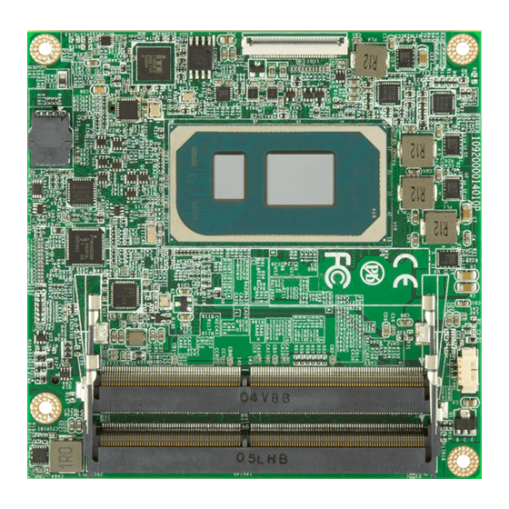
Board Overview 2.4 Connector Pin Definition Being a most commonly-used Type 6, the EmETXe-i92U0 features two board- to-board connectors on bottom side. Top Side Fan Connector So-Dimm Sockets MIPI DSI Bottom Side COM Express Connectors - 11 -... - Page 20 Board Overview FAN1: Fan connctor Connector type: Wafer 3-pin 1.25mm 85204-03X0L Description Fan out Fan Tachometer Input MIPI DSI: MIPI DSI connector (by OEM request) Connector type: Wafer 35-pin Description Pin Description 3V3-LCD MIPI_TCN0 3V3-LCD MIPI_TCP0 3V3-LCD LCD_RST NC_24 LEDK MIPI_TDN3 LEDK MIPI_TDP3...
- Page 21 Board Overview COM Express AB Connector (bottom side) PCIE_RX4- PCIE_TX4- GBE0_ACT# GBE0_MDI3- GPO2 LPC_FRAME# GBE0_MDI3+ PCIE_RX3+ PCIE_TX3+ LPC_AD0 GBE0_LINK100# PCIE_RX3- PCIE_TX3- LPC_AD1 GBE0_LINK1000# LPC_AD2 GBE0_MDI2- PCIE_RX2+ PCIE_TX2+ LPC_AD3 GBE0_MDI2+ PCIE_RX2- PCIE_TX2- LPC_DRQ0# GBE0_LINK# GPO3 GPI1 LPC_DRQ1# GBE0_MDI1- PCIE_RX1+ PCIE_TX1+ LPC_CLK GBE0_MDI1+ PCIE_RX1- PCIE_TX1-...
- Page 22 Board Overview COM Express CD Connector (bottom side) TYPE2# USB_SSTX0- USB_SSRX0- USB_SSTX0+ USB_SSRX0+ USB_SSTX1- USB_SSRX1+ USB_SSTX1+ USB_SSRX1- RSV18 USB_SSTX2- USB_SSRX2- RSV19 USB_SSTX2+ USB_SSRX2+ USB_SSRX3- USB_SSTX3- RSV20 USB_SSTX3+ USB_SSRX3+ DDI1_CTRLCLK_AUX+ DDI1_CTRLCLK_AUX- RSV10 RSV8 RSV7 RSV9 PCIE_TX6+ PCIE_RX6+ PCIE_TX6- PCIE_RX6- PCIE_TX7+ PCIE_RX7+ RSV17 PCIE_TX7- PCIE_RX7-...
-
Page 23: Chapter 3 - Installation & Maintenance
Installation & Maintenance Chapter 3 Installation & Maintenance - 15 -... -
Page 24: Installing The Cpu Module To Carrier Board
Installation & Maintenance 3.1 Installing the CPU Module to Carrier Board 1. Mount the EmETXe-i92U0 into PBE-1705 via COM Express connectors as below; that is, COM Express AB to AB and CD to CD. CD connector AB connector 2. Install the optional heat spreader or heat sink with fan to the COM module. - Page 25 Installation & Maintenance For heat sink with fan Apply thermal grease to the CPU area on the CPU module. Place the heat sink over the CPU module and fasten the six screws to secure it in place. Then connect the fan cable to the fan connector on the carrier board.
- Page 26 This page is intentionally left blank. - 18 -...
-
Page 27: Chapter 4 - Bios
BIOS Chapter 4 BIOS - 19 -... -
Page 28: Main
BIOS 4.1 Main The AMI BIOS provides a Setup utility program for specifying the system configurations and settings. The BIOS RAM of the system stores the Setup utility and configurations. When you turn on the computer, the AMI BIOS is immediately activated. - Page 29 BIOS Set the system time. Use Tab to switch between Time elements. System Time The time format is: Hour: 00 to 23 ► Minute: 00 to 59 Second: 00 to 59 Key Commands BIOS Setup Utility is mainly a key-based navigation interface. Please refer to the following key command instructions for navigation process.
-
Page 30: Advanced
BIOS 4.2 Advanced Setting Description CPU Configuration 4.2.1 CPU Configuration on page Power & Performance 4.2.2 Power & Performance on page PCH-FW Configuration 4.2.3 PCH-FW Configuration on page Trusted Computing 4.2.4 Trusted Computing on page ACPI Settings 4.2.5 ACPI Settings on page Hardware Monitor 4.2.6 Hardware Monitor... -
Page 31: Cpu Configuration
BIOS 4.2.1 CPU Configuration Setting Description Enable or disable Intel virtualization technology. When enabled, a VMM can utilize the additional Intel (VMX) Virtual- hardware capabilities provide by Vanderpool Tech- ization nology. Options: Enabled (default) or Disabled ► Number of cores to enable in each processor pack- Active Processor age. -
Page 32: Power & Performance
BIOS 4.2.2 Power & Performance Setting Description Set the performance state that the BIOS will set before Boot performance the OS handoff. Mode Options: Max Non-Turbo Performance, Max ► Power Saving and Turbo Performance (default) Enable (default)/Disable processor Trubo Mode Intel (R) Speed Step (requires Intel SpeedStep or Intel Speed Shift to be (tm) -
Page 33: Pch-Fw Configuration
BIOS 4.2.3 PCH-FW Configuration Description Setting Enable / Disable (Default) ME state. When dis- ME State abled, ME will be put into ME Temporariily Dis- abled Mode. - 25 -... -
Page 34: Trusted Computing
BIOS 4.2.4 Trusted Computing Setting Description Enable (default) or Disable BIOS support for security Security Device device. O.S. will not show Security Device. TCG EFI Support protocol and INT1A interface will not be available. Select the TPM device: Options: TPM 1.2, TPM 2.0 and Auto (default) ►... -
Page 35: Acpi Settings
BIOS 4.2.5 ACPI Settings Setting Description Enable (default) or Disable System ability to Hiber- Enable Hibernation nate (OS/S4 Sleep State). This option may be not effective with some OS. Select the highest ACPI sleep state the system will enter when the SUSPEND button is pressed. ACPI Sleep State Options: Suspend Disabled and S3 (Suspend ►... -
Page 36: Hardware Monitor
BIOS 4.2.6 Hardware Monitor Access this submenu to monitor the hardware status. - 28 -... -
Page 37: Super Io Configuration
BIOS 4.2.7 Super IO Configuration Setting Description Serial Port 1/2/3/4 & Par- See next page. allel Port Configuration Specify what state to go to when power is re-applied after a power failure. Restore AC Power Loss Options: Last State, Power On and ►... - Page 38 BIOS Serial Port 1/2/3/4 Configuration Setting Description Serial Port Enable (default) or Disable Serial Port (COM). Select an optimal setting for Super IO device. Options for Serial Port 1: ► Auto; IO=3F8h; IRQ=4 (default) ; IO=3F8h; IRQ=5, 7, 10, 11, 12 IO=2E8h;...
- Page 39 BIOS Parallel Port Configuration Setting Description Enable (default) or Disable Parallel Port (LPT/LPTE). Parallel Port Select an optimal setting for Super IO device. Options: ► Auto IO=378h; IRQ=7 (default) Change Settings IO=378h; IRQ=7, 10, 11, 12 IO=278h; IRQ=7, 10, 11, 12 IO=3BCh;...
-
Page 40: S5 Rtc Configuration
BIOS 4.2.8 S5 RTC Configuration Setting Description Enable or Disable (default) system wake on alarm event. Options available are: ► Disabled (default): Wake System Fixed Time: System will wake on the hr::min::sec from S5 specifiedc. DynamicTime: If selected, you need to set Wake up minute increase from 1 - 5. -
Page 41: Pci Subsystem Settings
BIOS 4.2.9 PCI Subsystem Settings Setting Description Value to be programmed into PCI Latency timer Register. PCI Latency Timer Default: 32 PCI Bus Clocks ► PCI-X Latency Value to be programmed into PCI Latency timer Register. Timer Default: 64 PCI Bus Clocks ►... -
Page 42: Pci Express Setting
BIOS 4.2.9.1 PCI Express Setting Setting Description Relaxed Ordering Enable(default) or Disable Relaxed Ordering. Enable or Disable(default) Extended Tag. Extended Tag No Snoop Enable(default)/Disable No Snoop. Maximum Payload This item allows users to set the Maximum Payload. Enable/Disable(default) or Auto ASPM Support. ASPM Support Extended Synch Enable or Disable(default) Extended Synch. -
Page 43: Pci Express Gen 2 Settings
BIOS 4.2.9.2 PCI Express GEN 2 Settings Setting Description PCI Express Root Control the PCI Express Root Port. Port1 Enable(default) or Disable PCI Express Active State Power Management settings. ASPM Enable or Disable(default) ASPM. UPTP: Upstream Port Transmitter Preset. Values: 7 (Default) CPU PCIe Gen3 DPTP: Downstream Port Transmitter Preset. -
Page 44: Usb Configuration
BIOS 4.2.10 USB Configuration Setting Description Sets legacy USB support. Options: Enabled (default), Disabled and Auto. ► Legacy USB AUTO option disables legacy support if no USB Support devices are connected. Disable option will keep USB devices available only for EFI applications. Enable (default) or Disable XHCI Hand-off This is a workaround for OSes without XHCI hand- XHCI Hand-off... - Page 45 BIOS Use this item to set USB mass storage device start unit Device reset time- command time-out. Options available are: 10 sec, 20 sec (default), 30 sec, 40 sec Use this item to set maximum time the device will take before it properly reports itself to the host controller.
-
Page 46: Network Stack Configuration
BIOS 4.2.11 Network Stack Configuration Setting Description Enables/disables UEFI network stack. Network Stack Disabled is the default. ► - 38 -... -
Page 47: Nvme Configuration
BIOS 4.2.12 NVMe Configuration Access this submenu to view the NVMe controller and driver information. - 39 -... -
Page 48: Chipset
BIOS 4.3 Chipset Setting Description System Agent (SA) Con- 4.3.1 System Agent (SA) Configuration figuration page PCH-IO Configuration 4.3.2 PCH-IO Configuration on page - 40 -... -
Page 49: System Agent (Sa) Configuration
BIOS 4.3.1 System Agent (SA) Configuration Setting Description VT-d Enable (default) or Disable VT-d function Enable or Disable (default) Above 4GB Above 4GB MMIO BIOS MmemoryMapped BIOS assignment. This is assignment automatically enabled when Aperture Size is set to 2048MB. Display Control Select the Video Device which will be activat- ed during POST. -
Page 50: Pch-Io Configuration
BIOS 4.3.2 PCH-IO Configuration Setting Description PCI Express Configura- 4.3.2.1 PCI Express Configuration on page tion SATA Configuration 4.3.2.2 SATA Configuration on page USB Configuration 4.3.2.3 USB Configuration on page 4.3.2.4 HD Audio Configuration on page HD Audio Configuration - 42 -... -
Page 51: Pci Express Configuration
BIOS 4.3.2.1 PCI Express Configuration Setting Description PCI Express PCI Express Root Port Settingss Root Port 5-11 - 43 -... - Page 52 BIOS 4.3.2.2 SATA Configuration Setting Description SATA Controller`(s) Enable (default) or Disable SATA Device. Determines how SATA controller(s) operate. SATA Mode Selection Options: AHCI (default) and RAID ► Port 0/1 Enable or Disable(default) SATA Port. Hot Plug Enable or Disable (default) the port as pluggable. Identify the SATA port is connected to Solid State Drive or hard Disk Drive.
- Page 53 BIOS 4.3.2.3 USB Configuration Setting Description Selectively Enable/Disable (default) the correspond- ing USB port from reporting a Device Connection to USB Port Disable the controller. Override Options: Disable Link (default) and Select Per- ► - 45 -...
- Page 54 BIOS 4.3.2.4 HD Audio Configuration Setting Description Control Detection of the HD-Audio device. Options available are: ► Disabled: HDA will be unconditionally dis- HD Audio Configura- tion abled Enabled (default): HDA will be unconditionally Enabled - 46 -...
-
Page 55: Security
BIOS 4.4 Security Setting Description To set up an administrator password: 1. Select Administrator Password. The screen then pops up an Create New Password Administrator dialog. Password 2. Enter your desired password that is no less than 3 char- acters and no more than 20 characters. 3. -
Page 56: Boot
BIOS 4.5 Boot Setting Description Select the keyboard NumLock state. Boot NumLock State Options: On (default) and Off. ► Enable or Disable (default) boot with initializa- tion of a minimal set of devices required to launch Fast Boot active boot option. Has no effect for.BBS boot options. -
Page 57: Save & Exit
BIOS 4.6 Save & Exit Setting Description Exit system setup after saving the changes. Save Changes and Enter the item and then a dialog box pops up: ► Exit Save configuration and exit? (Yes/ No) Exit system setup without saving the changes. Discard Changes and Enter the item and then a dialog box pops up: ►... - Page 58 This page is intentionally left blank. - 50 -...
-
Page 59: Appendix
Appendix Appendix - 51 -... -
Page 60: Appendix A: Watchdog Timer (Wdt) Setting
Before WDT time out, the functional normal system will reload the WDT. The WDT never time out for a normal system. The WDT will not be reloaded by an abnormal system, then WDT will time out and reset the system automatically to avoid abnormal operation. - Page 61 Appendix void WDT_Stop(void) outportb(0x66,0xBB); /* Disable Watch Dog */ void WDT_Clear(void) outportb(0x66,0xBA); /* Enable Watch Dog */ delay(2000); outportb(0x62, WDTCount); /* Number is Watch Dog Down count number */ delay(2000); outportb(0x62, 0x00); /* Minute is 1 count unit by minute */ /* Minute is 0 count unit by second */} - 53 -...
-
Page 62: Appendix B: Dio Sample Code
Appendix Appendix B: DIO Sample Code /*---------------------------------------------------------------------------*/ #include “math.h” #include “stdio.h” #include “dos.h” void GPIOMode(int iMode); void GPIOData(int iData); GPIOStatus(); int main(void) int iInput; GPIOMode(0xF); delay(10000); GPIOData(0x0A); delay(30000); iInput = GPIOStatus(); printf(“ Data : %2x \n”,iInput); GPIOData(0x05); delay(30000); iInput = GPIOStatus(); printf(“...
Need help?
Do you have a question about the EmETXe-i92U0 and is the answer not in the manual?
Questions and answers