
Subscribe to Our Youtube Channel
Related Manuals for Echo BearCat CH611DH


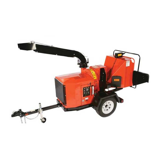
Summary of Contents for Echo BearCat CH611DH
- Page 1 6 INCH CHIPPER CH611DH – 1.1 L Diesel Kubota ® PN: 72727-00 Rev. 040918 bearcatproducts.com Companion to 72728-00 Range: 5VJAA0412JW005859 - Current...
- Page 2 Please read and understand this manual before operating your machine. If you have any questions or comments about this manual, please call us toll-free at 888.625.4520. If you have any questions or problems with your machine, please call or write your local authorized ECHO Bear Cat dealer.
- Page 3 Repair or attempted repair by anyone other than an authorized ECHO Bear Cat dealer as well as subsequent failure or damage that may occur as a result of that work will not be paid under this warranty.
-
Page 4: Table Of Contents
TABLE OF CONTENTS SAFETY ..............1 SERVICE & MAINTENANCE ......21 1.1 SAFETY ALERT SYMBOL ........1 5.1 MAINTENANCE SCHEDULE ......... 21 1.2 FIRE HAZARD INFORMATION ........ 1 5.2 ROTOR LOCK ............22 1.3 BEFORE OPERATING ..........1 5.3 RAISE/LOWER ACCESS COVER ......22 1.4 OPERATION SAFETY .......... -
Page 5: Safety
SAFETY Section The engine on your power equipment, like most outdoor 1.1 SAFETY ALERT SYMBOL power equipment, is an internal combustion engine that burns gasoline or diesel fuel (hydrocarbons). If operating your power equipment in affected areas, it must be equipped with a spark arrestor in continuous effective working order. -
Page 6: Operation Safety
SAFETY 7. Do not operate this equipment in the vicinity of 6. The rotor will continue to rotate after being disengaged. bystanders. Keep the area of operation clear of all Shut off the machine and make sure all moving parts persons, particularly small children. -
Page 7: Battery Safety
SAFETY 6. Stand to side of feed chute when feeding material 1.7 MAINTENANCE/STORAGE SAFETY and release material quickly. 7. When inspecting or servicing the feed roller, secure 1. Before inspecting, servicing, storing, or changing the feed roller in the raised position using the lock pin, an accessory, shut off the machine and make sure if applicable. -
Page 8: Safety Decals
SAFETY 1.9 SAFETY DECALS See Section 1.10 for decal locations. Familiarize yourself with all of the safety and operating decals on the machine and the associated hazards. See the engine owner’s manual or contact the engine manufacturer for engine safety instructions and decals. -
Page 9: Safety Decal Locations
SAFETY PN 32327-00 ENG. & FR. PN 32330-00 ENG. & FR. (32339-00 ESP. & PORT.) (32342-00 ESP. & PORT.) PN 32328-00 ENG. & FR. PN 32332-00 ENG. & FR. (32340-00 ESP. & PORT.) (32341-00 ESP. & PORT.) *Decals 11-14 not for CE compliant machines. 1.10 SAFETY DECAL LOCATIONS The numbers below correspond to the decals in Section 1.9. -
Page 10: Assembly
ASSEMBLY Section 2. Attach coupler mount (7) to hitch pole using two 5/8 × WARNING 4-1/2" bolts (1), washers (2) and centerlock nuts (5). Torque to 150 ft-lbs. If any bolts or nuts are dropped in the machine, be 3. Attach 2" coupler (6) to coupler mount using two 1/2 sure to remove them before starting the machine. -
Page 11: Install Rear Stabilizer
ASSEMBLY 13. Place pivot jack (16) into position on the coupler assembly mounting bracket. 14. Align jack clamp bracket (17) over the jack and secure to the coupler mounting bracket by vertically inserting an M8 × 140mm bolt (18) through the holes. Add nylock nut and tighten securely while still allowing clamp to pivot. -
Page 12: Attach License Plate Light
ASSEMBLY 1. Attach the feed chute (1) to the chipper body using 2.5 ATTACH LICENSE PLATE LIGHT nine 3/8 × 1-1/4" carriage bolts (2) and nylock nuts. For the two upper bolt locations, insert the bolts from 1. Attach the license plate light to the chute support, inside the feed roller housing. -
Page 13: Attach Digital Display Controller Mount Assembly
ASSEMBLY 2.6 ATTACH DIGITAL DISPLAY CONTROLLER MOUNT ASSEMBLY 1. Remove the bolts (1) and nuts (2) attaching the digital display controller mount assembly (3) to the inside of the chute. 2. Attach mount assembly to the outside of the chute as shown. -
Page 14: Add Oil To Engine
ASSEMBLY 7. Attach the discharge deflector (7) to the discharge tube. 2.10 ADD COOLANT Connect the deflector with two 5/16 × 1-1/4" carriage bolts (8) through the lower hole in the discharge tube. Check the level of coolant before you start the diesel Run these bolts through the inside of the tube, 3/8"... -
Page 15: Fill The Fuel Tank
ASSEMBLY 2.12 FILL THE FUEL TANK Use only those types of fuels that are recommended in WARNING your engine owner’s manual. To add fuel: Gasoline and diesel fuels are highly 1. Stop engine and wait for all parts to stop moving. flammable their vapors... -
Page 16: Features & Controls
FEATURES & CONTROLS Section Understanding how your machine works will help you achieve the best results when using your chipper. The following descriptions define the features and controls of your machine. REFER TO ENGINE OWNER’S MANUAL FOR FURTHER ENGINE OPERATING INSTRUCTIONS. CH611DHXE MODEL 6 INCH CHIPPER... - Page 17 FEATURES & CONTROLS 1. CHUTE EXTENSION TRAY 12. MANUAL CONTAINER The feed chute has an extension tray that folds down. Conveniently holds your manuals. Raise the extension tray to an upright position and 13. REAR STABILIZER secure with latch before towing the machine. Prevents the chipper from tipping when disconnected 2.
-
Page 18: Operation
OPERATION Section As with any other piece of outdoor equipment, getting the 5. Turn key to the right or “On” position. Press glow plug feel for how your machine operates and getting to know button for 5-10 seconds (not necessary for warm the best techniques for particular jobs are important to engine). - Page 19 OPERATION 3. If the chipper engine stalls while engaging the belt, move engagement handle back to the START position, restart engine, SLIGHTLY increase throttle and attempt engagement again. 4. Once the belt is engaged, continue to SLOWLY turn the throttle knob counterclockwise to increase throttle to 100% or full throttle.
-
Page 20: Chipper Operation Guidelines
OPERATION 4.3 CHIPPER OPERATION GUIDELINES 7. Limbs fed in to the chipper chute must be 6" WARNING (15.2 cm) in diameter or less. Trim side branches that cannot be bent enough to feed into the chipper Read and follow all safety instructions in this manual. chute. -
Page 21: Slowing And Stopping The Chipper Rotor And Engine
OPERATION 4.6 CHIPPER FEED CONTROLLER 4.4 SLOWING AND STOPPING THE CHIPPER ROTOR AND ENGINE This machine is equipped with a Digital Display Controller (DDC). The DDC monitors the chipper rotor RPM and NEVER disengage the belt as part of the stopping or regulates the feed roller. -
Page 22: Using The Digital Display Controller
The model number shown should match here. the model of the chipper. If it does not contact ECHO Bear NOTE Cat Service at 888-625-4520 for help. A scannable QR code is located in the lower left corner. It Consult the Controller Manual (P/N 71983-00) for will lead you to the ECHO Bear Cat website where owner’s... - Page 23 OPERATION In the upper left hand corner of the screen is a reminder The Knee Bar Reset button resets the controller so that the feed roller speed can be adjusted. The adjustment Forward and Reverse can be re-engaged after the Knee Bar safety system has been activated.
-
Page 24: Towing
OPERATION Engine – Hours are based on “Key On” time. The service interval is dependent on the model selected. (Does not ● apply to PTO driven models.) Hydraulic System – Hours are based on “Key On” time. First service interval is at 50 hours; subsequent service ●... -
Page 25: Service & Maintenance
SERVICE & MAINTENANCE Section 5.1 MAINTENANCE SCHEDULE The items listed in this service and maintenance schedule are to be checked, and if necessary, corrective action taken. This schedule is designed for units operating under normal conditions. If the unit is operating in adverse or severe conditions, it may be necessary for the items to be checked and serviced more frequently. -
Page 26: Rotor Lock
SERVICE & MAINTENANCE WARNING BEFORE INSPECTING OR SERVICING ANY PART OF THIS MACHINE, SHUT OFF POWER SOURCE, DISENGAGE THE HYDRAULICS, OPEN SHIELD AND MAKE SURE ALL MOVING PARTS HAVE COME TO A COMPLETE STOP. 5.2 ROTOR LOCK 5.4 CHIPPER BLADES MAINTENANCE The chipper blades will eventually become dull, making WARNING chipping difficult and adding extra strain on the machine. -
Page 27: Removing The Blades
SERVICE & MAINTENANCE WARNING BEFORE INSPECTING OR SERVICING ANY PART OF THIS MACHINE, SHUT OFF POWER SOURCE, DISENGAGE THE HYDRAULICS, OPEN SHIELD AND MAKE SURE ALL MOVING PARTS HAVE COME TO A COMPLETE STOP. 5.5 REMOVING THE BLADES WARNING Chipping blades are sharp! Use caution when working on machine to avoid injury. -
Page 28: Setting Chipper Blade Clearance
SERVICE & MAINTENANCE WARNING BEFORE INSPECTING OR SERVICING ANY PART OF THIS MACHINE, SHUT OFF POWER SOURCE, DISENGAGE THE HYDRAULICS, OPEN SHIELD AND MAKE SURE ALL MOVING PARTS HAVE COME TO A COMPLETE STOP. 5.8 SETTING CHIPPER BLADE CLEARANCE The chipping blades should clear the chipper block located directly under the chipper chute by 1/16" to 1/8". To adjust the blade clearance, proceed as follows: 1. -
Page 29: Drive Belts
SERVICE & MAINTENANCE WARNING BEFORE INSPECTING OR SERVICING ANY PART OF THIS MACHINE, SHUT OFF POWER SOURCE, DISENGAGE THE HYDRAULICS, OPEN SHIELD AND MAKE SURE ALL MOVING PARTS HAVE COME TO A COMPLETE STOP. Feeding too large or too much material at once may plug 5.11 DRIVE BELTS the chipper. -
Page 30: Rotor Bearings
SERVICE & MAINTENANCE WARNING BEFORE INSPECTING OR SERVICING ANY PART OF THIS MACHINE, SHUT OFF POWER SOURCE, DISENGAGE THE HYDRAULICS, OPEN SHIELD AND MAKE SURE ALL MOVING PARTS HAVE COME TO A COMPLETE STOP. 5.11.2 HYDRAULIC DRIVE BELT 5.12 ROTOR BEARINGS The condition of the hydraulic drive belt should be checked annually, or after every 25 hours of operation. -
Page 31: Hydraulic Feed Maintenance
SERVICE & MAINTENANCE WARNING BEFORE INSPECTING OR SERVICING ANY PART OF THIS MACHINE, SHUT OFF POWER SOURCE, DISENGAGE THE HYDRAULICS, OPEN SHIELD AND MAKE SURE ALL MOVING PARTS HAVE COME TO A COMPLETE STOP. 5.13 HYDRAULIC FEED MAINTENANCE 5.14 CHANGE HYDRAULIC FLUID FILTER Hydraulic fluid drives the feed roller. -
Page 32: Lubrication
SERVICE & MAINTENANCE WARNING BEFORE INSPECTING OR SERVICING ANY PART OF THIS MACHINE, SHUT OFF POWER SOURCE, DISENGAGE THE HYDRAULICS, OPEN SHIELD AND MAKE SURE ALL MOVING PARTS HAVE COME TO A COMPLETE STOP. 5.18 LUBRICATION Lubricate the machine periodically with a lithium-based WARNING grease. -
Page 33: Troubleshooting
TROUBLESHOOTING Section 6.1 FLASH CODES FOR THE DIGITAL DISPLAY CONTROLLER FREQUENCY CAUSE ACTION TO TAKE GREEN Chipper has reached required RPM and forward feed Solid Machine ready for chipping is available 1/2 second on, Chipper has not reached chipping RPM upon initial Slowly increase RPM 1/2 second off startup... -
Page 34: Troubleshooting Guide
6.2 TROUBLESHOOTING GUIDE Before performing any of the corrections in this troubleshooting chart, refer to the appropriate information contained in this manual for the correct safety precautions and operating or maintenance procedures. Contact your dealer or ECHO Bear Cat for service problems with the machine. - Page 35 TROUBLESHOOTING PROBLEM POSSIBLE CAUSES REMEDY Dull chipper blades Flip, sharpen, or replace Hard to feed chipper, Use branch or similar object to clear Obstructed discharge requires excessive discharge tube power to chip Set blade/anvil clearance to recommended Improper blade clearance distance Dull chipper blades Flip, sharpen, or replace...
-
Page 36: Specifications
SPECIFICATIONS Section DESCRIPTION ENGLISH METRIC Engine Kubota 1.1 L diesel, model 1105B-1 ® Fuel Capacity 9 gallons 34.1 liters Maximum Chipper Capacity 6" diameter 15.2 cm diameter Chipper Blades 4 reversible (5" × 4" × 0.5") 4 reversible (12.7 cm × 10.2 cm × 1.3 cm) 4-edge adjustable 4-edge adjustable Chipping Anvil... -
Page 37: Bolt Torque
SPECIFICATIONS 7.1 BOLT TORQUE The tables below are for reference purposes only and their use by anyone is entirely voluntary, unless otherwise noted. Reliance on their content for any purpose is at the sole risk of that person and any loss or damage resulting from the use of this information is the responsibility of that person. -
Page 38: Temperature Operating Window
SPECIFICATIONS 7.2 TEMPERATURE OPERATING WINDOW For the nearest Mobil lubricant supplier or technical information, including lubricant information for severe arctic operating conditions, call 800-662-4525. 6 INCH CHIPPER... -
Page 39: Options
OPTIONS Section PART NUMBER DESCRIPTION 14519-00 COUPLER, 2-5/16 20,000 LB. 14900-00 HITCH, PINTLE RING 20,000 LB. 33900-00 DSE, KEY 71930-00 KIT, 6" LOW PROFILE DISCHARGE 75291-00 KIT, SPARE TIRE 76196-00 KIT, 6 IN SAFETY BAR 76293-00 KIT, CHIPPER BLADE (1/2 INCH) 76722-00 KIT, BATTERY DISCONNECT 2-5/16"... - Page 40 ECHO Bear Cat ® bearcatproducts.com 237 NW 12th Street, West Fargo, ND 58078-0849 Phone: 701.282.5520 • Toll Free: 888.625.4520 • Fax: 701.282.9522 E-mail: service@bearcatproducts.com • sales@bearcatproducts.com...
Need help?
Do you have a question about the BearCat CH611DH and is the answer not in the manual?
Questions and answers