Table of Contents
Advertisement
PRODUCT DATA SHEET
Dry-Break Diesel Refuelling Nozzles
Banlaw ReFuelling™
Thank you for purchasing this high quality Banlaw product. Please read through and
understand the information in this Product Data Sheet (PDS) BEFORE installation or operation
of the product to avoid accidental personal injury or property damage.
1 PRODUCT DESCRIPTION
Banlaw Dry-Break Diesel Refuelling Nozzles are fluid (e.g. diesel fuel) dispensing couplings which
incorporate both calibrated (automatic) pressure shut-off, and "dry break" functions.
Banlaw introduced their first dry-break diesel refuelling nozzles into the market in the 1980's in
response to a requirement for a more ergonomic and robust "industry standard" nozzle rated for higher
diesel flowrates.
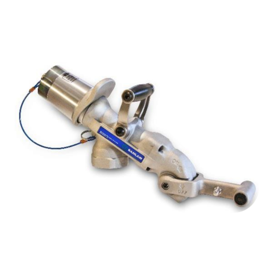
1000 Series
800 Series
Figure 1 - Examples of Banlaw Nozzles
Figure 1 shows examples of current Banlaw 800 and 1000 series Nozzles. The "800" refers to the
maximum rated diesel flowrate of 800LPM (211GPM) of the 800 series, and likewise the "1000" refers
to the maximum rated diesel flowrate of 1000LPM (264GPM) of the 1000 series.
Banlaw Nozzles are available in a variety of models (variants) within each series, including the Banlaw
FuelTrack™ Nozzles incorporating the Banlaw proprietary automatic (vehicle) identification – i.e. "auto
#
ID" – feature. Banlaw Nozzles also incorporate other features including the patented
means of
#
adjusting the automatic shut-off setting
.
(
US 6,622,760)
The 800 series "Mining" Nozzles are compatible with the industry standard refuelling "receivers",
commonly used as the means of refuelling plant equipment and smaller bulk diesel storage tanks in the
mining and construction industries. Other 800 series models – e.g. "Rail" – and Banlaw 1000 series
Nozzles are only compatible with the matching Banlaw receiver.
This document specifically covers the principal specifications, installation, commissioning, operation,
maintenance and servicing requirements and guidelines of Banlaw 2" (DN50) Diesel Refuelling and Fluid
Transfer Nozzles. End-users requiring additional information should refer to the Banlaw website,
contact Banlaw or your nearest authorised Banlaw distributor. Similarly, persons wanting information
other Banlaw refuelling products and Nozzle accessories should also refer to the website or same
contacts.
Doc ID: PRH-REF-70
Version: 7.0
Page 1 of 32
Please ensure you have the latest version of this document.
Advertisement
Table of Contents


Need help?
Do you have a question about the 800 Series and is the answer not in the manual?
Questions and answers