
Subscribe to Our Youtube Channel
Related Manuals for FRC PRO-S 1


Summary of Contents for FRC PRO-S 1
- Page 1 PRO-S Rev1104 PRESSURE GOVERNOR FIRE RESEARCH CORPORATION http://www.fireresearch.com 26 Southern Blvd., Nesconset, NY11767 TEL ( 631 ) 724-8888 FAX ( 631 ) 360-9727 TOLL FREE 1-800-645-0074...
-
Page 2: Table Of Contents
High Idle ......................23 Pressure Transducer .................... 24 Common OME Connectors ................25 Cummins PRO-S 1 Cables .................. 26 Cummins Harness Connections ................27 Detroit Diesel (Series 50 and 60) PRO-S 2 Cables..........30 Detroit Diesel (Series 50 and 60) Harness Connections ........31 Non-Electronic Engine PRO-S 3 Cables ............. -
Page 3: List Of Tables
Figure 8. Pressure Transducer Wiring..............24 Figure 9. Common OEM Connectors ..............25 Figure 10. Cummins PRO-S 1 Wiring ..............26 Figure 11. Detroit Diesel (Series 50 and 60) PRO-S 2 Wiring ......... 30 Figure 12. Non-Electronic PRO-S 3 Wiring ............32 Figure 13. -
Page 4: Introduction
PRO-S Rev1104 INTRODUCTION Overview The Fire Research PRO-S pressure governor uses state of the art programmable microprocessor technology. It will maintain a steady pump discharge pressure by controlling the engine speed or maintain a selected engine RPM. The PRO-S will operate in one of two modes, pressure or RPM. -
Page 5: Specifications
All models provide the same functions, push button controls, and digital readout for the management of pump discharge pressure. (Refer to Table 1 for detailed specifications.) Table 1. PRO-S Specifications PRO-S 1 PRO-S 2 PRO-S 3 PRO-S 4... -
Page 6: Table 2. Pressure Transducer Output Voltage
PRO-S Rev1104 Pressure Transducer Model Number: PRO31PT2 Pressure Range: 0 - 300 PSI Proof Pressure: 800 PSI Excitation Voltage: 5 VDC Output Voltage: 0.5 - 4.75 VDC (See Table 2) Table 2. Pressure Transducer Output Voltage PRESSURE VOLTAGE (PSI) (VDC) 1.917 2.625 3.33... -
Page 7: General Description
PRO-S Rev1104 GENERAL DESCRIPTION The PRO-S pressure governors are compatible with the following engines: PRO-S 1 Cummins ISB, ISC, ISM, and ISL PRO-S 2 Detroit Diesel (Series 50 and 60) PRO-S 3 Non-Electronic diesel and gasoline PRO-S 4 Navistar and Detroit Diesel (Series 40) -
Page 8: Controls And Indicators
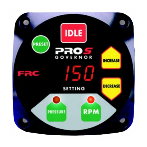
PRO-S Rev1104 Controls and Indicators All controls and indicators are located on the front of the control module. It contains the push button electronic controls, LED indicators, and a digital display. (Refer to Figure 1.) PRESET Button The green PRESET button sets the pump pressure or engine RPM to a preprogrammed value. -
Page 9: Figure 1. Controls And Indicators
PRO-S Rev1104 PRESET IDLE SETTING Button Button Display INCREASE Button DECREASE Button PRESSURE PRESSURE Button Button Figure 1. Controls and Indicators... -
Page 10: Installation
PRO-S Rev1104 INSTALLATION Install Control Module Note: The control module can be mounted anywhere on the pump panel. It should be mounted close to the engine warning indicators. 1. Measure and mark mounting location for control module panel cutout and mounting screw holes. -
Page 11: Install Pressure Transducer
PRO-S Rev1104 Install Pressure Transducer The discharge pressure transducer is mounted on the discharge manifold of the pump. A T-fitting can be used to share the master pressure gauge outlet on the discharge manifold. If there is a check valve in the discharge side of the pump, mount the transducer before the check valve. -
Page 12: Install Throttle Servomotor (Non-Electronic Engine Only)
PRO-S Rev1104 Install Throttle Servomotor (Non-Electronic Engine Only) The throttle servomotor (FRC part number PRO-34M.) is used for engines that do not have an electronic engine control system. The throttle servomotor has a universal mounting flange with six mounting holes. -
Page 13: Figure 5. Throttle Servo Motor
PRO-S Rev1104 Installation 1. Place the throttle servomotor in position and secure. Note: The total motion of the linear actuator rod is approximately 1.85 inches. The motion of the fuel control arm must be more than 1.85 inches to prevent damage to the arm. It is recommended that the fuel control arm have a two inch stroke at the point the cable attaches. -
Page 14: Install Optional High Idle
PRO-S Rev1104 Install Optional High Idle The High Idle Kit (FRC part number PRO-38H) provides the necessary components needed to install this option including a DPDT switch, 2500 ohm potentiometer, an indicator light, two diodes, and a cable. The high idle cap may be installed on the end of the control module high idle 3-pin Deutsch connector. -
Page 15: Operation
PRO-S Rev1104 OPERATION On power up the PRO-S will be in the pressure mode of operation. The SETTING display will show IdLE. If there is a problem, the SETTING display will show an error code. Refer to the Diagnostics section for error code descriptions. The minimum pump discharge pressure must be greater than 15 PSI for the PRO-S governor to take control of engine speed. -
Page 16: Pressure Mode Operation
PRO-S Rev1104 Pressure Mode Operation In the pressure mode of operation the PRESSURE LED will be on. The PRO-S will maintain a constant discharge pressure. It will adjust the engine RPM automatically to compensate for variations in pressure. Note: When changing from RPM mode to pressure mode the pressure setting will be the pressure that the pump was operating at in RPM mode. -
Page 17: Rpm Mode Operation
PRO-S Rev1104 RPM Mode Operation In the RPM mode of operation the RPM LED will be on. The PRO-S will maintain a constant engine RPM. The pump discharge pressure can vary but, as a safety feature, the PRO-S limits the increase in pressure to 30 PSI. As the discharge pressure approaches this limit the PRO-S will automatically lower the RPM to prevent a high pressure surge. -
Page 18: System Options
PRO-S Rev1104 System Options High Idle Note: If the optional remote high idle kit is not being installed, ensure that the high idle cap (supplied) is installed on the end of the control module high idle cable. The RPM that the engine will run at when the high idle circuit is engaged is set by adjusting the 2500 ohm potentiometer. -
Page 19: Calibration
PRO-S Rev1104 CALIBRATION RPM Calibration (PRO-S 3, 6, and 8) The following models of the PRO-S require the RPM control to be calibrated: PRO-S 3 Non-electronic diesel and gasoline engines PRO-S 6 Ford engines PRO-S 8 Scania engines Initial conditions To perform the following calibration procedure a reference tachometer is needed to verify the correct engine RPM, the engine must be at idle RPM, and the SETTING display on the PRO-S must show IDLE. -
Page 20: High Idle Option Calibration
PRO-S Rev1104 High Idle Option Calibration The RPM that the engine will run at when the high idle circuit is engaged is set by adjusting the 2500 ohm potentiometer. 1. Loosen the lock nut on the potentiometer. 2. Place the high idle switch to ON. 3. -
Page 21: Diagnostics
PRO-S Rev1104 DIAGNOSTICS The information listed in Table 3 is to aid in troubleshooting a problem. The diagnostic code will be shown in the SETTING display on the control module. Table 3. Diagnostic Codes Code Problem Probable Cause >No voltage at the interlock input >Datalink cable not connected / No communication on incorrectly wired... -
Page 22: Wiring
PRO-S Rev1104 WIRING The following figures include the schematics, wiring diagrams, block diagrams, and cables for the PRO-S series governors. Note: If optional 24 VDC unit is installed references to +12 VDC will be +24 VDC. Power From Control Module Power Supply 3-Pin Deutsch Connector Power Supply Cable... -
Page 23: High Idle
2500 Ohm Potentiometer High Idle ON/OFF Switch From Pump Engaged 12VDC Pump Engaged Indicator Light Diodes (IN4002 or equivalent) To Control Module White FRC kit part number Interlock Wire PRO-38H. (Located in power cable.) Figure 7. Optional High Idle Schematic... -
Page 24: Pressure Transducer
PRO-S Rev1104 Pressure Transducer From Control Module Pressure Sensor 4-Pin Deutsch Connector Pressure Transducer Cable 4-Pin Deutsch Connector Pin/Wire Description 1/Red Supply Voltage 2/Black Ground 3/White Signal Output 4/Yellow Cable Shield Pressure Transducer Cable Pressure Transducer Cable 3-Pin Sensor Connector Pin/Wire Description A/Black... -
Page 25: Common Ome Connectors
PRO-S Rev1104 Common OME Connectors Commonly found under the driver side dashboard. Typical 6-pin Deutsch diagnostic connector. Pin A J1587 Datalink Positive Pin B J1587 Datalink Negative FRONT VIEW Typical 9-pin Deutsch diagnostic connector. Pin F J1587 Datalink Positive Pin G J1587 Datalink Negative FRONT VIEW Figure 9. -
Page 26: Cummins Pro-S 1 Cables
Datalink + (See Sheet 2) B/Black Datalink – Pressure Engine Control Cable Transducer Connector (Refer to Figure 8) Pin/Wire Description A/Black Signal Return B/White Signal to ECM C/Red 5 VDC Reference Figure 10. Cummins PRO-S 1 Wiring (Sheet 1 of 3) -
Page 27: Cummins Harness Connections
ECM 50-Pin interlock circuit is engaged. ground when the J2 Connector pump interlock This assumes that the ECM is set circuit is engaged. with Automotive governor as the default mode. Figure 10. Cummins PRO-S 1 Wiring (Sheet 2 of 3) - Page 28 ECM 50-Pin ground when the interlock circuit is engaged. J2 Connector This assumes that the ECM is set pump interlock with Automotive governor as the circuit is engaged. default mode. Figure 10. Cummins PRO-S 1 Wiring (Sheet 3 of 3)
- Page 29 PRO-S Rev1104 This page intentionally left blank.
-
Page 30: Detroit Diesel (Series 50 And 60) Pro-S 2 Cables
PRO-S Rev1104 Detroit Diesel (Series 50 and 60) PRO-S 2 Cables Connector Key A 4-Pin Deutsch B 3-Pin Deutsch C 3-Pin Packard GOVERNOR D 2-Pin Packard E 3-Pin Sensor Power RPM Sig. Supply / J1587 Engine Control High Pressure Idle Sensor Power Supply High Idle Cap... -
Page 31: Detroit Diesel (Series 50 And 60) Harness Connections
PRO-S Rev1104 Detroit Diesel (Series 50 and 60) Harness Connections Interface Information Connect the Engine Control extention cable to the Variable Speed Governor input on the engine ECM. There may be a 3-pin Packard connector (Variable Speed Governor Harness Connector installed by the chassis manufacturer) located behind the pump panel to plug into for the ECM connections. -
Page 32: Non-Electronic Engine Pro-S 3 Cables
PRO-S Rev1104 Non-Electronic Engine PRO-S 3 Cables Connector Key A 4-Pin Deutsch B 3-Pin Deutsch C 2-Pin Deutsch GOVERNOR D 2-Pin Packard E 3-Pin Sensor Power RPM Sig. Supply / J1587 Engine Control High Pressure Idle Sensor Alternator Power Supply High Idle Cap (See Sheet 2) (Refer to Figure 6) -
Page 33: Non-Electronic Harness Connections
PRO-S Rev1104 Non-Electronic Harness Connections Interface Information Connect the red alternator cable wire to the small positive (+) terminal on the alternator. (Some names used for this terminal: Alternator Tap, Stator Tap, A/C Tap, Tachometer Signal Connection, Tach Output, Tach Terminal.) Do not connect the red wire to the large battery (BAT) terminal. -
Page 34: Navistar And Detroit Diesel (Series 40) Pro-S 4 Cables
PRO-S Rev1104 Navistar and Detroit Diesel (Series 40) PRO-S 4 Cables Connector Key A 4-Pin Deutsch B 3-Pin Deutsch C 3-Pin Packard GOVERNOR D 2-Pin Packard E 3-Pin Sensor Power RPM Sig. Supply / J1587 Engine Control High Pressure Idle Sensor Power Supply High Idle Cap... -
Page 35: Navistar And Detroit Diesel (Series 40) Harness Connections
PRO-S Rev1104 Navistar and Detroit Diesel (Series 40) Harness Connections Interface Information The ECM must be programmed for a remote throttle input. Set PTO REMOTE PEDAL to 1. (This will enable the remote throttle input.) The VARIABLE PTO ENABLE input has to be at 12 VDC to activate the remote throttle. -
Page 36: Caterpillar Pro-S 5 Cables
PRO-S Rev1104 Caterpillar PRO-S 5 Cables Connector Key A 4-Pin Deutsch B 3-Pin Deutsch C 2-Pin Deutsch GOVERNOR D 2-Pin Packard E 3-Pin Sensor Power RPM Sig. Supply / J1587 Engine Control High Pressure Idle Sensor Power Supply High Idle Cap J1587 Datalink (Refer to Figure 6) (Refer to Figure 7) -
Page 37: Caterpillar Harness Connections
PRO-S Rev1104 Caterpillar Harness Connections Interface Information The ECM Remote Throttle Option has to be enabled. Refer to an authorized dealer to program this option. 3116B, 3126B, 3176B, 3406E, C7, C10, C12 Engine Interface Engines with 70-pin OEM connector. J1587 Datalink Black Wire J1587 Negative (–) - Page 38 PRO-S Rev1104 3176B, 3406E, C10, C12 Engine Interface Engines with 40-pin OEM connector. J1587 Datalink Black Wire J1587 Negative (–) Datalink (See J1587 Datalink Sheet 1) Red Wire Positive (+) Multi-Function Sensor Black Wire L901-GY Common Engine Control Multi-Function Input #3 White Wire (See Sheet 1) K982-YL...
- Page 39 PRO-S Rev1104 Some Older Engine Interface Engines with 40-pin OEM connector. If the remote throttle option is not available in the ECM program, a relay needs to be installed to provide this capability. Wire the relay into the cab foot throttle harness, connect the PRO-S Engine Control cable, and supply 12 volts to the coil form the pump interlock circuit.
-
Page 40: Ford Pro-S 6 Cables
PRO-S Rev1104 Ford PRO-S 6 Cables Connector Key A 4-Pin Deutsch B 3-Pin Deutsch C 2-Pin Deutsch GOVERNOR D 3-Pin Packard E 3-Pin Sensor Power RPM Sig. Supply / J1587 Engine Control High Pressure Idle Sensor Powertrain Control Power Supply (See Sheet 2 or 3) (Refer to Figure 6) RPM Signal Connector... -
Page 41: Ford Harness Connections
PRO-S Rev1104 Ford Harness Connections Interface Information 7.3L Power Stroke Engine The PRO-S Engine Control cable needs to be wired in series with the cab foot throttle. Use a voltmeter to determine which pins are Idle Validation and Engine Control Signal. - Page 42 PRO-S Rev1104 6.0L Diesel Engine An adapter and cable assembly is needed to interface the PRO-S 6B with the 6.0L engine. Two 6 pin connectors are provided and need to be spliced into the harness between the cab foot throttle and the ECM. Do not mount the adapter assembly in the engine compartment.
-
Page 43: Ford Adapter And Cable Detail (6.0 L Engines)
PRO-S Rev1104 Ford Adapter and Cable Detail (6.0 L Engines) Note: Do not mount the adapter assembly in the engine compartment. 6.0L Adapter Assembly Connector Pin/Wire Description A/Black Ground B/White +12 V Interlock C/Red Signal To Engine ECM 3 Pin Packard Plug Note: An adapter and cable assembly... -
Page 44: Ford Torque Lock-Up Module (6.0 L Engines)
(See Sheet 3) Green wire will go low when the engine RPM goes above the program third gear lock-up setting. (Factory set to 1200 RPM.) Green Wire Wire +12 VDC FRC Torque Lock-up Module Black Wire White Blue Wire Wire... - Page 45 PRO-S Rev1104 This page intentionally left blank.
-
Page 46: Mack Pro-S 7 Cables
PRO-S Rev1104 Mack PRO-S 7 Cables Connector Key A 4-Pin Deutsch B 3-Pin Deutsch C 3-Pin Packard GOVERNOR D 2-Pin Packard E 3-Pin Sensor Power ´ ` ¸ ` ` ˜ - ´ Supply `˜`˚``` Engine Control High Pressure Idle Sensor Power Supply High Idle Cap... -
Page 47: Mack Harness Connections
PRO-S Rev1104 Mack Harness Connections Interface Information The PRO-S Engine Control cable needs to be wired in series with the cab foot throttle. Use a voltmeter to determine which pin is Engine Control Signal. Engine Control Signal will be 0.7 volts at idle and rise to approximately 3.8 volts as the foot pedal is pressed. -
Page 48: Scania Pro-S 8 Cables
PRO-S Rev1104 Scania PRO-S 8 Cables Connector Key A 4-Pin Deutsch B 3-Pin Deutsch C 2-Pin Deutsch GOVERNOR D 3-Pin Packard E 3-Pin Sensor Power RPM Sig. Supply / J1587 Engine Control High Pressure Idle Sensor Alternator Power Supply High Idle Cap (See Sheet 2) (Refer to Figure 6) (Refer to Figure 7) -
Page 49: Scania Harness Connections
PRO-S Rev1104 Scania Harness Connections Interface Information Connect the alternator cable red wire to the small positive (+) terminal on the alternator and the black wire to chassis ground. Do not connect the wires to the large battery terminals. Pin A - 5V Reference Pin B - Signal Return Pin C - Engine Control Engine... -
Page 50: Mercedes Pro-S 10 Cables
PRO-S Rev1104 Mercedes PRO-S 10 Cables Connector Key A 4-Pin Deutsch B 3-Pin Deutsch C 3-Pin Packard GOVERNOR D 2-Pin Packard E 3-Pin Sensor Power RPM Sig. Supply / J1587 Engine Control High Pressure Idle Sensor Power Supply High Idle Cap J1587 Datalink (Refer to Figure 6) (Refer to Figure 7) -
Page 51: Mercedes Harness Connections
PRO-S Rev1104 Mercedes Harness Connections Interface Information J1587 J1587 (–) Black Wire Datalink (See J1587 (+) Sheet 1) Red Wire Sensor Ground (Throttle Pedal & Remote) 21-Pin Connector Engine Black Wire Remote PTO Power Supply Control Red Wire Remote Throttle Signal Analog (See Sheet 1) White Wire Throttle Select... -
Page 52: Flyback Diode Wiring
(seloniod coil, relay coil, electric motor winding, etc.). It is recommended that a flyback diode be installed on inductive devices that share a common power source/ ground with a FRC governor. Typical circuit showing a flyback diode installed across an inductive load.
Need help?
Do you have a question about the PRO-S 1 and is the answer not in the manual?
Questions and answers