Table of Contents
Advertisement
Quick Links
Advertisement
Table of Contents

Subscribe to Our Youtube Channel
Related Manuals for FRC PumpBoss PBA100


Summary of Contents for FRC PumpBoss PBA100
- Page 1 PBA100 Rev0305PreLim PRESSURE GOVERNOR AND ENGINE STATUS DISPLAY PRELIMINARY DOCUMENT FOR REFERENCE/REVIEW ONLY PBA100 FIRE RESEARCH CORPORATION www.fireresearch.com 26 Southern Blvd., Nesconset, NY11767 TEL ( 631 ) 724-8888 FAX ( 631 ) 360-9727 TOLL FREE 1-800-645-0074...
-
Page 2: Table Of Contents
PBA100 Rev0305PreLim CONTENTS Table of Contents CONTENTS ....................... 2 INTRODUCTION ...................... 4 Overview ........................ 4 Features........................4 Specifications......................5 GENERAL DESCRIPTION..................6 Controls and Indicators ..................8 INSTALLATION ...................... 10 Install Control Module ..................10 Install Pressure Sensor ..................12 Install Sensors ...................... - Page 3 PBA100 Rev0305PreLim List of Tables Table 1. Pressure Sensor Output Voltage ..............5 Table 2. Error Codes ....................15 Table 3. Fault Warning Codes.................. 15 List of Figures Figure 1. Controls and Indicators ................9 Figure 2. Control Module Mounting Dimensions ............ 11 Figure 3.
-
Page 4: Introduction
PBA100 Rev0305PreLim INTRODUCTION Overview The Fire Research PumpBoss pressure governor uses state of the art programmable microprocessor technology and operates in one of two modes, pressure or RPM. It will maintain a steady pump discharge pressure within system capabilities by controlling the engine speed. -
Page 5: Specifications
PBA100 Rev0305PreLim Specifications The PumpBoss is available in various models. Each model is programmed to interface with specific engines. All models provide the same functions, controls, and digital readouts for the management of pump discharge pressure. Display Module Supply Power: 9 - 30 VDC Supply Current: 0.5 Amps... -
Page 6: General Description
PBA100 Rev0305PreLim GENERAL DESCRIPTION The PumpBoss pressure governors are compatible with the following engines: PBA101 Cummins IS Series PBA102 Detroit Diesel PBA104 Navistar PBA105 Caterpillar PBA106* Ford PBA107 Mack PBA108 Scania PBA109* PBA110 Mercedes * Note: An adapter and cable assembly replaces the basic 8-pin cable when connecting the to a Ford 6.0 or GMC engine. - Page 7 PBA100 Rev0305PreLim Contol Panel The control panel is waterproof and takes up 4 5/8 by 6 3/4 inches of panel space. All controls and indicators are located on the front of the control panel. (Refer to Controls and Indicators.) Pressure Sensor The pressure sensor is mounted on the pump discharge manifold.
-
Page 8: Controls And Indicators
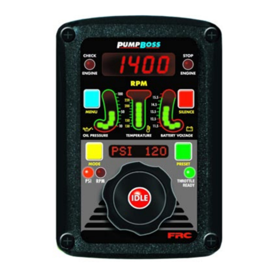
PBA100 Rev0305PreLim Controls and Indicators All controls and indicators are located on the front of the control module. (Refer to Figure 1.) See Operation and Programming Sections for more information. OIL PRESSURE LED Display Shows engine oil pressure. The LEDs will be green when the pressure is within normal limits and red when it is not. -
Page 9: Figure 1. Controls And Indicators
PBA100 Rev0305PreLim Control Knob When rotated changes the pressuer or RPM setting. The setting will increase or decrease proportionally to the speed and direction the control knob is rotated. RPM LED The LED is on to indicate operation in the RPM mode. PSI LED The LED is on to indicate operation in the PSI mode. -
Page 10: Installation
PBA100 Rev0305PreLim INSTALLATION Install Control Module 1. Measure and mark mounting location for control module panel cutout and mounting screw holes. Make sure there is clearance behind the panel for the module and cables before cutting holes. Refer to Figure 2 for layout and dimensions. -
Page 11: Figure 2. Control Module Mounting Dimensions
PBA100 Rev0305PreLim 4" 3 7/16" Panel 5 3/4" Cutout Maximum Radius 1/2" Mounting holes are clearance or tapped 5 11/16" for 10-32 screws. 1 3/4" 4 5/8" 6 3/4" Figure 2. Control Module Mounting Dimensions... -
Page 12: Install Pressure Sensor
PBA100 Rev0305PreLim Install Pressure Sensor The discharge pressure sensor is mounted on the discharge manifold of the pump. If there is a check valve in the discharge side of the pump, mount the discharge sensor before the check valve. T-fittings can be used to mount the pressure sensors. Note: Install the pressure sensor upright so water in the end of the sensor is able to drain back into the pipe. -
Page 13: Install Sensors
Pin 6 on the 12-pin connector at the rear of the control module is provided to connect an optional buzzer. Connect the ground side of the buzzer to pin 6. Maximum current through pin 6 is 300 mA. The buzzer ordered from FRC requires a 1-1/8 inch diameter mounting hole. (Refer to the Wiring section.) -
Page 14: Operation
PBA100 Rev0305PreLim OPERATION On power-up the PumpBoss will be in normal operating mode. The RPM display will show engine RPM, the three LED bar graphs will be green indicating readings within normal ranges, and the message display will alternate between showing the date and time. -
Page 15: Table 2. Error Codes
PBA100 Rev0305PreLim Table 2. Error Codes Message Display Display Probable Cause NO DATA >Datalink cable not connected / connected to wrong port >Broken wire / bad connector contact on datalink cable NO RESP No responce to control signal NO RPM >Datalink cable not connected / connected to wrong port >Engine not running / ignition key on >Broken wire / bad connector contact on alternator cable... -
Page 16: Display Stored Data
PBA100 Rev0305PreLim Display Stored Data Both the RPM and the message displays are used to show stored data. Accumulated Hours Accumulated hours are stored in memory for engine operation, pump operation, last incident, and current incident. The menu button allows the operator to gain access to this stored data. - Page 17 PBA100 Rev0305PreLim This page intentionally left blank.
-
Page 18: Programming
PBA100 Rev0305PreLim PROGRAMMING To gain access to the program features a four digit program code must be entered. Review the Program Code Descriptions for the proper four digit code. Both the MENU and SILENCE buttons are used to enter a program code. The RPM display is used to show the codes. -
Page 19: Program Code Descriptions
PBA100 Rev0305PreLim Program Code Descriptions When a valid four digit program code has been entered, stored data or program options will show in the displays. (Refer to Programming.) The MENU and SILENCE buttons are used to change the data. The SILENCE button will select the digit that is to be changed. -
Page 20: Wiring
PBA100 Rev0305PreLim WIRING The following figures include the schematics, wiring diagrams, block diagrams, and cables for the PumpBoss series governors. Pressure Transducer Pressure Transducer Cable from 12-Pin Connector Pressure Transducer Cable 3-Pin Connector Pin/Wire Description A/Black Ground B/Red Supply Voltage C/White Signal Pressure... -
Page 21: Common Ome Diagnostic Connector
PBA100 Rev0305PreLim Common OME Diagnostic Connector Typical 9-pin Deutsch diagnostic connector. Pin C J1939 CAN Positive Pin D J1939 CAN Negative Pin E J1939 CAN Shield FRONT VIEW The diagnostic or datalink connector is commonly found under the driver side dashboard. Figure 5. -
Page 22: Connectors And Cables
PBA100 Rev0305PreLim Connectors and Cables 3-Wire Cable To Pressure Transducer 12-Pin Deutsch 1 2 1 2 Connector 12-Pin Cable Butt Connectors 12 Pin Connector/Cable Wire Color Description + 5 VDC Pressure Transducer Black Ground Pressure Transducer White Signal Pressure Transducer Blue Engine Oil Press. -
Page 23: Figure 7. 8-Pin Connector Wiring
PBA100 Rev0305PreLim 8-Pin 12-Pin Connector Control Module Connector Pin 1 Rear View Pin 1 +12 (24) Ignition Key 8-Pin Cable +12 (24) VDC Pump Engaged 8-Pin Interlock Deutsch Connector Butt Connectors 8 Pin Connector/Cable Wire Color Description Supply Voltage (9 to 30 VDC) Black Ground Orange... -
Page 24: Cummins Harness Connections
PBA100 Rev0305PreLim Cummins Harness Connections Interface Information For use on 2004 or newer engines. ISB, ISC, ISL, and ISM Engine Interface 2004 and NEWER ISB02/ISC03/ISL03 CM850 Model Engines ISM02 CM870 Model Engines J1939 Datalink J1939 Datalink (–) Black Wire (Refer to J1939 Datalink (+) Figure 6) Red Wire... -
Page 25: Detroit Diesel Harness Connections
PBA100 Rev0305PreLim Detroit Diesel Harness Connections Interface Information For use on DDEC V 2003 and newer engines. ® DDEC Dk Blu/ J1939 Datalink V-43 Red Wire J1939 CAN (+) (Refer to Black Wire Figure 6) V-58 Dk Blu J1939 CAN (–) Figure 9. -
Page 26: Navistar Harness Connections
PBA100 Rev0305PreLim Navistar Harness Connections Interface Information The ECM must be programmed for a remote throttle input. Set PTO REMOTE PEDAL to 1. (This will enable the remote throttle input.) The VARIABLE PTO ENABLE input has to be at 12 VDC to activate the remote throttle. -
Page 27: Caterpillar Harness Connections
PBA100 Rev0305PreLim Caterpillar Harness Connections Interface Information The ECM Remote Throttle Option has to be enabled. Refer to an authorized dealer to program this option. 3116B, 3126B, 3176B, 3406E, C7, C10, C11, C12, C13, C15 Engine Interface Engines with 70-pin OEM connector. J1939 Datalink Black Wire J1939... -
Page 28: Mercedes Harness Connections
PBA100 Rev0305PreLim Mercedes Harness Connections Interface Information J1939 J1939 (–) Black Wire Datalink J1939 (+) (Refer to Red Wire Figure 6) Sensor Ground (Throttle Pedal & Remote) 21-Pin Connector Green Wire Engine Remote PTO Power Supply Orange Wire Control (Refer to Remote Throttle Signal Analog White Wire Figure 7) - Page 29 PBA100 Rev0305PreLim This page intentionally left blank.
Need help?
Do you have a question about the PumpBoss PBA100 and is the answer not in the manual?
Questions and answers