Table of Contents
Advertisement
Quick Links
Advertisement
Table of Contents

Related Manuals for FRC InControl TGA100


Summary of Contents for FRC InControl TGA100
- Page 1 TGA100/TGA200 Rev0305 Document Number: XE-TGA1PM-R0A PRESSURE GOVERNOR, ENGINE MONITORING, AND MASTER PRESSURE DISPLAY TGA100 TGA200 FIRE RESEARCH CORPORATION www.fireresearch.com 26 Southern Blvd., Nesconset, NY11767 TEL ( 631 ) 724-8888 FAX ( 631 ) 360-9727 TOLL FREE 1-800-645-0074...
-
Page 2: Table Of Contents
TGA100/TGA200 Rev0305 CONTENTS Table of Contents CONTENTS ....................... 2 INTRODUCTION ...................... 4 Overview ........................ 4 Features........................4 Specifications......................5 GENERAL DESCRIPTION..................6 Components ......................6 Controls and Indicators ..................8 INSTALLATION ...................... 10 Install Control Panel ..................... 10 Install Pressure Sensors ..................11 Install Engine Sensors .................. - Page 3 TGA100/TGA200 Rev0305 List of Tables Table 1. Pressure Sensor Output Voltage ..............5 Table 2. Engine Type Setting ................... 19 Table 3. Fault Codes ....................21 List of Figures Figure 1. Controls and Indicators ................9 Figure 2. Control Panel Mounting Dimensions ............10 Figure 3.
-
Page 4: Introduction
TGA100/TGA200 Rev0305 INTRODUCTION Overview The Fire Research INControl pressure governor and all-in-one instrument panel uses state of the art programmable microprocessor technology. It will maintain a steady pump discharge pressure by controlling engine speed or hold a selected engine RPM. It offers complete engine control and remote display in a single compact unit. -
Page 5: Specifications
TGA100/TGA200 Rev0305 Specifications Control Panel Supply Power: 12 VDC Supply Current: 1.0 Amp Dimensions: 9 3/4" Wide by 4 3/4" High by 2 3/4" Deep LED Bar Graphs Engine Oil Pressure: 10 to 90 PSI Engine Coolant Temperature: 150 to 240 °F Transmission Temperature: 140 to 300 °F Battery Voltage:... -
Page 6: General Description
TGA100/TGA200 Rev0305 GENERAL DESCRIPTION The INControl pressure governor and all-in-one instrument panel engine type can be programmed form the facyory or or or during installation. (Refer to Programming section.) It is compatible with the following engines: TGA101/TGA201 Cummins IS Series TGA102/TGA202 Detroit Diesel TGA104/TGA204 Navistar TGA105/TGA205 Caterpillar... - Page 7 0 PSI, and calibrates the display to show 0. If there is pressure in the plumbing where the sensor is mounted this will cause the display to be calibrated to a false 0. To avoid this FRC recommends: Drain the pump and plumbing to ensure there is no residual pressure.
-
Page 8: Controls And Indicators
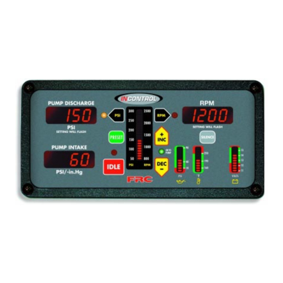
TGA100/TGA200 Rev0305 Controls and Indicators All controls and indicators are located on the front of the control module. (Refer to Figure 1.) The LED digital display has daylight bright digits at least 0.56 inch high. PUMP DISCHARGE Display Shows the pump discharge pressure during normal operations. PSI LED The red PSI LED is on to indicate operation in the pressure mode. -
Page 9: Figure 1. Controls And Indicators
TGA100/TGA200 Rev0305 INC Button During operations the button raises pressure or RPM setting. DEC Button During operations the button lowers pressure or RPM setting. OK TO PUMP Light This LED will be on when the required interlock conditions are met and the governor is ready to begin pump operations. -
Page 10: Installation
TGA100/TGA200 Rev0305 INSTALLATION When the governor is programmed at the factory there will be a label on the governor specifying the engine type. If there is no label on the governor the engine type must be verified/programmed per the Programming procedure. Install Control Panel 1. -
Page 11: Install Pressure Sensors
TGA100/TGA200 Rev0305 Install Pressure Sensors The two pressure sensors are mounted on the discharge and intake manifolds of the pump. If there is a check valve in the discharge side of the pump, mount the discharge transducer before the check valve. T-fittings can be used to mount the pressure transducers. -
Page 12: Install Engine Sensors
Install the buzzer close to the control panel so the audible warning is easily associated with the visual warning on the display. The optional buzzer provided by FRC requires a cutout hole of 1-1/8" (1.125"). Pin 7 on the 8-pin connector at the rear of the control module is provided to connect an optional buzzer. -
Page 13: Operation
TGA100/TGA200 Rev0305 OPERATION On power up the INControl will be in the pressure mode of operation. The RPM display will show IdLE. If there is a problem, the RPM display will show an error code. Refer to the Diagnostics section for error code descriptions. The minimum pump discharge pressure must be greater than 15 PSI for the INControl governor to take control of engine speed. -
Page 14: Pressure Mode Operation
TGA100/TGA200 Rev0305 Pressure Mode Operation In the pressure mode of operation the PSI LED will be on. The INControl will maintain a constant discharge pressure. It will adjust the engine RPM automatically to compensate for variations in pressure. Note: When changing from RPM mode to pressure mode the pressure setting will be the pressure that the pump was operating at in RPM mode. -
Page 15: Rpm Mode Operation
TGA100/TGA200 Rev0305 RPM Mode Operation In the RPM mode of operation the RPM LED will be on. The INControl will maintain a constant engine RPM. The pump discharge pressure can vary but, as a safety feature, the INControl limits the increase in pressure to 30 PSI. As the discharge pressure approaches this limit the INControl will automatically lower the RPM to prevent a high pressure surge. -
Page 16: High Idle
TGA100/TGA200 Rev0305 High Idle The INControl has a built in high idle function that can be used as necessary. A high idle switch needs to be installed that will provide a ground to pin 4 of the 8-pin connector. (Refer to Figure 5.) When the switch is closed, the high idle function will be engaged. - Page 17 TGA100/TGA200 Rev0305 This page intentionally left blank.
-
Page 18: Programming
TGA100/TGA200 Rev0305 PROGRAMMING This program information is provided for installers and should not be changed once the apparatus is put into service. The governor response speed may need to be adjusted if changes are made in the pump drive system after the governor is installed. Program Governor Response Speed Due to variations in pump drive systems the INControl program may be adjusted if necessary to improve performance. -
Page 19: Table 2. Engine Type Setting
TGA100/TGA200 Rev0305 Preliminary Set-up This procedure can be performed prior to installing the INControl on the apparatus. Connect 12 volt power as follows: 12-Pin connector pin 1 (red wire) +12 VDC 12-Pin connector pin 2 (black wire) Ground If the INControl is installed on the apparatus, turn on electrical power. Do not operate the engine. -
Page 20: Diagnostics
0 PSI, and calibrates the display to show 0. If there is pressure in the plumbing where the transducer is mounted this will cause the display to be calibrated to a false 0. To avoid this FRC recommends: Drain the pump and plumbing to ensure there is no residual pressure. -
Page 21: Table 3. Fault Codes
TGA100/TGA200 Rev0305 The information listed below is to aid in troubleshooting. Table 3. Fault Codes Code Problem Probable Cause >No voltage at the interlock input >Datalink cable not connected / No communication on incorrectly wired datalink >Broken wire / bad connector contact on datalink cable The engine is not >Broken wire / bad connector contact... -
Page 22: Wiring
TGA100/TGA200 Rev0305 WIRING The following figures include the schematics, wiring diagrams, block diagrams, and cables for the INControl. 12-Pin Connector For most electronic engines, the INControl receives engine RPM, oil pressure, and coolant temperature data over the J1587 databus from the engine ECM. Some engines do not broadcast this data over the databus and sensors may need to be installed. -
Page 23: 8-Pin Connector
TGA100/TGA200 Rev0305 8-Pin Connector 8 Pin Connector/Cable Wire Color Description +5 VDC Reference From ECM Black ECM Ground White Engine Control Signal To ECM White High Idle Black Buzzer Ground Blue Transmission Temp. Sensor 3-Wire Cable 8-Pin To Engine Control (See Engine Specific Wiring) Connector Provide Ground to... -
Page 24: Pressure Sensor
TGA100/TGA200 Rev0305 Pressure Transducer From Control Module 12-Pin Connector Pressure Transducer Cable Pressure Transducer Cable 3-Pin Sensor Connector Pin/Wire Description A/Black Ground B/Red Supply Voltage Pressure C/White Signal Output Transducer Ground Signal Output Supply Voltage Pressure Sensor (Top View) Figure 6. Pressure Transducer Wiring... - Page 25 TGA100/TGA200 Rev0305 This page intentionally left blank.
-
Page 26: Cummins Harness Connections
TGA100/TGA200 Rev0305 Cummins Harness Connections Interface Information The ECM Remote Accelerator (Throttle) Option has to be set to ON. The diagnostic tool cannot be used to do this, an Insight service tool must be used. Refer to an authorized dealer to program this option. ISB, ISC, and ISL Engine Interface 12-Pin J1587 (–) - Page 27 TGA100/TGA200 Rev0305 ISM Engine Interface 12-Pin J1587 DATALINK (–) Connector Black Wire J1587 DATALINK (+) (Refer to Red Wire Figure 4) ACCELERATOR SUPPLY RETURN 8-Pin Black Wire ACCELERATOR SUPPLY (+) Connector Red Wire REMOTE ACCELERATOR POSITION (Refer to White Wire Figure 5) REMOTE ACCELERATOR SWITCH ACCELERATOR GOVERNOR SWITCH...
-
Page 28: Detroit Diesel (Series 50 And 60) Harness Connections
TGA100/TGA200 Rev0305 Detroit Diesel (Series 50 and 60) Harness Connections Interface Information Connect the Engine Control extention cable to the Variable Speed Governor input on the engine ECM. There may be a 3-pin Packard connector (Variable Speed Governor Harness Connector installed by the chassis manufacturer) located behind the pump panel to plug into for the ECM connections. -
Page 29: Navistar And Detroit Diesel (Series 40) Harness Connections
TGA100/TGA200 Rev0305 Navistar and Detroit Diesel (Series 40) Harness Connections Interface Information The ECM must be programmed for a remote throttle input. Set PTO REMOTE PEDAL to 1. (This will enable the remote throttle input.) The VARIABLE PTO ENABLE input has to be at 12 VDC to activate the remote throttle. -
Page 30: Caterpillar Harness Connections
TGA100/TGA200 Rev0305 Caterpillar Harness Connections Interface Information The ECM Remote Throttle Option has to be enabled. Refer to an authorized dealer to program this option. 3116B, 3126B, 3176B, 3406E, C7, C10, C12 Engine Interface Engines with 70-pin OEM connector. J1587 Datalink J1587 Datalink 12-Pin Black Wire... - Page 31 TGA100/TGA200 Rev0305 3176B, 3406E, C10, C12 Engine Interface Engines with 40-pin OEM connector. J1587 Datalink J1587 Datalink Black Wire 12-Pin Negative (–) Connector J1587 Datalink Red Wire (Refer to Positive (+) Figure 4) Multi-Function Sensor 8-Pin Black Wire L901-GY Common Connector (Refer to Multi-Function Input #3...
- Page 32 TGA100/TGA200 Rev0305 Some Older Engine Interface Engines with 40-pin OEM connector. If the remote throttle option is not available in the ECM program, a relay needs to be installed to provide this capability. Wire the relay into the cab foot throttle harness, connect the InControl Engine Control cable, and supply 12 volts to the coil form the pump interlock circuit.
-
Page 33: Mercedes Harness Connections
TGA100/TGA200 Rev0305 Mercedes Harness Connections Interface Information J1587 Datalink 12-Pin J1587 (–) Black Wire Connector J1587 (+) Red Wire (Refer to Figure 4) Sensor Ground (Throttle Pedal & Remote) 21-Pin Connector 8-Pin Black Wire Connector Remote PTO Power Supply Red Wire (Refer to Remote Throttle Signal Analog White Wire... - Page 34 TGA100/TGA200 Rev0305 This page intentionally left blank.
-
Page 35: Flyback Diode Wiring
(seloniod coil, relay coil, electric motor winding, etc.). It is recommended that a flyback diode be installed on inductive devices that share a common power source/ ground with a FRC governor. Typical circuit showing a flyback diode installed across an inductive load.
Need help?
Do you have a question about the InControl TGA100 and is the answer not in the manual?
Questions and answers