Table of Contents

Related Manuals for FRC AUTOFOAM FS15


Summary of Contents for FRC AUTOFOAM FS15
- Page 1 FS15-60-120 Rev0204 AUTOMATIC AROUND-THE-PUMP FOAM SYSTEM MODEL: FS15, FS60, FS120 FIRE RESEARCH CORPORATION www.fireresearch.com 26 Southern Blvd., Nesconset, NY11767 TEL ( 631 ) 724-8888 FAX ( 631 ) 360-9727 TOLL FREE 1-800-645-0074...
-
Page 2: Table Of Contents
FS15-60-120 Rev0204 Table of Contents CONTENTS CONTENTS ....................... 2 List of Tables ......................2 List of Figures ....................... 2 INTRODUCTION ...................... 3 Overview ....................... 3 Features ......................... 3 Specifications ......................4 GENERAL DESCRIPTION ..................6 Components ......................6 Controls and Indicators ..................8 INSTALLATION ...................... -
Page 3: Introduction
FS15-60-120 Rev0204 INTRODUCTION Overview The AutoFoam is an around-the-pump foam proportioning metering system. It will automatically maintain a selected foam percent mixture regardless of water flow fluctuations. The AutoFoam is microprocessor controlled and is automatic in operation. The AutoFoam has easy to use controls and indicators. It becomes operational at the push of a single button. -
Page 4: Specifications
FS15-60-120 Rev0204 Specifications Power Supply Voltage: 12 VDC Nominal (24 VDC System Available) Supply Current: 1.5 Amp Maximum Foam Concentrate Induction FS120: 2 - 120 GPM FS60: 0.5 - 60 GPM FS15: 0.5 - 15 GPM Maximum Discharge Flow Rate FS120: 2200 GPM FS60:... - Page 5 FS15-60-120 Rev0204 Metering Valve Assembly Valve: Variable Orifice Linear Flow, With Position Sensing Flow Sensors: Paddlewheel Type Weight: 24 LBS Overall Length: 16.25" Overall Height: 10" Couplings FS120: 2.0" FS60: 1.5" FS15: 1.5" Eductor Material: Stainless Steel (304) Weight: 4.2 LBS Length FS120: 20"...
-
Page 6: General Description
FS15-60-120 Rev0204 GENERAL DESCRIPTION Components The AutoFoam system consist of the following components (Refer to Figure 1): Control Module Metering Valve Assembly Eductor Discharge Flow Sensor(s) and Sensor Housing(s) Summing Device Cables Control Module The control module is panel mounted and has a front bezel measuring 4.25 by 4.25 inches. -
Page 7: Figure 1. Plumbing Schematic
FS15-60-120 Rev0204 Figure 1. Plumbing Schematic... -
Page 8: Controls And Indicators
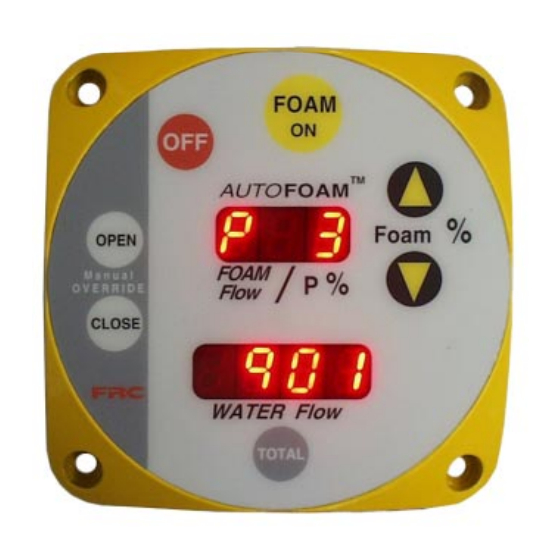
FS15-60-120 Rev0204 Controls and Indicators All controls and indicators are located on the front of the control module. It contains the push button electronic controls and digital displays. (Refer to Figure 2.) OFF Button Press this button to turn the AutoFoam system off. The metering valve will go to the closed position. -
Page 9: Figure 2. Controls And Indicators
FS15-60-120 Rev0204 FOAM Upper Button Button Display Increase Foam Percent Button FOAM Foam 0PEN M a n u a l FOAM O V E R R I D E Flow CLOSE Decrease WATER Flow Foam Percent Button TOTAL Manual TOTAL Lower OVERRIDE Button... -
Page 10: Installation
FS15-60-120 Rev0204 INSTALLATION Note: Plumbing systems are always unique and may cause small deviations in the factory calibration. It is recommended that the calibration procedure be performed after installation. Install Control Module 1. Measure and mark mounting location for control module panel cutout and mounting screw holes. -
Page 11: Figure 3. Control Module Dimensions
FS15-60-120 Rev0204 4.25" 1" 3.5" 4.5" 4.25" 3.75" 3.5" 10-32 Hardware Figure 3. Control Module Dimensions From Foam Tank Valve motor assembly Pump must be on top. Discharge Eductor Metering Valve Assembly Bypass and Flush Valves Pump Suction Interconnecting pipe diameters: FS120 system 2.0"... -
Page 12: Install Flow Sensor(S)
FS15-60-120 Rev0204 Install Flow Sensor(s) There are several ways to install FRC paddlewheel type flow sensors. Mounting options include saddle clamps, weldments, pipe tees, and special adapters. Each mount will meet particular plumbing requirements. The maximum pressure for a flow sensor installation is 600 PSI. -
Page 13: Figure 5. Flow Sensor Location Guidelines
FS15-60-120 Rev0204 The preferred location for the mounting of a flow sensor is on the top half of the pipe. The best orientation is vertical. If the sensor is mounted on the bottom of the pipe, it may be susceptible to the accumulation of dirt. - Page 14 FS15-60-120 Rev0204 Saddle Clamp Installation Note: Ensure that the mounting location meets the requirements for uniform water flow. (Refer to Flow Sensor Location.) Note: Ensure that there is enough room for the saddle clamp, sensor, and connector to fit. (Refer to Figure 6.) 1.
-
Page 15: Figure 6. Saddle Clamp Installation
FS15-60-120 Rev0204 Retainer Cap Pipe Size Dimensions (Sch 40) O-Ring Paddlewheel Flow Sensor Alignment Measurements are in inches. Sensor Housing Saddle Clamp Note: Allow a minimum of 2 inches clearence at the sensor top for removal/installation of the connector. Note: When the retainer cap is tightened make sure the sensor rim flat spot does not disengage from the alignment tab and... - Page 16 FS15-60-120 Rev0204 Weldment Installation Note: Ensure that the mounting location meets the requirements for uniform water flow. (Refer to Flow Sensor Location.) Note: Ensure that there is enough room for the weldment, sensor, and connector to fit. (Refer to Figure 7.) 1.
-
Page 17: Figure 7. Weldment Installation
FS15-60-120 Rev0204 Retainer Cap Pipe Size Dimension (Sch 40) 1.95 to 1.80 O-Ring 1.95 to 1.80 1.90 to 1.75 Paddlewheel 1.88 to 1.73 Flow Sensor 1.88 to 1.73 1.85 to 1.70 Measurements are in inches. Tru-Seal Locknut Alignment Make sure that the alignment tab is centered on the pipe centerline. -
Page 18: Install Summing Device
FS15-60-120 Rev0204 Install Summing Device The summing device mounts with two screws. Make sure there is room to connect the cables and adjust the potentiometers. Install Cables Cables need to be connected from the control module to power, to the metering valve, and to the summing device. -
Page 19: Figure 8. Cables
FS15-60-120 Rev0204 AUTOFOAM Red Wire 12VDC Black Wire Metering Valve and Dual Flow Sensors AutoFoam Summing Device Discharge Flow Multiple Discharge Sensor Flow Sensor Option Discharge Flow Summing Device Y-Cable Flow Discharge Flow Display Sensor Figure 8. Cables... -
Page 20: Theory Of Operation
FS15-60-120 Rev0204 THEORY OF OPERATION The operation of the AutoFoam system is controlled by a microprocessor housed in the control module. The programming enables the AutoFoam system to operate in three different modes. Automatic Mode This is the normal mode of operation. In this mode of operation the flow rate of foam concentrate is determined by the percent selected on the control module and inputs from the flow sensors. - Page 21 FS15-60-120 Rev0204 Foam concentrate flow rate greater than 9 GPM: If there is no output from the flow sensors a failure in the AutoFoam system is indicated. The upper display will show an E 2 code when the system is turned off to alert the operator that a failure occurred.
-
Page 22: Operation
FS15-60-120 Rev0204 OPERATION Static Operational Check This check should be performed after installation, maintenance, or repairs. It is a valuable tool if troubleshooting is necessary. It test the power and control module to metering valve wiring, and the manual operation of the metering valve. Note: Do not flow water or foam for this test. -
Page 23: Pump Intake And Discharge Pressure Requirements
FS15-60-120 Rev0204 Pump Intake and Discharge Pressure Requirements WARNING: If the recommended minimum pump discharge pressures are not adhered to, the foam system may operate at partial capacity or fail to inject foam. Note: It is recommended that standard operating procedure be to gate the pump input pressure at less than 20 PSI and adjust the discharge pressure to more than 140 PSI when foam is used. -
Page 24: Operational Check
FS15-60-120 Rev0204 Operational Check It is very expensive to use foam to test the system. As an alternative a die (e.g. red) can be used to color water in the foam tank. The color of the discharge allows the change in foam concentration to be observed. A lighter color indicates less foam in proportion to water while a darker color indicates more foam in proportion to water. -
Page 25: Figure 9. Sample Displays
FS15-60-120 Rev0204 AutoFoam system is off. Upper display shows OFF. FOAM Lower display is blank or if pump is running shows water flow at discharge sensor. Foam 0PEN M a n u a l FOAM O V E R R I D E Flow CLOSE WATER Flow... - Page 26 FS15-60-120 Rev0204 AutoFoam system is on. System is in Fixed Program mode. FOAM Upper display flashes showing –F– alternating with programmed foam flow rate. Foam 0PEN Lower display shows discharge flow. M a n u a l FOAM O V E R R I D E Flow Note: This condition CLOSE...
- Page 27 FS15-60-120 Rev0204 AutoFoam system is on. System is in Manual mode FOAM both upper and lower displays are flashing. Upper display shows foam flow. Foam Lower display shows 0PEN discharge flow. M a n u a l FOAM O V E R R I D E Flow CLOSE WATER Flow...
-
Page 28: Calibration
FS15-60-120 Rev0204 CALIBRATION The flow calibration potentiometers are located on the summing device. (Refer to Figure 10.) Note: Plumbing systems are always unique and may cause small deviations in the factory calibration. It is recommended that the calibration procedure be performed after installation. Calibrating Discharge Sensor(s) Note: For multiple discharge flow sensors calibrate each sensor separately. -
Page 29: Figure 10. Summing Device
FS15-60-120 Rev0204 6. Calculate the actual foam flow rate: Take the size of the foam tank (total gallon volume) divide it by the time it took to empty the tank. For best accuracy repeat the procedure 2 to 3 times. Ensure there is consistently in the result. (Do not average results that vary greatly from one another.) Example: (100 gallons/100 seconds) x 60 seconds/minute = 60 GPM This gives the actual foam flow rate. -
Page 30: Troubleshooting Tips
FS15-60-120 Rev0204 TROUBLESHOOTING TIPS Perform the Static Operational Check 1. If this check fails before step 8 the possible problems are: Power to the system Bad control module 2. If this check fails after step 8 the possible problems are: Wiring between the control module and the metering valve Bad control module Bad metering valve. -
Page 31: Maintenance
FS15-60-120 Rev0204 MAINTENANCE Flushing the System It is recommended that the system should be flushed after each use to remove the foam from the flow sensors, metering valve, and plumbing. Make sure that the valve to the foam tank is closed when flushing the metering valve so that no water gets into the foam tank. -
Page 32: Figure 11. Drawings
FS15-60-120 Rev0204 DRAWINGS Figure 11A. Eductor Drawing... - Page 33 FS15-60-120 Rev0204 Figure 11B. Metering Valve Drawing...
Need help?
Do you have a question about the AUTOFOAM FS15 and is the answer not in the manual?
Questions and answers