Table of Contents
Advertisement
Quick Links
Advertisement
Table of Contents

Related Manuals for Murphy ML2000


Summary of Contents for Murphy ML2000
- Page 1 Installation and Operations Manual 00-02-0994 2016-06-28 Section 40...
- Page 2 ML2000. Good engineering practices, electrical codes and insurance regulations require that you use independent external protective ML2000 can fail with outputs full ON, outputs full OFF or that other unexpected conditions can occur.
- Page 3 The ML2000 can be set as an AutoStart Controller. Please be cognizant at all times of hands and other objects that are in close proximity to the machine(s) being controlled as they may commence operation suddenly and without warning. LENS CLEANING PROCEDURES The lens on the display is composed of polycarbonate materials.
- Page 4 - THIS PAGE INTENTIONALLY LEFT BLANK - Section 40 00-02-0994 2016-06-28 - iv -...
-
Page 5: Table Of Contents
Table of Contents Introduction ..........................7 Mounting the Unit ......................7 Wiring ...........................9 Murphy PowerCore ® 20 (MPC-20) ................11 User Interface ......................13 Accessing the Menu ........................ 14 Main Menu ..........................15 Start/Stop Settings ........................19 Single Contact Start/Stop ................... 19 Two Contact Maintained Start/Stop (commonly known as Floats) ...... - Page 6 System ........................28 Engine Settings ......................29 Advanced Engine Settings ..................30 Throttle Menu ......................33 Input / Output Menu ....................33 Application Configuration ................... 37 Start / Stop Timers ..................... 39 Communication ......................40 Modbus Registers ...................... 40 Specifications ........................... 46 Electrical........................
-
Page 7: Introduction
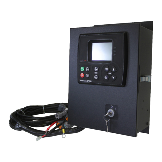
Introduction The Murphy Ready to Run family offers users a wide range of control and monitoring solutions for Isuzu engines. The Ready to Run Panel kits allow for a number of mounting configurations. The panels come ready, right out of the box for a quick and easy installation. - Page 8 ECU Mounting (4JJ1T and 4LE2) Accessories Description Part Number I/O Whip Harness for ML2000 panel 40000618 (10’ long, 31-position connector) I/O Connector Kit (31-position connector) 78700046 Section 40 00-02-0994 2016-06-28 - 8 -...
-
Page 9: Wiring
Wiring 4JJ1T Harness Section 40 00-02-0994 2016-06-28 - 9 -... - Page 10 4LE2 Harness Section 40 00-02-0994 2016-06-28 - 10 -...
-
Page 11: Murphy Powercore ® 20 (Mpc-20)
® 20 (MPC-20) The Murphy PowerCore 20 Controller (MPC-20) is a general all-purpose manual/auto start and manual/auto throttling engine controller. The controller is purposed primarily for pump and irrigation applications. However, it is versatile and flexible enough to be used on many applications outside pump and irrigation. This is a powerful controller that supports J1939 CAN protocols for electronically governed engines as well as mechanical engines for fault and safety shutdowns. - Page 12 • *Prestart Delay 2 (crank through): (available in Auto Mode only) After an auto start condition has been accepted by the controller, this delay begins timing, and the prestart output turns on. When this delay expires, the output remains on, and the auto sequence continues. The output turns off when the engine actually starts.
-
Page 13: User Interface
User Interface The keypad on the MPC-20 is comprised of 11 tactile buttons. This section describes the functions of each button. The buttons have the following functions: • Start Key – Allows the operator to start sequence in Manual Mode or initiate an auto start sequence when in Auto Mode. -
Page 14: Accessing The Menu
• Down Key – Allows the operator to navigate down through the menu and page reverse on the main pages. Accessing the Menu To access the MPC-20 menu, press the menu button: The following screen will display to enter the password (3482): The password will be entered left to right. -
Page 15: Main Menu
Main Menu The MPC-20 controller is incredibly versatile within the menu structure. The operator is able to change many parameters and settings from the face without the need of a PC tool, if desired. The controller has to be in its stopped state in order to change a setting in the menu. - Page 16 Throttle The Throttle menu allows the operator to set up the items for throttling the engine such as throttle type, rate of RPM increase/decrease, throttle Inc/Dec pulse time, throttle RPM deadband and other parameters pertaining to throttling of the engine. Review Throttle under the Menu Glossary section of this manual for a full list and definition of each setting.
- Page 17 Application Configuration The Application Configuration menu is where an operator will set up the controller’s Auto Start Functions and Auto Throttle Methods, if the intended use is as an auto start and/or auto throttling controller. Depending on which application is chosen in the menu, there are certain auto start functions and auto throttling methods hidden that are not pertinent to the application chosen.
- Page 18 The auto start functions and auto throttle methods to choose from are listed below. Auto Start/Stop Functions • Single Contact (will require a digital input for start and stop) • Two Contact Maintained (will require a digital input for start and stop) •...
-
Page 19: Start/Stop Settings
Communication The Communications menu allows the operator to choose the type of RS485 communications such as PVA Gauge, Modbus or Local Display. The menu also allows for the operator to choose the RS485 slave address, RS485 Serial setup and whether or not the controller uses the internal CAN terminating resistor. Review Communication under the Menu Glossary section of this manual for a full list and definition of each setting. -
Page 20: Quick-Start Setup Guide
Quick-Start Setup Guide The following sections serve to provide a walk-through of the steps necessary for some of the various configurations and settings available on the MPC-20 Controller. Cycling power to the controller is recommended after making changes to set points. Stepping through the Menu will be depicted as follows: Menu/System/Contrast directs the operator to go into the Menu first, then look for a parameter titled System and press [Enter] to go into the System menu. -
Page 21: Setting Mpc-20 To Auto Start On Pressure
Setting MPC-20 to Auto Start on Pressure 1. Access Menu/Application Configuration/Auto Start_Stop Function/Pressure Transducer, and press [Enter]. 2. Complete the parameters that apply (i.e., Maintain Pressure, High/Low Pressure, Start/Stop Pressure, etc.). 3. Press [Back] twice and access Input_Output/Analog Inputs. 4. Select an Analog Input to modify. 5. -
Page 22: Setting Mpc-20 To Stop The Engine From Utilizing The Countdown Timer
Setting MPC-20 to Stop the Engine from Utilizing the Countdown Timer The MPC-20 will control the running of the engine until the chosen stop condition is met or until the countdown timer runs out of time. Once set, the operator will be required to disable or change the timer in order to eliminate the countdown timer being active on every startup. -
Page 23: Mpc-20 Screens In Order
MPC-20 Screens in Order This is the main screen, and it displays actual and target RPM, Oil Pressure, Engine Temperature, Battery Voltage, Engine Hours, Engine State and Mode of Operation. This screen is the first six-up screen, and it displays Oil Temperature, Fuel Level, Torque, Fuel Rate, Suction and Discharge to the operator. - Page 24 This screen is the second six-up screen, and it displays to the operator System Level, Pump Oil, Fuel Temperature, Ambient (temperature) and Flow Rate (gpm). If alternate parameters are desired, these may be changed within the free MPC-20 Software Configuration tool. This screen displays the auto start/stop type and will also illustrate the throttling method for the auto start/stop.
- Page 25 This screen displays the date, day, time, software version number, configuration revision number, engine manufacturer, part number (if available) and serial number (if available). This page will assist Technical Services Support should their services be needed. This screen will allow the operator to see what the digital output functions are set to without accessing the menu and the active setting which informs the user of the output status.
- Page 26 This screen will allow the operator to see what the relay status functions are set to without accessing the menu and the active setting which informs the user of the relay status. This screen will allow the operator to see what the digital input functions are set to without accessing the menu and the active setting which informs the user of the input status.
-
Page 27: Warning And Shut-Down Icons
This screen provides a list of service reminders and the hours left until the internal alarm will display the services needed. When 0 hours is reached, the hours will continue to count down in negative numbers. Warning and Shut-Down Icons The following icons can be displayed at the bottom of the MPC-20 screen to designate that a warning or shut- down situation has occurred: Icon... -
Page 28: Menu Glossary
Menu Glossary System Date/Time: allows the setting of the controller’s date and time. Pressure Units: allows the selection of psi, kPa or BAR for pressure designation. Factory set to PSI. Temperature Units: allows the selection of Fahrenheit or Celsius for temperature designation. Factory set to Fahrenheit. -
Page 29: Engine Settings
Engine Settings Engine Type: allows the selection between J1939 and Mechanical. If Mechanical is chosen, some parameters associated with J1939 will no longer appear in the menu. Factory set to J1939. Engine Manufacturer: allows the selection of the specific Engine Manufacturer (i.e., Caterpillar, Cummins, John Deere, Deutz, Kubota, Yanmar, JCB, Volvo, FPT, Isuzu, Other). -
Page 30: Advanced Engine Settings
Low Battery Warning: allows the operator to select the desired warning in the controller for Low Battery to alert the operator when the voltage of the battery is too low. Factory set to 10.0 V. Weak Battery Warning: allows the operator to select the desired warning in the controller for Weak Battery to alert the operator when the battery is becoming too weak to function. - Page 31 Crank Time: length of time the crank output is turned on during cycle cranking. Factory set to 00.00.10 Crank Rest: length of time the crank output is turned off during cycle cranking. Factory set to 00.00.10 Prestart Delay 1: after an auto start condition has been accepted by the controller, this delay begins timing, and the prestart #1 output turns on.
- Page 32 Warnings and Shutdowns: establish parameters for the: Low Fuel Level Warning: sounds a warning when the fuel level reaches the set lower limit parameter. Factory set to 10% Low Fuel Level Shutdown: shuts down the engine when the fuel level reaches the set lower limit parameter.
-
Page 33: Throttle Menu
Overspeed Shutdown: shuts down the engine when the speed reaches the set higher limit parameter for speed. Factory set to 2400 RPM. Throttle Menu Throttle Type: allows the selection of J1939 TSC1, Pulse Inc/Dec or Analog 0-5VDC as the throttle type for the engine. - Page 34 Digital input 1. Factory set to Disabled Digital Input 2. Factory set to Auto Start Momentary/Maintained Digital Input 3. Factory set to Auto Stop Momentary/Maintained Digital Input 4. Factory set to Low Coolant Level Digital Input 5. Factory set to Low Lube Oil Level Digital Input 6.
- Page 35 Murphy Oil Temp Datcon Oil Temp VDO Oil Temp Murphy Discharge Pressure Murphy Suction Pressure Datcon Pump Housing Temp Murphy Pump Housing Temp VDO Pump Housing Temp Murphy Pump Oil Temperature Datcon Pump Oil Temperature VDO Pump Oil Temperature Murphy PMK-400 Pressure Analog.Digital1...
- Page 36 Coolant Temp (0-5V) or (4-20mA) Discharge Pressure (0-5V) or (4-20mA) Fluid Pressure (0-5V) or (4-20mA) Fuel Level (0-5V) or (4-20mA) Oil Temp (0-5V) or (4-20mA) Pump Housing Temp (0-5V) or (4-20mA) Pump Oil Temp (0-5V) or (4-20mA) Suction Pressure (0-5V) or (4-20mA) By raising the minimum value (5mA or 1V) in the sensor setup, a negative Suction Pressure can be read by the Controller.
-
Page 37: Application Configuration
Throttle Increase / Throttle Decrease The increase and decrease outputs are used for the pulse inc/dec throttling type. Digital Input (1-6) A digital input can be assigned to turn on a digital output. Analog (1-8) Digital An analog input configured to be a digital input can be assigned to turn on a digital output. - Page 38 Pressure Transducer Maintain Pressure. The engine will be throttled between the min. and max. RPM set points to maintain this pressure. Factory set to 0 psi. Deadband Pressure. This extends above and below the maintain set point, no throttling occurs while the pressure is in the deadband.
-
Page 39: Start / Stop Timers
starting and stopping on flow. 0 gpm must be selected in the maintain flow for the steady/proportional features to work. Factory set to Steady. Deadband Flow. This extends above and below the maintain set point, no throttling occurs while the flow in the deadband. -
Page 40: Communication
Days of the week are factory set to Off. Start and stop Times are factory set to 12.00.00 AM. Start Day Sunday Monday Tuesday Wednesday Thursday Friday Saturday Daily Start Time: format of HH:MM:SS Stop Day: Sunday Monday Tuesday Wednesday Thursday Friday Saturday... - Page 41 REGISTER # TYPE DESCRIPTION 40005 Read Only Current Oil Pressure 40006 Read Only Current Engine Temperature 40007 Read Only Current Engine State: ECU Stabilize Delay timing: (1) yes (0) no Engine Stopped: (1) yes (0) no Controller in Standby Mode: (1) yes (0) no Prestart Delay 1 Timing: (1) yes (0) no Check Safe to Start: (1) yes (0) no Prestart 2 Delay Timing: (1) yes (0) no...
- Page 42 REGISTER # TYPE DESCRIPTION Bit 3 High Flow SD Status: (1) yes (0) no Bit 4 Low Flow SD Status: (1) yes (0) no Bit 5 High Pump Oil Temperature SD Status: (1) yes (0) no Bit 6 High Pump Housing Temperature SD Status: (1) yes (0) no Bit 7 Water in Fuel SD Status: (1) yes (0) no Bit 8...
- Page 43 REGISTER # TYPE DESCRIPTION 40211 Read Only J1939.Engine.Diesel Particulate Filter 1 Soot Load Percent. 40212 Read Only J1939.Transmit.Diesel Particulate Filter Regeneration Inhibit Switch 40213 Read Only J1939.Engine.Diesel Particulate Filter Active Regen Inhibited Due to Inhibit Switch (LSB) Inhibited Due to Inhibit Switch: (1) yes (0) no Reserved Reserved Reserved...
- Page 44 REGISTER # TYPE DESCRIPTION 40228 Read Only Service Reminder: Battery Life Remaining 40229 Read Only Service Reminder: Belt Life 40230 Read Only Service Reminder: Belt Life Remaining 40231 Read Only Service Reminder: Fuel Filter Life 40232 Read Only Service Reminder: Fuel Filter Life Remaining 40233 Read Only Service Reminder: Oil Filter Life...
- Page 45 Enable Disable PC Configuration Software The MPC-20 controller is the first engine controller released utilizing Murphy’s PowerVision Configuration Studio ® software. With PowerVision, engineering will be able to deliver quicker software updates with the flexibility of a software developer’s environment. The new addition of PowerVision to this controller gives Enovation Controls the ability to provide a free-of-charge basic PC configuration program to change default parameters in the controller to all customers.
-
Page 46: Specifications
Specifications Electrical Display: 3.8” monochrome, transflective, white backlight LCD with heater Operating Voltage: 8-32 VDC, protected against reverse battery polarity and load-dump Power Consumption: 18W max without 2 2A High-sides active, 146W max with 2 2A High-sides active Communications 2-CAN: J1939 (only one supported in initial release) USB: 2.0B (only supported for programming) Ethernet: (not supported in initial release) RS485: Modbus RTU... - Page 47 -THIS PAGE INTENTIONALLY LEFT BLANK-...
Need help?
Do you have a question about the ML2000 and is the answer not in the manual?
Questions and answers