
Related Manuals for AE AIR50-2230A

Summary of Contents for AE AIR50-2230A
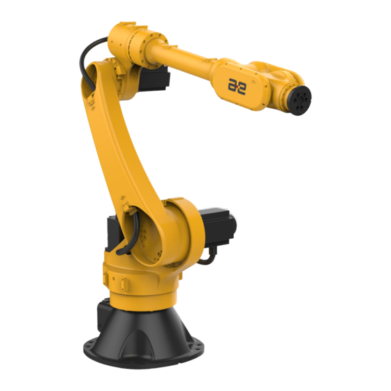
- Page 1 Peitian Robot AIR50-2230A | Operation Manual Equipment manufacturing industry A solution provider for intelligent...
- Page 2 AIR50-2230A Operation Manual V 1.4...
-
Page 3: Sign
Chinese Government. In addition, when the product is re-exported to other countries, the Government undefined permission to re-export the product should be obtained. To export or re-export such products, please contact the AE Group. -
Page 4: The Identity Used In This Article
AIR50-2230A Operation Manual The identity used in this article The identity used in this article The marks and their meanings are shown in Table 1. Table 1 Common identifiers in this article Sign Name specification Failure to operate in accordance with the... -
Page 5: General Safety Description
AIR50-2230A Operation Manual General safety description General safety description Thank you for purchasing our operator. this description is required for the safe use of the operator. Before using the operator, please read the manual carefully and use the operator correctly on the premise of understanding it. - Page 6 AIR50-2230A Operation Manual General safety description The State party points out a supplementary note other than warning and ◼ attention. General considerations Warning ◼ When connecting or disconnecting relevant peripheral equipment(such as safety fence, etc.)and various signals of the operator, make sure that the operator is in the stop state to avoid wrong connection.
- Page 7 AIR50-2230A Operation Manual General safety description Considerations during installation Warning When handling and installing the machines, they must be carried out ◼ correctly according to the method shown in our manual. If the operation is carried out in the wrong way, it is possible that the operator will be killed or injured due to the overturning of the operator.
- Page 8 AIR50-2230A Operation Manual General safety description Considerations in programming Warning When the safety fence is to be programmed, as much as possible outside ◼ the safety fence, the following matters shall be taken into account when the safety fence needs to be carried out as a last resort: Check the safety fence carefully and make sure it is not dangerous before entering the fence.
- Page 9 AIR50-2230A Operation Manual General safety description Attention should be paid to maintenance work. Warning When switching on the power supply, part of the maintenance operation ◼ is in danger of electric shock, as far as possible, the maintenance operation should be carried out in the state of disconnecting the operator and the system power supply;...
- Page 10 AIR50-2230A Operation Manual General safety description Warning When carrying out maintenance operations, when it is necessary to move ◼ the operator as a last resort, the following matters should be taken into account: It is important to ensure that the escape channel is smooth and that...
- Page 11 AIR50-2230A Operation Manual General safety description Decelerator Adjacent to motor / reduce Inside the control cabinet Warning The parts (such as screws, etc.) removed during the replacement of the ◼ parts should be correctly loaded back to their original parts, and if the parts are found to be insufficient or surplus, they should be reconfirmed and installed correctly.
- Page 12 AIR50-2230A Operation Manual General safety description Warning When carrying out maintenance operations, appropriate lighting ◼ appliances should be equipped, but care should be taken not to make the lighting appliances a source of new danger. Warning Be sure to refer to this specification for regular maintenance, if not ◼...
-
Page 13: Safety Protection Measures Before Use
AIR50-2230A Operation Manual Safety Protection Measures before Use Safety Protection Measures before Use Before running the manipulator and peripheral equipment and the whole system, be sure to fully study the safety protection measures of operator and system. Safe operation of industrial robot is as shown in Figure 1-1. - Page 14 AIR50-2230A Operation Manual Safety Protection Measures before Use Safety of Operation Personnel Operator, teacher and maintenance engineer shall carefully perform the operation, programming and maintenance of manipulator, and shall at least wear the following items: Work clothes suitable for task ◼...
- Page 15 AIR50-2230A Operation Manual Safety Protection Measures before Use Safety of Operators Operators are not authorized to perform jobs within the safety barrier: Disconnect the power supply of manipulator control cabinet or press the ◼ emergency stop button when the manipulator is not operated.
- Page 16 AIR50-2230A Operation Manual Safety Protection Measures before Use 5.Execute the program in automatic operation mode。 ◼ The teacher must evacuate outside the safety fence when the operator operates automatically. Safety of Repair Engineer To ensure the safety of repair engineer, full attention shall be paid to the following items: Never enter the range of manipulator while the manipulator is running.
- Page 17 AIR50-2230A Operation Manual Safety Protection Measures before Use ◼ In case of abnormalities of other manipulators or peripheral equipment, the measures shall be taken, such as stopping the manipulator, even if there is no abnormality in the manipulator. For the system of which the manipulator is operating synchronously with ◼...
- Page 18 AIR50-2230A Operation Manual Safety Protection Measures before Use difference from the issuance to the actual action and conduct the control with certain room of extension and retraction. A detection unit shall be set on the end effector to monitor the status of end...
-
Page 19: Table Of Contents
Basic Composition ............................5 Basic Specifications ............................6 Environmental Requirements for Operation ...................... 7 The label name and meaning of AIR50-2230A ................8 Safety sign of manipulator ..........................8 Manipulator nameplate ............................8 Direction Sign of Each Axle ..........................9 AIR50-2230A Transport and Handing .................. - Page 20 Catalogue Electrical Interface Type for Manipulator ....................... 21 Definitions of Heavy-duty ..........................21 Adaptation and connection of AIR50-2230A manipulator and accessories ........23 Examples of accessory types ........................23 Connection mode ............................24 Performance parameters of AIR50-2230A manipulator ..............25 Basic specification ............................
- Page 21 AIR50-2230A Operation Manual Catalogue Appendix B Table of screw strength and tightening torque (Nm) ............75...
-
Page 23: Product Overview
AIR50-2230A Operation Manual Product overview 1 Product overview 1.1 Product purpose and content The product is written so that the technician can install and use the operator quickly, correctly and safely, be familiar with the relevant precautions and do regular maintenance work on the operator. -
Page 24: Declaration Of Compliance With Product Standards
AIR50-2230A Operation Manual Product overview Declaration of compliance with product standards The requirements for industrial robot system design are detailed in Table 1-2. Table 1-2 Declaration of Applicable Safety Standards Standard Description Version Machinery directive : Machinery directive 2006/42/EC (new version) issued... - Page 25 AIR50-2230A Operation Manual Product overview 标准 说明 版本 Electromagnetic compatibility (EMC): Part 6-2: Generic standards - Immunity for industrial 61000-6-2 2005 environments Electromagnetic compatibility (EMC): Part 6-4: Generic standards - Emission standard for 61000-6-4 + A1 2011 industrial environments Safety of machinery:...
-
Page 26: Air50-2230A Robot Overview And Basic Composition
AIR50-2230A Operation Manual AIR50-2230A robot overview and basic composition 2 AIR50-2230A robot overview and basic composition 2.1 Overview of Industrial Robot Figure 2-1 shows an example of Industrial robot consists of the following parts: Manipulator ◼ Control cabinet ◼ Teach pendant ◼... -
Page 27: Basic Composition
(tools or workpieces), also known as the robot body. This manipulator is the 6-DOF tandem industrial robot that consists of three swing axes and three rotating axes. AIR50-2230A robot manipulator and the names of its various parts are as shown in Figure 2-2. J6 flange interface... -
Page 28: Basic Specifications
AIR50-2230A Operation Manual AIR50-2230A robot overview and basic composition 2.3 Basic Specifications The basic specifications of AIR50-2230A robot manipulator are as shown in 。 Table 2-1 Table 2-1 Basic Specifications of AIR50-2230A AIR50-2230A Coordinate form 6-DOF articulated robot Number of control axes... -
Page 29: Environmental Requirements For Operation
AIR50-2230A Operation Manual AIR50-2230A robot overview and basic composition Environmental Requirements for Operation Temperature ➢ The range of ambient temperature for AIR50-2230A manipulator is as shown in Table 2-2: Table 2-2 Temperature Limits Requirement Value (° C) Min. temperature Max. temperature Humidity ➢... -
Page 30: The Label Name And Meaning Of Air50-2230A
AIR50-2230A Operation Manual The label name and meaning of AIR50-2230A 3 The label name and meaning of AIR50-2230A 3.1 Safety sign of manipulator No Approaching An operator safety label shall be pasted on the back of the upper arm of the operator. -
Page 31: Direction Sign Of Each Axle
AIR50-2230A Operation Manual The label name and meaning of AIR50-2230A Figure 3-2 Robot nameplate 3.3 Direction Sign of Each Axle “+” or “-” sign is provided at the rotating or swinging joints of axes 1~6 of manipulator as shown in Figure 3-3 to indicate the moving direction of each axle. -
Page 32: Air50-2230A Transport And Handing
Do not use forklift and other grippers to apply impact force to the delivery ◼ support Do not put chains on delivery support ◼ 4.1 Handing Posture AIR50-2230A manipulator during handling shall be posed as shown in Table 4-1。 Table 4-1 Angle Values of Axes for Robot during Handling -35° 170° 60°... -
Page 33: Handing Dimensions
AIR50-2230A Operation Manual AIR50-2230A Transport and Handing 35° 60° 10° Figure 4-2 Handling Posture of AIR50-2230A Manipulator Warning ◼ Manipulator shall be handled in strict accordance with the posture in the table, otherwise it may fall due to unstable center of gravity. -
Page 34: Handing With Forklift
AIR50-2230A Operation Manual AIR50-2230A Transport and Handing Figure 4-3 Dimensions of AIR50-2230A Manipulator during the Handling Process 4.3 Handing with Forklift Handling with forklift is as shown in Figure 4-4. Forklift shall meet the requirement for the weight of manipulator. The total weight of manipulator and handling device is about 260kg。... -
Page 35: Handing With Swinging Ring
The total weight of manipulator and handling device is about 260kg。 4-M20 lifting bolt Figure 4-5 AIR50-2230A Manipulator Handling with Swinging Ring Caution When manipulator is handled with swinging ring, insert a soft object ◼... -
Page 36: Preparation Before Installation
AIR50-2230A Operation Manual Preparation before Installation 5 Preparation before Installation 5.1 Check Item Following requirements shall be strictly adhered to before installation: ◼ Ensure that the installers pass the relevant training of company and perform the installation according to the international and local laws and regulations. - Page 37 AIR50-2230A Operation Manual Preparation before Installation Chapter 6.2 Several round pins (Ф 10 mm). Please see in this manual for ◼ details.
-
Page 38: Installation Of Air50-2230A Manipulator
Enough thought shall be given to the strength of foundation installation surface for the installation of manipulator. The installation ground inclination shall be less than 5° for manipulator Dimensions of AIR50-2230A manipulator base are as shown in Figure 6-1: 8-Φ22 through-hole 15°... - Page 39 The names and specifications of parts required to fix the manipulator are as shown in Table 6-1 Table 6-1 Parts for Fixing AIR50-2230A Manipulator Bracket Part Name Remarks Ground fixing fixing Four M20x40 (Grade 12.9) 4...
- Page 40 AIR50-2230A Operation Manual Installation of AIR50-2230A manipulator Prompt ◼ Fixing plate surface shall meet certain roughness and flatness ◼ requirements as detailed in Figure 6-2 Figure 6-3 8-M20 chemical bolt Φ750 45° Figure 6-2 Operator fixing mode 1 M20X40 screw...
- Page 41 AIR50-2230A Operation Manual Installation of AIR50-2230A manipulator ➢ Bracket fixing Bracket fixing process (mode 2) is as follows: Install the manipulator base on the bracket with eight M20x40 bolts (Grade 12.9)。Mounting surface of bracket shall meet certain flatness requirements as shown in Figure 6-4.
- Page 42 AIR50-2230A Operation Manual Installation of AIR50-2230A manipulator Figure 6-5 Operator fixing mode 2 Warning Fixing screw M20 of manipulator shall not be shorter than 40 mm, and ◼ the insufficient length will cause the poor fixing and other accidents. When installing the manipulator ceiling, the length of fixing screws for ◼...
-
Page 43: Electrical Connection Of Air50-2230A Manipulator
Electrical connection of AIR50-2230A manipulator 7 Electrical connection of AIR50-2230A manipulator 7.1 Electrical Interface Type for Manipulator Aviation plug and heavy-duty connector r are provided on the AIR50-2230A manipulator base as shown Figure7-1. From left to right model is WEIN HDD-042 and HF24B module. - Page 44 AIR50-2230A Operation Manual Electrical connection of AIR50-2230A manipulator Caution When the robot is connected, pay attention to the one-to-one ◼ correspondence between the heavy loads on the body and those on the control cabinet...
-
Page 45: Adaptation And Connection Of Air50-2230A Manipulator And Accessories
Adaptation and connection of AIR50-2230A manipulator an AIR50-2230A Operation Manual d accessories 8 Adaptation and connection of AIR50-2230A manipulator and accessories 8.1 Examples of accessory types The accessory equipment of the manipulator mainly includes mechanical grab (Figure 8-1), hydraulic pressure sucker (Figure 8-2), welding gun welder (Figure 8-3), infrared identification equipment, visual identification equipment, cutting machine, other special equipment, etc. -
Page 46: Connection Mode
The definition of heavy-duty connector on the control cabinet of AIR50-2230A operator is shown in Figure 8-4 below. For more details, please refer to the corresponding manual of the electrical part. -
Page 47: Performance Parameters Of Air50-2230A Manipulator
AIR50-2230A manipulator. 9.2 Dimension and working range of each axis The motion range of each axis of AIR50-2230A manipulator is shown in Table as follows: Table 9-1 Motion range of each axis of AIR50-2230A manipulator motion range(°... -
Page 48: Mechanical Limit
185° R2238 185° Figure 9-1 Working range of AIR50-2230A Manipulator 9.3 Mechanical limit Zero point and movable range are respectively set on each axle. Robot is limited to the movable range except that the origin position is lost due to the servo system abnormality and system error. -
Page 49: Speed Of Each Axis
The maximum angular speed of each axis of the manipulator is shown in Table Table 9-2 Maximum angular speed of each axis of the manipulator Axis number Maximum angular velocity(° /s) 9.5 Output flange size Figure 9-3 show output flange connection size of AIR50-2230A. - Page 50 Performance parameters of AIR50-2230A manipulator Φ6 H7 depth5 Φ100 6-M8 depth16 Figure 9-3 The flange dimension diagram of wrist of AIR50-2230A manipulator show output flange specification of AIR50-2230A. Tightening Table 9-3 torque of screws is shown in Appendix B: Table 9-3 The output mechanical interface specifications of AIR50-2230A...
-
Page 51: Load And Installation Method
Figure 9-4 Location of wrist load center of AIR50-2230A Manipulator for data of load torque and load rotational inertia of AIR50-2230A Table 9-4 manipulator Table 9-4 Data of load torque and load rotational inertia of AIR50-2230A manipulator Model of axis Load torque... - Page 52 The specification and size of the installation hole of J3 axis elbow of AIR50-2230A manipulator are shown in Figure 9-5. Figure 9-5 Interface dimension diagram of elbow load of AIR50-2230A manipulator See Figure 9-6 for the specification and size of the installation hole of the...
- Page 53 Performance parameters of AIR50-2230A manipulator Installation of elbow equipment of axis 3 of AIR50-2230A manipulator,the following should be noted: The elbow and wrist of AIR50-2230A manipulator can be equipped with ◼ external equipment with a weight of no more than 20kg.
- Page 54 4-M8depth16 300± 0.05 150± 0.1 Figure 9-7 Interface dimension drawing of AIR50-2230A manipulator jib When installing the equipment, the reliability of installation shall be fully considered. It is recommended to use 12.9 grade screws to install according to the specified torque, and apply thread glue on the thread, otherwise the long-term operation may lead to looseness or even fracture, resulting in accidents.
-
Page 55: Calibration Of The Axes Of The Air50-2230A Manipulator
AIR50-2230A Operation Manual Calibration of the axes of the AIR50-2230A manipulator Calibration of the axes of the AIR50-2230A manipulator General 10.1 This section describes the case where the manipulator needs to be calibrated and the zero calibration method under different requirements. - Page 56 According to the zero point calibration position shown in Figure 10-1 AIR50-2230A zero point diagram of each axis, the naked eye shall be used to make the zero point position of each shaft to be aligned, as shown in Figure...
- Page 57 AIR50-2230A Operation Manual Calibration of the axes of the AIR50-2230A manipulator Observe the alignment of zero calibration position of each axis Figure 10-2 Calibration method of naked eye observation zero Warning In the calibration process of the manipulator, the speed should be ◼...
- Page 58 AIR50-2230A Operation Manual Calibration of the axes of the AIR50-2230A manipulator Calibration for rough requirements for path positioning accuracy When the path positioning accuracy is roughly required, the calibration block is used, as shown in Figure 10-3. 、 J3 Calibration...
-
Page 59: Calibrate The Direction Of Motion Of Each Axis
AIR50-2230A Operation Manual Calibration of the axes of the AIR50-2230A manipulator inserted into the two calibration grooves at the same time after multiple fine adjustment, as shown in Figure 10-3. Calibration under the requirement of High path Positioning accuracy When the operator is required to have high path positioning accuracy, it is... - Page 60 AIR50-2230A Operation Manual Calibration of the axes of the AIR50-2230A manipulator bottom, the axis 1 ,axis 4,axis 6 counter-clockwise movement is positive, clockwise is negative.
-
Page 61: General Principles Of Maintenance
AIR50-2230A Operation Manual General principles of maintenance General principles of maintenance This manual is a description of preventive maintenance of AIR50-2230A operators. For the maintenance of a complete set of industrial robot systems, it should also include: Control cabinet maintenance-see "Control cabinet maintenance manual". - Page 62 AIR50-2230A Operation Manual General principles of maintenance In order to avoid unnecessary pollution caused by the impurities such as ◼ dust, the outside shall be cleaned before opening the control cabinet door and the outer cover of the operating machine.
-
Page 63: Maintenance Items
AIR50-2230A Operation Manual Maintenance Items Maintenance Items Daily maintenance 12.1 When running the operator every day, the following items should be checked. As shown in Table 12-1 Table 12-1 Daily Maintenance of Operation Machine Ordinal Inspection item Main points of inspection... - Page 64 AIR50-2230A Operation Manual Maintenance Items Ordinal Inspection item Main points of inspection Whether the terminal Inspect the cable for damage, and the cable actuator cable is sheath is damaged damaged or not Whether the Check if the synchronous belt is worn, elongated,...
-
Page 65: Regular Maintenance
AIR50-2230A Operation Manual Maintenance Items The external connecting screws of the manipulator, especially the ◼ connecting screws of each shaft to the reducer or gearbox. For the tightening torque, refer to the values recommended in the ◼ appendix to this specification. - Page 66 AIR50-2230A Operation Manual Maintenance Items Ordinal Inspection item Main points of inspection If there is a lot of dust stuck to the vent Control cabinet vent cleaning of the control cabinet, please remove it Wipe away dirt, remove accumulated Cleaning of operators spatter, dust, dust, chips, etc.
- Page 67 AIR50-2230A Operation Manual Maintenance Items Ordinal Inspection item Main points of inspection damaged or not 7860 hours (2 years) regular maintenance The operation machine shall be operated for 2 years or 7860 hours (whichever is short), and the following items shall be inspected and repaired. As shown in...
- Page 68 AIR50-2230A Operation Manual Maintenance Items 19200 hours (5 years) regular maintenance For every 5 years or 19200 hours (whichever is the shorter time), the operator needs to be overhauled and many parts need to be replaced. Please contact us. As shown in...
-
Page 69: Project Maintenance Process
AIR50-2230A Operation Manual Project Maintenance Process Project Maintenance Process Cleaning of Manipulator 13.1 To ensure the long-term operation of robot, the manipulator shall be cleaned every 960 h or 3 months (whichever comes first) according to the following process: Adjust the robot to the calibration state. - Page 70 AIR50-2230A Operation Manual Project Maintenance Process Wrist Cable J3 Cable fix J2 Cable fix Base internal Cable Figure 13-1 Layout for Cables of manipulator Check and Overhaul Process for external Cables check and repair process as follows: Adjust the manipulator from J1 to J6's angle is 0° ,0° ,90° ,-180° ,0° ,0° .
- Page 71 AIR50-2230A Operation Manual Project Maintenance Process Check and repair process for internal cables of base Check and repair process as follows: Remove the electrical mounting plate as shown inFigure 13-2, and pull out the internal cables of base. Check if the fixing plate secures the cables on the mounting plate.
- Page 72 AIR50-2230A Operation Manual Project Maintenance Process Check and Repair Process for Internal Cables of the wrist Check and Repair Process as follows:: Remove the cover plate as shown in Figure 13-3. Check the fixation between the cable and bracket for wear or damage.
-
Page 73: Battery Replacement
AIR50-2230A Operation Manual Project Maintenance Process Battery Replacement 13.3 The data on the positions of manipulator axes is saved with the encoder battery. The battery shall be replaced according to the following process every 7,860 h or 2 years (whichever comes first) or in case of A2 alarm from drive. -
Page 74: Grease Replacement
AIR50-2230A Operation Manual Project Maintenance Process Grease replacement 13.4 Operation machine J1 axis to J6 axis reducer, every 11520 hours or 3 years (whichever is shorter), need to replace the internal grease. Grease type and grease quantity, please refer to... - Page 75 AIR50-2230A Operation Manual Project Maintenance Process Open the drain carefully and slowly to prevent oil spatter. ◼ J1 axis reducer replacement grease process Grease Outlet Grease Injection Figure 13-5 Replace J1 shaft reducer grease The replacement process is as follows:...
- Page 76 AIR50-2230A Operation Manual Project Maintenance Process Remove the grease injector, install the M10x1 plug on the grease outlet and grease injector, and apply the sealing tape/sealant. Caution ◼ When injecting fat from the fat injection port into the inner part of the operation machine, the fat injection speed by hand pump is less than 8g/s and the fat injection pressure is less than 0.3mpa.In order to ensure the...
- Page 77 AIR50-2230A Operation Manual Project Maintenance Process Install grease drain tubing to ensure waste oil flows into the sump tank. Remove the grease injection port M10x1 plug, install the grease injection nozzle, and use manual grease injection gun to inject grease until the new grease is discharged from the outlet.
- Page 78 AIR50-2230A Operation Manual Project Maintenance Process The replacement process is as follows: Run the manipulator as shown in Table 13-2 To prevent danger, turn off the power, hydraulic and pneumatic sources connected to the robot. Place the sump tank for collecting waste oil near the grease outlet.
- Page 79 AIR50-2230A Operation Manual Project Maintenance Process J4 axis gear case and reducer replacement grease process Grease Grease Outlet Grease Outlet Injection Grease Injection Figure13-8 Replace J4 shaft gearbox and reducer grease The replacement process is as follows: Run the manipulator as shown in Table 13-2 To prevent danger, turn off the power。...
- Page 80 AIR50-2230A Operation Manual Project Maintenance Process Grease Outlet Grease Injection Figure13-10 Replace J5 shaft reducer grease The replacement process is as follows: Run the manipulator as shown in Table 13-2. To prevent danger, turn off the power。 Remove the grease outlet plug, as shown in figure 13-9 Remove the sealing screw of grease outlet and Grease Injection, as shown in fig.13-10.
- Page 81 AIR50-2230A Operation Manual Project Maintenance Process Install the sealing screw and apply sealant. Release grease pressure inside reducer When releasing the inner grease pressure of the reducer, please install the recovery device at the outlet of the exhaust grease to avoid the splash of the grease and the pollution of the environment..
-
Page 82: Replacement Of Synchronous Belt
AIR50-2230A Operation Manual Project Maintenance Process Replacement of Synchronous Belt 13.5 Synchronous belt of J5 axis shall be replaced every 11520h or 13year (whichever comes first) : For the model of synchronous belt, please seem Table 13-4 Table 13-4 Synchronous Belt Model for Manipulator... - Page 83 AIR50-2230A Operation Manual Project Maintenance Process Install the cover plate of manipulator and coat the joint with sealant. Perform the calibration for J5 axis of manipulator. M4 screw Cover plate Figure 13-12Removal of Cover Plate M5 screw M5 screw motor...
-
Page 84: Common Faults And Treatment
AIR50-2230A Operation Manual Common Faults and Treatment Common Faults and Treatment The fault of manipulator may be caused by a number of different reasons. It is often difficult to thoroughly find out the cause. If the wrong handling method is used, the fault may be further deteriorated. - Page 85 AIR50-2230A Operation Manual Common Faults and Treatment Fault Classification Possible Causes Treatment ◼ Confirm whether Vibration at a specific manipulator load exceeds the posture during the action allowable value, and reduce Load manipulator ◼ No vibration at the the load or change the action...
- Page 86 AIR50-2230A Operation Manual Common Faults and Treatment Fault Classification Possible Causes Treatment 1. Fault of the circuit inside 1. For the fault of controller, the controller, failure of see the controller manual command to transmit to the 2. Replace the motor of...
- Page 87 AIR50-2230A Operation Manual Common Faults and Treatment Fault Classification Possible Causes Treatment ◼ Abnormal noise after replacement 1. Abnormal noise from the lubricating grease manipulator at low speed 1.Observe the operation of Vibration ◼ immediately after manipulator for 1-2 days.
- Page 88 AIR50-2230A Operation Manual Common Faults and Treatment Fault Classification Possible Causes Treatment Control Parameter: Enter appropriate ◼ Motor overheats after 1. Improper input parameters parameters according to the action control will cause the incorrect relevant instructions. parameters of manipulator acceleration and deceleration...
- Page 89 AIR50-2230A Operation Manual Common Faults and Treatment Fault Classification Possible Causes Treatment 1. The damage of brake drive 1. Check if the brake drive relay causes the brake to relay is damaged, and if so, always be powered on and ◼...
-
Page 90: Conditions Of Storage
AIR50-2230A Operation Manual Conditions of Storage Conditions of Storage Environmental Conditions for Long-term Storage of Manipulator 15.1 For the purpose of long-term storage, the manipulator shall be placed in a cool place that is protected from direct sunlight and water. The specific... - Page 91 AIR50-2230A Operation Manual Conditions of Storage When the storage period is over and the manipulator is put into the operation again, the manipulator shall be checked in accordance with Chapter 5.1 of this manual...
-
Page 92: Options List Of Product
AIR50-2230A Operation Manual Options List of Product Options List of Product Figure 16-1 Options List of Industrial Robot System Type of industrial robot and control cabinet: AIR6-1450A+inCube20 AIR3-560A + inCube10 AIR6-A+ inCube10 AIR6P+ARCC6P AIR20-1700A+ inCube10 ... - Page 93 AIR50-2230A Operation Manual Options List of Product without nameplate AE(standard) Background picture of teach pendant: AE(standard) OEM______ Logo of teach pendant shell: without AE Logo AE(standard) Options of control cabinet: Logo of circuit board: without AE Logo AE(standard) Nameplate of control cabinet: without nameplate AE(standard)...
-
Page 94: Appendix A Periodic Maintenance Schedule Of Air20-1700A Manipulator
AIR50-2230A Operation Manual Appendix A Periodic Maintenance Schedule of AIR50-2230A Manipulator Appendix A Periodic Maintenance Schedule of AIR20-1700A Manipulator Schedule A Periodic Maintenance Schedule Of AIR20-1700A Manipulator First month month 1 year month month month 2 year month month month... - Page 95 AIR50-2230A Operation Manual Appendix A Periodic Maintenance Schedule of AIR50-2230A Manipulator First month month 1 year month month month 2 year month month month 3 year month month month 4 year month month month 5 year Maintenan month Maintenan Item...
- Page 96 AIR50-2230A Operation Manual Appendix A Periodic Maintenance Schedule of AIR50-2230A Manipulator First month month 1 year month month month 2 year month month month 3 year month month month 4 year month month month 5 year Maintenan month Maintenan Item...
- Page 97 Appendix B Table Of Screw Strength And Tightening Torq AIR50-2230A Operation Manual ue (Nm) Appendix B Table Of Screw Strength And Tightening Torque (Nm) Appendix B Table of screw strength and tightening torque(Nm) Performance level 8.8 level 10.9 level 12.9 level...
Need help?
Do you have a question about the AIR50-2230A and is the answer not in the manual?
Questions and answers