
Subscribe to Our Youtube Channel
Related Manuals for AE AIR20-A

Summary of Contents for AE AIR20-A
- Page 1 Sign Manipulator Manual of AIR20-A Industrial Robot Peitian Robot AIR20-A | Manipulator Manual...
-
Page 2: Sign
Sign Manipulator Manual of AIR20-A Industrial Robot Sign Before using an industrial robot, be sure to read the manual carefully and use it correctly while understanding its content. Nothing in this manual shall be reproduced or transmitted in any way. -
Page 3: The Identity Used In This Article
The identity used in this article Manipulator Manual of AIR20-A Industrial Robot The identity used in this article The marks and their meanings are shown in Table 1. Table 1 Common identifiers in this article 标志 名称 含义 Failure to operate in... -
Page 4: General Safety Description
General safety description Manipulator Manual of AIR20-A Industrial Robot General safety description Thank you for purchasing our operator. this description is required for the safe use of the operator. before using the operator, please read the manual carefully and use the operator correctly on the premise of understanding it. - Page 5 General safety description Manipulator Manual of AIR20-A Industrial Robot Prompt The State party points out a supplementary note other than warning and attention. General considerations Warning When connecting or disconnecting relevant peripheral equipment(such as safety fence, etc.)and various signals of the operator, make sure that the operator is in the stop state to avoid wrong connection.
- Page 6 General safety description Manipulator Manual of AIR20-A Industrial Robot Prompt Personnel who carry out programming and maintenance operations must receive appropriate training through the relevant training of the company. Considerations during installation Warning When handling and installing the machines, they must be carried out ...
- Page 7 General safety description Manipulator Manual of AIR20-A Industrial Robot Prompt Information such as programs and system variables can be stored in storage media such as memory cards. In order to prevent data loss caused by unexpected accidents, it is recommended that users back up data regularly.
- Page 8 General safety description Manipulator Manual of AIR20-A Industrial Robot Attention should be paid to maintenance work. Warning When switching on the power supply, part of the maintenance operation is in danger of electric shock, as far as possible, the maintenance operation should be carried out in the state of power off;...
- Page 9 General safety description Manipulator Manual of AIR20-A Industrial Robot Warning When carrying out maintenance operations, when it is necessary to move the operator as a last resort, the following matters should be taken into account: It is important to ensure that the escape channel is smooth and that...
- Page 10 General safety description Manipulator Manual of AIR20-A Industrial Robot Warning The following parts will be hot and need attention. When you have to touch the equipment when you have to touch it in the event of heat, you should prepare protective appliances such as heat-resistant gloves:...
- Page 11 General safety description Manipulator Manual of AIR20-A Industrial Robot Warning When replacing parts, dust and other foreign bodies should be prevented from entering the manipulator. Warning Operators who carry out maintenance and repair operations must receive the training of the company and pass the relevant assessment.
-
Page 12: Safety Protection Measures Before Use
Safety Protection Measures before Use Manipulator Manual of AIR20-A Industrial Robot Safety Protection Measures before Use Before running the manipulator and peripheral equipment and the whole system, be sure to fully study the safety protection measures of operator and system. Safe operation of industrial robot is as shown in Fig.1。... - Page 13 AIR20-A 系列工业机器人操作机手册 Safety Protection Measures before Use Perform the maintenance (repair, adjustment, replacement, etc.) of manipulator Safety of Operation Personnel Operator, teacher and maintenance engineer shall carefully perform the operation, programming and maintenance of manipulator, and shall at least...
- Page 14 Safety Protection Measures before Use Manipulator Manual of AIR20-A Industrial Robot manipulator, the audible and visual alarms such as the buzzer are issued to stop the manipulator, thereby ensuring the safety of operation personnel. A lock shall be set if possible to make sure that the manipulator power cannot be turned on except by the operation personnel responsible for the operation.
- Page 15 AIR20-A 系列工业机器人操作机手册 Safety Protection Measures before Use Teachers shall pay special attention to make other people away from the range of manipulator Before starting the manipulator, first confirm that there is no people and no abnormality in the range of manipulator.
- Page 16 Safety Protection Measures before Use Manipulator Manual of AIR20-A Industrial Robot When the manipulator is equipped with a tool, and there are movable devices such as conveyor belts in addition to the manipulator, pay attention to the operation of these devices.
- Page 17 AIR20-A 系列工业机器人操作机手册 Safety Protection Measures before Use Limit switches and mechanical brakes shall be used to limit the operation of manipulator to avoid the collisions between the manipulator and peripheral equipment. User cables and hoses shall not be added to the manipulator.
-
Page 18: Table Of Contents
..........................4 ASIC PECIFICATIONS ........................5 NVIRONMENTAL EQUIREMENTS FOR PERATION ..................6 THE LABEL NAME AND MEANING OF AIR20-A ................8 AFETY SIGN OF MANIPULATOR ......................8 ANIPULATOR NAMEPLATE ......................... 8 IRECTION IGN OF ......................9 AIR20-A TRANSPORT AND HANDING ...................10... - Page 19 ......................... 28 PEED OF EACH AXIS ........................29 UTPUT FLANGE SIZE ........................29 OAD AND INSTALLATION METHOD ....................... 30 CALIBRATION OF THE AXES OF THE AIR20-A MANIPULATO ............35 10.1 ENERAL ............................35 10.2 HEN CALIBRATION IS REQUIRED ......................35 10.3...
-
Page 20: Air20-A Product Overview
Manipulator Manual of AIR20-A Industrial Robot AIR20-A Product overview 1 AIR20-A Product overview 1.1 Product purpose and content The product is written so that the technician can install and use the operator quickly, correctly and safely, be familiar with the relevant precautions and do regular maintenance work on the operator. -
Page 21: Declaration Of Compliance With Product Standards
Manipulator Manual of AIR20-A Industrial Robot AIR20-A Product overview Declaration of compliance with product standards The requirements for industrial robot system design are detailed in Table 1-2。 Declaration of Applicable Safety Standards Table 1-2 Standard Description Version Machinery directive :... - Page 22 Manipulator Manual of AIR20-A Industrial Robot AIR20-A Product overview Standard Description Version Electromagnetic compatibility (EMC): 61000-6-2 Part 6-2: Generic standards - Immunity for 2005 industrial environments Electromagnetic compatibility (EMC): 61000-6-4 + A1 Part 6-4: Generic standards - Emission standard for...
-
Page 23: Air20-A Robot Overview And Basic Composition
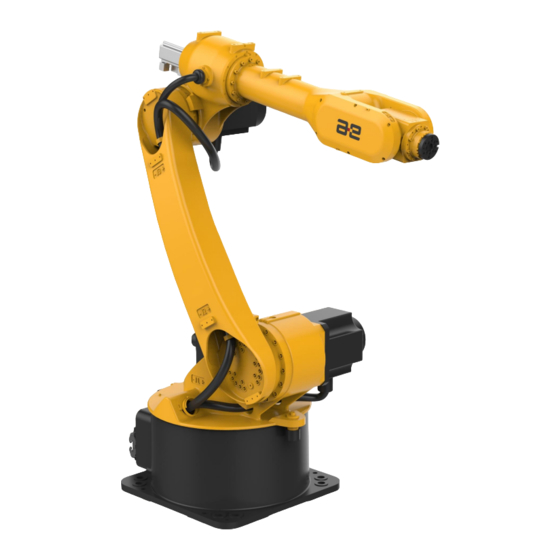
(tools or workpieces), also known as the robot body. This manipulator is the 6-DOF tandem industrial robot that consists of three swing axes and three rotating axes. AIR20-A robot manipulator and the names of its various parts are as shown in Fig. 2-2. -
Page 24: Basic Specifications
AIR20-A robot overview and basic composition Robot Body and Its Various Parts Fig. 2-2 AIR20-A 2.3 Basic Specifications The basic specifications of AIR20-A robot manipulator are as shown in Table 2-1. Table 2-1 Basic Specifications of AIR20-A AIR20-A Coordinate form... -
Page 25: Environmental Requirements For Operation
“ * ” If the mechanical limit of J1 axle is removed, the range may reach -185° to 185°。 2.4 Environmental Requirements for Operation Temperature The range of ambient temperature for AIR20-A manipulator is as shown in Table 2-2. Table 2-2 Temperature Limits Requirement Value (° C) Min. temperature Max. - Page 26 Manipulator Manual of AIR20-A Industrial Robot AIR20-A robot overview and basic composition Resistance to vibration Robot manipulator shall be used in an environment where there is no vibration. The limit frequency of ambient vibration is 22 Hz and the amplitude shall not exceed 0.15 mm.
-
Page 27: The Label Name And Meaning Of Air20-A
Manipulator Manual of AIR20-A Industrial Robot The label name and meaning of AIR20-A 3 The label name and meaning of AIR20-A 3.1 Safety sign of manipulator An operator safety label shall be pasted on the back of the upper arm of the operator. -
Page 28: Direction Sign Of Each Axle
Manipulator Manual of AIR20-A Industrial Robot The label name and meaning of AIR20-A 3.3 Direction Sign of Each Axle “+” or “-” sign is provided at the rotating or swinging joints of axes 1~6 of manipulator as shown in Fig. 3-3 to indicate the moving direction of each Joint. -
Page 29: Air20-A Transport And Handing
Manipulator Manual of AIR20-A Industrial Robot AIR20-A Transport and Handing 4 AIR20-A Transport and Handing Caution Manipulator shall be equipped with the matching handling bracket. The incorrect handling method may cause the damage to manipulator. Manipulator posture during handling is subject to the description in Chapter 4.1 Handing Dimensions of this manual Precautions for... - Page 30 Manipulator Manual of AIR20-A Industrial Robot AIR20-A Transport and Handing Fig. 4-2 Dimensions of AIR20-A Manipulator during the Handling Process Fig. 4-3 Dimensions of AIR20-A Manipulator during the Handling Process...
-
Page 31: Handing Posture
Fig. 4-4 Dimensions of AIR20-A Manipulator during the Handling Process 4.2 Handing Posture One to six axis posture of AIR20-A manipulator during handling shall be posed as shown in Table 4-1 and Fig. 4-5. Table 4-1 Angle Values of Axes for Robot during Handling -65°... -
Page 32: Handing With Forklift
Handling with forklift is as shown in Fig. 4-6. Forklift shall meet the requirement for the weight of manipulator. The total weight of manipulator and handling device is about 260kg. Fig. 4-6 Schematic Diagram of AIR20-A Handling with Forklift Caution Manipulator shall be equipped with the matching handling bracket. The ... - Page 33 Manipulator Manual of AIR20-A Industrial Robot AIR20-A Transport and Handing Fig. 4-7 Schematic Diagram of AIR20-A Manipulator Handling with Swinging Ring Caution When manipulator is handled with swinging ring, insert a soft object between the sling and manipulator to avoid the scratching on the manipulator body by sling.
-
Page 34: Air20-A Preparation Before Installation
Manipulator Manual of AIR20-A Industrial Robot AIR20-A Preparation before Installation 5 AIR20-A Preparation before Installation 5.1 Check item Following requirements shall be strictly adhered to before installation: Ensure that the installers pass the relevant training of company and perform the installation according to the international and local laws and regulations. -
Page 35: Installation Of Air20-A Manipulato
Manipulator quality 260kg 57kg(20kg+12kg+25kg) Total weight of load Dimensions of AIR20-A manipulator base are as shown in Fig. 6-1. Fig. 6-1 Dimensions of AIR20-A Manipulator Base Interface 6.2 Fixed mode Three ways of fixing are suitable for AIR20-A manipulator: Ground fixing (mode 1). - Page 36 Manipulator Manual of AIR20-A Industrial Robot Installation of AIR20-A manipulato Prompt Specific fixing mode depends on the usage environments. Strength of chemical bolt is subject to the strength of concrete. Therefore, the safety shall be fully considered according to the design guidelines of manufacturer before the construction.
- Page 37 Manipulator Manual of AIR20-A Industrial Robot Installation of AIR20-A manipulato Install the manipulator base on the fixing plate with four M20x40 bolts (Grade 12.9). bolts M20X40 Manipulator base Robot fixed plate M20 chemical bolts Concrete for manipulator Fig. 6-2 The fixed mode 1...
- Page 38 Manipulator Manual of AIR20-A Industrial Robot Installation of AIR20-A manipulato Lift mounting Lift mounting process (mode 2) is as follows: Hold the fixing plate of robot close to the mounting surface and secure it with eight M20 chemical bolts (strength not less than Grade 4.8).
- Page 39 Manipulator Manual of AIR20-A Industrial Robot Installation of AIR20-A manipulato Bracket fixing Bracket fixing process (mode 3) is as follows: Fix the 4 mounting brackets with 8 M20 chemical bolts (strength grade not less than 4.8). Install the manipulator base on the bracket with eight M20x40 bolts (Grade 12.9).
- Page 40 Manipulator Manual of AIR20-A Industrial Robot Installation of AIR20-A manipulato Warning Fixing screw M20 of manipulator shall not be shorter than 40 mm, and the insufficient length will cause the poor fixing and other accidents. When installing the manipulator ceiling, the length of fixing screws for ...
-
Page 41: Electrical Connection Of Air20-A Manipulator
Fig. 7-1 The heavy-duty connector on AIR20-A manipulator body 7.2 Definitions of Heavy-duty Interfaces of Manipulator Heavy-duty interface of AIR20-A manipulator is defined as shown in Table 7-1 and Table 7-2. Table 7-1 Pin definition of Heavy duty power line... - Page 42 Manipulator Manual of AIR20-A Industrial Robot Electrical connection of AIR20-A manipulator Pin number Definition Internal cables Use the pin yellow and green CEM-1.5 (J2) black 1(J2) CEM-1.5 black 2(J2) CEM-1.5 black 3(J2) CEM-1.5 yellow and green CEM-1.5 (J1) black 1(J1)...
- Page 43 Manipulator Manual of AIR20-A Industrial Robot Electrical connection of AIR20-A manipulator Pin number Definition Internal cables Use the pin gray(J5) J5_0V CAM-08 green(J5) J5_PS+ CAM-08 yellow(J5) J5_PS- CAM-08 J6_5V pink(J6) CAM-08 J6_0V gray(J6) CAM-08 J6_PS+ green(J6) CAM-08 yellow(J6) J6_PS- CAM-08...
-
Page 44: Adaptation And Connection Of Air20-A Manipulator And Accessories
Adaptation and connection of AIR20-A manipulator and accessori Manipulator Manual of AIR20-A Industrial Robot 8 Adaptation and connection of AIR20-A manipulator and accessories 8.1 Examples of accessory types The accessory equipment of the operator mainly includes mechanical grab (Fig. 8-1), hydraulic pressure sucker (Fig. 8-2), welding gun welder (Fig. 8-3), infrared identification equipment, visual identification equipment, cutting machine, other special equipment, etc. -
Page 45: Connection Mode
The definition of heavy-duty connector on the control cabinet of AIR20-A manipulator is shown in Fig. 8-4 below. For more details, please refer to the corresponding manual of the electrical part. -
Page 46: Performance Parameters Of Air20-A Manipulator
See Chapter 2.3 Basic Specifications of this manual for the basic specifications of AIR20-A manipulator 9.2 Dimension and working range of each axis The motion range of each axis of AIR20-A manipulator is shown in Table 9-1 as follows. Table 9-1 motion range of each axis of AIR20-A manipulator axis number motion range(°)... -
Page 47: Mechanical Limit
Manipulator Manual of AIR20-A Industrial Robot Performance parameters of AIR20-A manipulator Fig. 9-1 working range of AIR20-A Manipulator 9.3 Mechanical limit Zero point and movable range are respectively set on each Joint. Robot is limited to the movable range except that the origin position is lost due to the servo system abnormality and system error. -
Page 48: Speed Of Each Axis
Table 9-2 maximum angular speed of each axis of the manipulator Maximum angular velocity(°/s) axis number 9.5 Output flange size The Table 9-3 and Fig. 9-3 show output flange specification and connection size of AIR20-A. Tightening torque of screws is shown in Appendix B. -
Page 49: Load And Installation Method
9.6 Load and installation method Wrist load installation of manipulator The wrist load line diagram of AIR20-A manipulator is shown in Fig. 9-4. The load conditions shall be within the limits shown on the chart. ... - Page 50 Please refer to Table 2-1 for specific values. Fig. 9-4 location of wrist load center of AIR20-A Manipulator Installation of elbow equipment of axis 3 of manipulator The specification and size of the installation hole of J3 axis elbow of AIR20-A manipulator are shown in Fig. 9-5.
- Page 51 Manipulator Manual of AIR20-A Industrial Robot Performance parameters of AIR20-A manipulator The elbow and wrist of AIR20-A manipulator can be equipped with external equipment with a weight of no more than 12kg. The position of center of mass of elbow load shall be located in the area of 150mm ×...
- Page 52 See Fig. 9-6 for the specification and size of the installation hole of the manipulator jib. Fig. 9-6 interface dimension drawing of AIR20-A manipulator jib Fixed position of the manipulator boom and the j1axis body. See Fig.9-7 for the specification and size of the installation hole of the manipulator jib Fig.
- Page 53 Manipulator Manual of AIR20-A Industrial Robot Performance parameters of AIR20-A manipulator Fig. 9-8 interface dimension diagram of AIR20-A j1axis body Warning When installing the equipment, the screw used shall take full account of the depth of the threaded hole, and the installation length shall not exceed the depth of the threaded hole, otherwise the internal components or cables of the operator will be damaged.
-
Page 54: Calibration Of The Axes Of The Air20-A Manipulato
Manipulator Manual of AIR20-A Industrial Robot Calibration of the axes of the AIR20-A manipulato 10 Calibration of the axes of the AIR20-A manipulato 10.1 General This section describes the case where the manipulator needs to be calibrated and the zero point calibration method under different requirements. - Page 55 The robot calibration must always be performed at the same temperature conditions to avoid errors due to thermal expansion and contraction. Caution The AIR20-A industrial robot calibration must be calibrated in sequence from the J1 axis to the J6 axis. Calibration required for high repetitive positioning accuracy...
- Page 56 Manipulator Manual of AIR20-A Industrial Robot Calibration of the axes of the AIR20-A manipulato Calibration for rough requirements for path positioning accuracy When the path positioning accuracy is roughly required, the calibration block is used, as shown in Fig. 10-3.
-
Page 57: General Principles Of Maintenance
Manipulator Manual of AIR20-A Industrial Robot General principles of maintenance 11 General principles of maintenance This manual is a description of preventive maintenance of AIR20-A operators. For the maintenance of a complete set of industrial robot systems, it should also include: Control cabinet maintenance-see "Control cabinet maintenance manual". -
Page 58: Maintenance Items
Manipulator Manual of AIR20-A Industrial Robot Maintenance Items 12 Maintenance Items 12.1 Daily maintenance When running the operator every day, the following items should be checked. As shown in Table 12-1. Table 12-1 Daily Maintenance of Operation Machine Ordinal Inspection item... - Page 59 Manipulator Manual of AIR20-A Industrial Robot Maintenance Items Ordinal Inspection item Main points of inspection Clean and maintain the parts of the All parts of the manipulator, and check whether the parts are cleaning manipulator damaged (Note 3). Whether the terminal...
-
Page 60: Regular Maintenance
Manipulator Manual of AIR20-A Industrial Robot Maintenance Items The external connecting screws of manipulator, especially the connecting screws of shaft and the reducer or gearbox. For the tightening torque, please refer to the values suggested in the appendix of this manual. - Page 61 Manipulator Manual of AIR20-A Industrial Robot Maintenance Items Ordinal Inspection item Main points of inspection Wipe away dirt, remove Cleaning of operators accumulated spatter, dust, dust, chips, etc. 1920 hours (6 months) regular maintenance The operation machine shall run for 1920 hours or 6 months (whichever is shorter), and the following items shall be inspected and repaired.
- Page 62 Manipulator Manual of AIR20-A Industrial Robot Maintenance Items Ordinal Inspection item Main points of inspection Chapter First Whether the J1 shaft limit rubber block 12.2 maintenance is damaged or not 7860 hours (2 years) regular maintenance The operation machine shall be operated for 2 years or 7860 hours (whichever is short), and the following items shall be inspected and repaired.
- Page 63 Manipulator Manual of AIR20-A Industrial Robot Maintenance Items 19200 hours (5 years) regular maintenance For every 5 years or 19200 hours (whichever is the shorter time), the operator needs to be overhauled and many parts need to be replaced. Please contact us.
-
Page 64: Project Maintenance Process
Manipulator Manual of AIR20-A Industrial Robot Project Maintenance Process 13 Project Maintenance Process 13.1 Cleaning of Manipulator To ensure the long-term operation of robot, the manipulator shall be cleaned every 960 h or 3 months (whichever comes first) according to the following process: Adjust the robot to the calibration state. - Page 65 Manipulator Manual of AIR20-A Industrial Robot Project Maintenance Process Wrist Cable J3 Cable fix J2 Cable fix Base internal Cable Fig. 13-1 Layout for Cables of manipulator Check and repair process for internal cables of base check and repair process as follows: Adjust the manipulator from J1 to J6's angle is 0°,0°,90°,-...
- Page 66 Manipulator Manual of AIR20-A Industrial Robot Project Maintenance Process Check the fixation between the cables and fixing plate for wear or damage. Check the internal cables for wear or damage.. In case of crack, wear or damage, please contact us for replacement timely.
- Page 67 Manipulator Manual of AIR20-A Industrial Robot Project Maintenance Process Check whether the cable and the bracket are fixed for wear or damage. Inspect internal cables for wear and tear. In case of cracks, wear or damage, please contact us for replacement.
-
Page 68: Battery Replacement
Manipulator Manual of AIR20-A Industrial Robot Project Maintenance Process In case of crack, wear or damage, please contact us for replacement timely. Check if the lubricating grease on the internal cable surface has disappeared. If so, it shall be replenished timely. -
Page 69: Replace Grease
Manipulator Manual of AIR20-A Industrial Robot Project Maintenance Process Remove the battery cover on the electrical mounting plate of manipulator as shown in Fig. 13-5. Remove the old battery from the box and put the new battery into the box. Be sure to keep the positive and negative polarities of battery same as the old one. - Page 70 Manipulator Manual of AIR20-A Industrial Robot Project Maintenance Process Table 13-2 grease changing attitude of operator13-2 Replace the grease part 170 ° 0 ° 90 ° J1 axis reducer 0 ° 0 ° 90 ° J2 axis reducer 0 °...
- Page 71 Manipulator Manual of AIR20-A Industrial Robot Project Maintenance Process Install grease drain tubing to ensure waste oil flows into the sump tank. Remove the grease injection port M10x1 plug, install the grease injection nozzle, and use manual grease injection gun to inject grease until the new grease is discharged from the outlet.
- Page 72 Manipulator Manual of AIR20-A Industrial Robot Project Maintenance Process J2 axis reducer replacement grease process Grease Outlet Grease Injection Fig. 13-7 replace the grease of J2 axis reducer The replacement process is as follows: Run the manipulator as shown in Table 13-2.
- Page 73 Manipulator Manual of AIR20-A Industrial Robot Project Maintenance Process Caution When injecting fat from the fat injection port into the inner part of the operation machine, the fat injection speed by hand pump is less than 8g/s and the fat injection pressure is less than 0.3mpa.In order to ensure the...
- Page 74 Manipulator Manual of AIR20-A Industrial Robot Project Maintenance Process Release the grease pressure inside the reducer as shown in Table 13-3. The amount of oil discharged by weighing shall be equal to the amount of oil injected. If the discharge amount is less than the injection amount, the excess amount is discharged by gas at the fat injection port.
-
Page 75: Replacement Of Synchronous Belt
Manipulator Manual of AIR20-A Industrial Robot Project Maintenance Process Caution Improper fat-feeding operations may cause a sharp increase in the pressure in the reducer or gearbox, damaging internal parts such as the sealing ring, resulting in oil leakage or poor operation. - Page 76 Manipulator Manual of AIR20-A Industrial Robot Project Maintenance Process Replacement Process for Synchronous Belt of J5 and J6 Axes Replacement as follows: Run the manipulator to the posture as shown in Table 13-5. Turn off the power of controller.
- Page 77 Fig. 13-11 Installation Deflection of Synchronous Belt Warning After the replacement of synchronous belt, the J5 and J6 axes of manipulator shall be calibrated. For details, see Chapter 10 Calibration of the axes of the AIR20-A manipulato of this manual。...
-
Page 78: Common Faults And Treatment
Manipulator Manual of AIR20-A Industrial Robot Common Faults and Treatment 14 Common Faults and Treatment The fault of manipulator may be caused by a number of different reasons. It is often difficult to thoroughly find out the cause. If the wrong handling method is used, the fault may be further deteriorated. - Page 79 Manipulator Manual of AIR20-A Industrial Robot Common Faults and Treatment Fault Classification Possible Causes Treatment Vibration 1. Confirm whether the specific posture during the manipulator load exceeds 1. Load of manipulator action the allowable value, and exceeds allowable ...
- Page 80 Manipulator Manual of AIR20-A Industrial Robot Common Faults and Treatment Fault Classification Possible Causes Treatment 1. Fault of the circuit inside the controller, failure of 1. For the fault of controller, command to transmit to see the controller manual the motor, or the motor 2.
- Page 81 Manipulator Manual of AIR20-A Industrial Robot Common Faults and Treatment Fault Classification Possible Causes Treatment Abnormal noise after replacement 1. Abnormal noise from the lubricating grease manipulator at low speed 1.Observe the operation of Abnormal noise Vibration immediately after manipulator for 1-2 days.
- Page 82 Manipulator Manual of AIR20-A Industrial Robot Common Faults and Treatment Fault Classification Possible Causes Treatment motor, thus preventing the motor from overheating. 5. Please consult with us Control Parameter: Improper input 1. Enter the appropriate Motor overheats parameters will cause the...
- Page 83 Manipulator Manual of AIR20-A Industrial Robot Common Faults and Treatment Fault Classification Possible Causes Treatment 1. The damage of brake drive relay causes the 1. Check if the brake drive brake always relay is damaged, and if so, brake...
-
Page 84: Conditions Of Storage
Before the long-term storage of manipulator, it shall be posed for handling and placed on the horizontal surface. For details, see Chapter 4 AIR20-A Transport and Handingof this manual When the manipulator is not in use for a long time, cut off all powers, unplug the heavy-duty connector on the body, and cover the heavy-duty connector. - Page 85 Manipulator Manual of AIR20-A Industrial Robot Conditions of Storage The manipulator surface shall be cleaned regularly for dust and pollutant with the specific cleaning cycle depending on the storage environment of manipulator. When the storage period is over and the manipulator is put into the operation again, the manipulator shall be checked in accordance with Chapter 5.1 Check item of this manual...
-
Page 86: Options List Of Product
Manipulator Manual of AIR20-A Industrial Robot Conditions of Storage Options List of Product Fig 16-1 Options List of Industrial Robot System Type of industrial robot and control cabinet: AIR6ARC-A+inCube20 AIR3-A+ inCube10 AIR6-A+ inCube10 AIR6P+ARCC6P AIR20-A+ inCube10 ... - Page 87 Manipulator Manual of AIR20-A Industrial Robot Conditions of Storage Nameplate of teach pendant:: without nameplate AE(standard) Background picture of teach pendant: AE(standard) OEM______ Logo of teach pendant shell: without AE Logo AE(standard) Options of control cabinet: Logo of circuit board:...
- Page 88 Manipulator Manual of AIR20-A Industrial Robot Conditions of Storage without AE Logo AE(standard) ...
-
Page 89: Appendix A Periodic Maintenance Schedule Of Air20-A Manipulator
Appendix A Periodic Maintenance Schedule of AIR20-A Manipulator Manipulator Manual of AIR20-A Industrial Robot Appendix A Periodic Maintenance Schedule of AIR20-A Manipulator Schedule A Periodic Maintenance Schedule of AIR20-A Manipulator First month month 1 year month month month 2 year... - Page 90 Appendix A Periodic Maintenance Schedule of AIR20-A Manipulator Manipulator Manual of AIR20-A Industrial Robot First month month 1 year month month month 2 year month month month 3 year month month month 4 year month month month 5 year Maintenan...
- Page 91 Appendix A Periodic Maintenance Schedule of AIR20-A Manipulator Manipulator Manual of AIR20-A Industrial Robot First month month 1 year month month month 2 year month month month 3 year month month month 4 year month month month 5 year Maintenan...
-
Page 92: Appendix B Table Of Screw Strength And Tightening Torque (Nm)
AIR20-A 工业机器人操作机手册 Appendix B Table of screw strength and tightening torque (Nm) Appendix B Table of screw strength and tightening torque(Nm) Performance level Thread 8.8 level 10.9 level 12.9 level specification 0.35 0.48 0.56 M2.5 0.68 0.93 12.5 Prompt All screws must be tightened with proper torque.
Need help?
Do you have a question about the AIR20-A and is the answer not in the manual?
Questions and answers