Table of Contents
Advertisement
Quick Links
AD-3
TABLE OF CONTENTS
SPECIFICATIONS ............................................................... ...............................................................................................
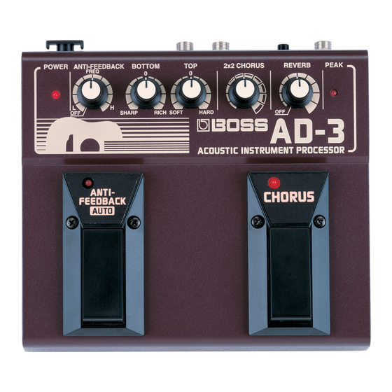
LOCATION OF CONTROLS ................................................ ...............................................................................................
HOW TO ASSEMBLE THE PAD A, B .................................. ...............................................................................................
EXPLODED VIEW ............................................................... ...............................................................................................
PARTS LIST ......................................................................... ...............................................................................................
AD-3 Test mode and version checking procedure ............... ...............................................................................................
BLOCK DIAGRAM ............................................................... ...............................................................................................
CIRCUIT DIAGRAM (MAIN) ................................................ ...............................................................................................
CIRCUIT BOARD (JACK, MAIN) ......................................... ...............................................................................................
CIRCUIT DIAGRAM (JACK) ................................................ ............................................................................................... 10
All rights reserved. No part of this publication may be reproduced in any form without the written permission of ROLAND CORPORATION.
本書の一部、もくしは全部を無断で複写・転載することを禁じます。
17059947
Dec. 1998
SERVICE NOTES
First Edition
Issued by RJA
目次
主な仕様
分解図
基板図 (JACK, MAIN)
回路図 (JACK)
Printed in Japan (AA00) (DP) 1
SPECIFICATIONS
AD-3: ACOUSTIC INSTRUMENT PROCESSOR
AD Conversion
20 bit ∆∑ Method
DA Conversion
20 bit ∆∑ Method
Sample Rate
44.1 kHz
Nominal Input Level
-10 dBm
Input Impedance
4.7 MΩ
Nominal Output Level
Page
OUTPUT: -10 dBm
OUTPUT (balanced): -10 dBm into 600 Ω
1
2
Output Impedance
OUTPUT: 300 Ω
2
OUTPUT (balanced): 600 Ω
3
Controls
4
INPUT LEVEL Knob
5
ANTI-FEEDBACK Knob
7
BOTTOM Knob
TOP Knob
8
2 × 2 CHORUS Knob
9
REVERB Knob
OUTPUT SELECT Switch
ANTI-FEEDBACK AUTO Pedal
CHORUS Pedal
POWER Switch
Indicators
ANTI-FEEDBACK AUTO
CHORUS
POWER
PEAK
Connectors
INPUT Jack
OUTPUT Jacks (L/R 1/4 inch TRS Phone Type)
AC Adaptor Jack
Power Supply
Dry battery (LR6 (AA) type) × 6
DC 9 V (PSA-Series; sold separately)
Current Draw
90 mA
Expected battery life under continuous use:
Alkaline: Approx. 17 hours
Carbon: Approx. 9 hours
These figures will vary depending on the actual conditions of use.
Dimensions
170 (W) × 156 (D) × 70 (H) mm
6-3/4 (W) × 6-3/16 (D)× 2-13/16 (H) inches
Weight
1.0 kg (including batteries)
2 lbs 4 oz
Accessories
Dry battery (LR6 (AA) type) × 6 (********)
Owner's Manual (G6017439)
Information (********)
Options
AC Adaptor PSA-Series
(0 dBm = 0.775 V rms)
Dec. 1998
主な仕様
AD-3:アコースティック・インストゥルメント・プロセッサー
● AD変換
△Σ方式20bit ADC
● DA変換
△Σ方式20bit DAC
● サンプリング周波数
44.1 kHz
● 規定入力レベル
INPUT:-10 dBm
● 入力インピーダンス
INPUT:4.7 MΩ
● 規定出力レベル
OUTPUT:-10 dBm
OUTPUT(バランス時):-10 dBm
(600 Ω負荷時)
● 出力インピーダンス
OUTPUT:300 Ω
OUTPUT(バランス時):600 Ω
● コントロール
インプット・レベルつまみ
アンチ・フィードバックつまみ
ボトムつまみ
トップつまみ
2×2コーラスつまみ
リバーブつまみ
アウトプット・セレクト・スイッチ
アンチ ・フィードバック・オート・ペダル
コーラス・ペダル
パワー・スイッチ
● インジケーター
アンチ・フィードバック・オート
コーラス
パワー
ピーク
● 接続端子
インプット・ジャック
アウトプット・ジャックL/R(TRS標準)
ACアダプター・ジャック
● 電源
単三電池×6
DC 9V(PSAアダプター:別売)
● 消費電流
90 mA
連続使用時の電池の寿命
(使用状態によって異なります)
アルカリ電池 約17時間
マンガン電池 約9時間
● 外菰寸法
170(幅)×156(奥行)×70(高さ)mm
● 重量
1.0 kg(乾電池を含む)
● 付属品
単三電池6本(********)
取扱説明書(和文G6017438)(英文G6017439)
サービスの窓口(********)
愛用者カード(********)
保証書(********)
● 別売品
ACアダプターPSA-100
0 dBm = 0.775 Vrms
1
Advertisement
Table of Contents

Related Manuals for Roland Boss AD-3


Summary of Contents for Roland Boss AD-3
-
Page 1: Table Of Contents
保証書(********) Options ● 別売品 AC Adaptor PSA-Series ACアダプターPSA-100 All rights reserved. No part of this publication may be reproduced in any form without the written permission of ROLAND CORPORATION. 0 dBm = 0.775 Vrms (0 dBm = 0.775 V rms) 本書の一部、もくしは全部を無断で複写・転載することを禁じます。 17059947 Printed in Japan (AA00) (DP) 1... -
Page 2: Location Of Controls
AD-3 Dec. 1998 /パネル配置図 / PAD A, B組立手順 LOCATION OF CONTROLS HOW TO ASSEMBLE THE PAD A, B Pot. RK11K1140 50KB (01569634) Dry Battery Pot. Knob (LR6 x 2)x 3 RK11K1140 50KB C.C UR-KNOB MF270 BLK/IVO (01569645) (01569678) Knob UR-KNOB MF270 BLK/IVO LED (Red) (01569678) The position of Battery view (toward to S-side) L-34HDSL... - Page 3 AD-3 Dec. 1998 10 11 12 13 14 15 16 17 18 19 20 21 22 23 24 25 26 27 28 29 30 31 32 33 34 35 36 37 38 39 EXPLODED VIEW /分解図 BATTERY COVER 5-U R-KNOB MF270 BLK/IVO G2027602 01569678 PEDAL LABEL ANTI-FEEDBACK AUTO...
-
Page 4: Parts List
AD-3 AD-3 Dec. 1998 Dec. 1998 /パーツリスト PARTS LIST DIODE /ダイオード、発行ダイオード 15339119T0 1SS352-TPH3 DIODE(Chip) D3 on MB F5339136 SB07-03C Schottky DIODE(Chip) D4 on MB SAFETY PRECAUTIONS: CONSIDERATIONS ON PARTS ORDERING F5339301 MTZ5.6C Zener DIODE(Tape) D1 on MB The parts marked have safety- When ordering any parts listen in the parts list, please specify the following items in the order sheet. -
Page 5: Test Mode And Version Checking Procedure
AD-3 Dec. 1998 Entering test mode ◆テスト・モードへの入り方 AD-3 Test mode and version checking procedure テストモード、バージョンの確認方法 ・まずINPUT LEVELは最大、他の全ツマミを最小にします。 • First set the INPUT LEVEL to maximum, and all other knobs to minimum. ・ANTI-FEEDBACK AUTO(以後AFB)、CHORUS(以後 • While pressing the ANTI-FEEDBACK AUTO (subsequently CHO)のPEDALを 押しながら電源を入れ、直ちに、SELECT Test items referred to as AFB) and CHORUS (subsequently referred to as CHO) スイッチを切り替えます。... - Page 6 AD-3 Dec. 1998 4. Volume check (except for INPUT LEVEL) 4. ボリュームチェック(INPUT LEVELを除く) ・まず、ノイズ・メーターをJIS-Aに切り替えて、ノイズ・レベ • First, switch the noise meter to JIS-A, and verify that the noise level • Press the AFB pedal, and the three LEDs AFB, CHO and PEAK will ・AFB PEDALを押すと、AFB、CHO、PEAKの3つのLEDが点 is less than -86 dBm.
-
Page 7: Block Diagram
AD-3 Dec. 1998 10 11 12 13 14 15 16 17 18 11. PEAK LED、INPUT LEVELボリューム チェック 11. Peak LED, Input Level volume check /ブロック図 BLOCK DIAGRAM • Turn down the LEVEL knob to the MIN position, and verify that the ・ LEVELボリュームをMIN側に絞り、出力が0dBm±1dBで PEAK LEDが消えることを確認する。 output is 0 dBm +/-1 dB, and that the PEAK LED is dark. •... -
Page 8: Circuit Diagram (Main)
AD-3 Dec. 1998 10 11 12 13 14 15 16 17 18 19 20 21 22 23 24 25 26 27 28 29 30 31 32 33 34 35 36 37 38 39 CIRCUIT DIAGRAM (MAIN)/回路図 (MAIN) 0.0022 C118 10/16 C101 C107 C109 MODE 47/16... - Page 9 AD-3 Dec. 1998 10 11 12 13 14 15 16 17 18 19 20 21 22 23 24 25 26 27 28 29 30 31 32 33 34 35 36 37 38 39 /基板図 (JACK, MAIN) CIRCUIT BOARD (JACK, MAIN) View from components side. View from components side.
-
Page 10: Circuit Diagram (Jack)
AD-3 Dec. 1998 10 11 12 13 14 15 16 17 18 19 20 21 22 23 24 25 26 27 28 29 30 31 32 33 34 35 36 37 38 39 /回路図 (JACK) CIRCUIT DIAGRAM (JACK) LEVEL OUTPUT L/LINE(MONO) 250kD 47/50 47/50 4.7k...
Need help?
Do you have a question about the Boss AD-3 and is the answer not in the manual?
Questions and answers