Advertisement
Quick Links
Advertisement
Chapters

Related Manuals for Koyo Kostac SJ-Ether Series


Summary of Contents for Koyo Kostac SJ-Ether Series
- Page 1 English version of the KOSTAC SJ-Ether series user's manual SJ- ETHER-USER-M...
- Page 2 Electric controller Symbols The symbols used in this manual are as follows. Warnin Indicates ignoring this indication may lead to serious accidents that could result in death or serious injury. Note Indicates ignoring this indication may lead to injury or property damage. Indicates general prohibition.
- Page 3 Safety instructions Be sure to observe the following safety precautions when handling products listed in this manual. [Operating Environment] Warning Do not use in an atmosphere that is flammable or explosive. Doing so may result in personal injury or fire. Do not use this product for human safety.
- Page 4 [How to use] Warning Do not touch the terminals while the power is turned on. Failure to heed this warning may result in electric shock or malfunction. Do not use the product in a manner other than those specified in the specifications. Otherwise, personal injury or failure may result.
- Page 5 Manual revision history For inquiries about this manual, please contact us with this revision number. Product name: Japanese version of the KOSTAC SJ-Ether Series User's Manual Model No.: SJ-ETHER-USER-M Version/revision Date Detail of revision First edition 2017 / 10 First edition...
- Page 6 ・ Port specification when MWX/MRX instruction is used Port3 ・ Port specification when using the EWX/ERX command Method of Addition Overall review (please: Go to) ⇒ Overall review (watchdog watchdog) For P.1-2-1-2 ・ Addition of function list by model number Properties of Functional Memory in P.2-12 2-4-2 ・...
- Page 7 Details ・ Additional explanation of the Port2 P.312-319 Appendix C SJ-Ether New Addition Order ・ Addition of explanation...
- Page 8 In addition, we cannot be responsible for the problems of industrial property rights arising from the use of the contents of this manual. The ownership of some system software of the product and software of peripheral devices belongs to Koyo Electronics Industries Co., Ltd. Others are licensed by copyrighters. It is prohibited to read, analyze, copy and publicize the contents of...
- Page 9 (4) Please be advised that we will not be responsible for the impact of the investment results regardless of the results in (3). Support Desk ・ Technical inquiries Acceptance time: 9:00 to 17:00 (excluding Saturdays, Sundays, and public holidays) (Koyo Electronics Industries Co., Ltd.) Home page For technical inquiries, Fax:...
- Page 10 About the Manual Configuration of related manuals In addition to this manual, the following related materials can also be downloaded from the website. Please use it together. Type Manual name Instruction word KOSTAC S series programming manuals Symbols If the left margin of each page is marked with a "Notepad", the contents of the paragraph immediately to the right are special notes.
-
Page 11: Table Of Contents
Contents Chapter 1 Summary ..............................1-1 Systems specification Chapter 2 ..........................2-1 Specification of each module ........................3-1 Chapter 3 Specificion of communication ........................ 4-1 Chapter 4 Chapter 5 PID Control ............................... 5-1 Chapter 6 System design ............................6-1 Maintainance Chapter 7 ............................ - Page 15 1章 章 章 章 Summary CHAPTER 1 Summary 1-1 Introduction 1-1-1 Accessory ..............................1-2 1-1-2 For use ..............................1-2 1-1-3 Application .............................. 1-4 1-1-4 Feature ..............................1-5 Systems configuration ............................1-8 Peripherals layout..............................1-9 Linking system ..............................1-10 1-4-1 Upper link .............................. 1-10...
-
Page 16: Chapter 1 Summary
Before using this product, be sure to use products with the programming software, KPP Ver. 1.6.1.2 or later. The following peripheral devices are available with this product. Graphical Programmer, etc. Acceptability KPP (Koyo PLC Programming SOFT) ○ DirectSOFT4 × DirectSOFT5.1J ×... -
Page 17: Feature
Chapter 1 Summary Some of the functions that can be used for this product model number are as follows. SJ-**DD1E-D SJ-**DD1EP-D Feature SJ-**DD2E-D SJ-**DD2EP-D SJ-**DRE-D SJ-**DREP-D High speed counter/pulse output × ○ EtherNet/IP × ○ CC-Link IEF Basic ○ × ○:Enabled/disabled... - Page 18 Chapter 1 Summary 1-1-3 Application The PLCs of the SJ-Ether series can be used for the following applications. ① Machine-control SJ-12DD1E-D K O S T A C Koyo TREM PORT3 LNK/ACT ETHER 100MBIT AD1V PORT1 AD1I AD2V AD2I RS-232C ACOM...
- Page 19 The CPU and extended I/O suitable for the system with the module structure can be selected and arranged. The terminal block of the CPU and expansion I/O module can be detached. SJ-12DD1E-D K O STAC Koyo I I I I N N N N TREM...
- Page 20 R7767 K30 Operation buzzer ●毎日、8時30分に始業ブザーを鳴らします。 It rings the starting buzzer at 8:30 everyday. ⑤ All CPUs contain two serial communication ports and one EtherNet communication port. SJ-12DD1E-D K O S T A C Koyo TREM PORT3 LNK/ACT ETHER 100MBIT AD1V...
- Page 21 Chapter 1 Summary ⑦ Have a built-in PID arithmetic function SJ-12DD1E-D K O S T A C Koyo TREM PORT3 LNK/ACT ETHER 100MBIT AD1V PORT1 AD1I AD2V AD2I RS-232C ACOM RS-485 DA1V PORT2 + DA1I ー DA2V DA2I Converter 変換器...
-
Page 22: 1-2 Systems Configuration
Maximum System Configuration: Power Module + CPU Module + 8 Extended I/O Module Power supply module CPU module Extended I/O module SJ-12DD1E-D K O ST A C Koyo I I I I N N N N TREM O O O O PORT3... -
Page 23: 1-3 Peripherals Layout
1 0 1 1 1 2 1 3 1 4 1 5 1 6 1 7 × T X 1 0 B A S E × T N .C - SJ-12DD1E-D N . C - KOSTAC 他社 PLC Other company’s PLC Koyo GC-Aシリ ーズ Series Programmer connection cable プログラマ接続ケーブル 操作表示パネル:S-10D Operation display panel :Z-20JP TREM プログラマ接続ケーブル... -
Page 24: 1-4 Linking System
SJ -12 DD 1E-D SJ -12 DD 1E-D SJ -12 DD 1E-D K O S T A C K O S T A C K O S T A C Koyo Koyo Koyo TREM TREM TREM PORT3 PORT3... - Page 25 Chapter 1 Summary Upper PLC Link System (CCM Master Function) Purpose Transfer and collection of production control information to slave PLC by master PLC, and maintenance and management of slave PLC by master PLC Feature Writing from master PLC to slave PLC and reading from slave PLC to master PLC Target memory The timing and error status of communication, such as function memory, program memory, and CPU operation mode, are defined in special relay (SP).
- Page 26 Chapter 1 Summary Non-procedure serial communication function By connecting a terminal (such as a magnetic card reader, bar code reader, printer, terminal, etc.) with serial communication interface specifications to the programmer port or general purpose communication port of the CPU module, communication can be performed without using the CCM protocol.
-
Page 27: Chapter 2 Systems Specification
2章 章 章 章 Systems specification Systems specification CHAPTER 2 In this chapter, the followings are described. General Specifications ............................2-3 Function/Performance/Specification ......................... 2-4 I/O configuration ..............................2-7 Function memory ..............................2-9 2-4-1 Function memory list ..........................2-9 2-4-2 Nature of f unction memory ........................ - Page 28 Chapter 2 Systems specification 2-12-7 Data processing command 2 ........................ 2-49 Data processing command 3 2-12-8 ........................ 2-52 2-12-9 Special command for modules ......................2-54 Drun / Ethernet communication command 2-12-10 ..................2-54 2-12-11 IBox command ........................... 2-55 List of components 2-13 ............................
-
Page 29: Systems Specification Chapter
Chapter 2 Systems specification 2-1 General Specifications I t e m Specification Rated supply voltage DC 24 V ~ Power supply voltage variation range DC 20 28 V Power consumption 5 W or less (when no power is supplied to communication port) Power inrush current 30 A or less (1 ms or less) Allowable instantaneous stopping time... -
Page 30: 2-2 Function/Performance/Specification
Chapter 2 Systems specification 2-2 Function/Performance/Specification Specification I t e m Basic Analog Control system Stored Program Cyclic Processing Method I/O control system Combined transfer method and direct input/output method Language specification Relay symbol stage combination method Command: 272 Number of instructions IBox order: 39 types Sequence instruction: 0.1us ~ Sequence instruction: 0.1 µs or less... - Page 31 Chapter 2 Systems specification Specification I t e m Basic Analog ・ I/O array check ・ Program memory check Diagnostic function ・ Operation monitoring timer (software) ・ Communication error (programmer port, general purpose communication port)
- Page 32 Chapter 2 Systems specification Specification I t e m Basic Analog Transmission method: RS-232C compliant (non-insulated) Transmission speed : 2400,4800,9600,19200,38400 bps Communication (Until 38400 bps) function :Port1 Connection: 6-pin modular (female) Programmer port Protocols: DirectNET (M/S), MODBUS (M/S), non-procedural (M/S), and K sequences (S) M-Net (M/S) Transmission method: RS-485 compliant (non-insulated) Communication...
-
Page 33: 2-3 I/O Configuration
The slot number is 0 for the CPU module, 1 for the extended I/O module next to the CPU module. The number of the module increases from the left to the right. 電源 CPU ( 0 ) Power supply SJ-12DD1E-D KOSTAC Koyo I I I I N N N N TREM O O O O PORT3 U U U U... - Page 34 Chapter 2 Systems specification I/O Array Registration and Array Checking Connect the extended I/O module to the SJ Ether PLC. When the power is turned on, the extended I/O module reads the identification code of all modules in the order of slot number. This code can be registered in the parameter area and the peripheral device can set whether to perform a comparison check.
-
Page 35: 2-4 Function Memory
Chapter 2 Systems specification 2-4 Function memory Functional memory is a memory that stores the ON/OFF state and numeric data used in user programs. Functional memory numbers (octal numbers) are separated by initial characters called identification symbols. 2-4-1 Function memory list The following table lists the functional memories that can be used in SJ Ether series and their ranges. -
Page 36: Nature Of F Unction Memory
Chapter 2 Systems specification 2-4-2 Nature of the function memory (1) Input I Functional memory I is a memory that stores the ON/OFF status (input status) of the input device connected to the input module. 入力ステータス 入力モジュール 入力機器 Input device Input module Input status (ON/OFF状態)メモリ... - Page 37 Chapter 2 Systems specification (3) Internal relay M Functional memory M is a status memory for storing the execution results of user programs and using them for internal processing. ① Relay (auxiliary relay) used only for logical operations inside the CPU. ②...
- Page 38 Chapter 2 Systems specification (6) Counter C Function memory C is a status memory which stores that the counting value exceeds the set value. (Count up status). Mnemonic Ladder ① The program execution result of the counter is stored. ② Counter counts are stored in the register corresponding to the counter number (elapsed value register). 、...
- Page 39 Chapter 2 Systems specification (9) Remote input GI Functional memory GI is used primarily to control remote I/O, but it can be used as a normal internal relay when there is no remote I/O on the system. ① The input status of the input module allocated for link input among the input modules is stored for each I/O scan. ②...
-
Page 40: Table Of Special Relay
Chapter 2 Systems specification 2-4-3 Table of special relays A special relay (SP 0 through 177) is a relay area whose application is defined in the system. User programs can only be used as contacts. Number N a m e C o n t e n t s Detailed SP000... - Page 41 Chapter 2 Systems specification Number N a m e C o n t e n t s Detailed 0:No abnormality SP040 Severe error relay ON when severe error occurs 1:Error present 0:No abnormality SP041 Slight abnormal relay ON when a slight error occurs 1:Error present 0:No abnormality SP043...
- Page 42 Chapter 2 Systems specification Number N a m e C o n t e n t s Detailed 0:When the calculation result is positive Displays the status of the most significant SP070 Sign flag 1:When the calculation result is bit (bit 31) of the ACC. negative ON when the register number of the 0:When indirect setting is normal...
- Page 43 Chapter 2 Systems specification Number N a m e C o n t e n t s Detailed Transmission condition when sending by 0:Other than during forwarding SP116 Port 2 communication flag general purpose communication port 1:During transmission (Port2) Master instruction on general purpose Port 2 communication error 0:No forwarding error SP117...
- Page 44 Chapter 2 Systems specification Number N a m e C o n t e n t s Detailed When the other party's address is the General purpose 1:IP address duplication same as the other party's address when SP206 communication port 3 0:Normal the ARP Packet is received, it is judged Duplicated IP error...
- Page 45 Chapter 2 Systems specification Number N a m e C o n t e n t s Detailed The information is updated only while you are participating in the network. This field is set to the operation status of the 0: Master station application is main function of the master station.
- Page 46 Chapter 2 Systems specification Number N a m e C o n t e n t s Detailed 0:Function not used or pulse output function initialization is ON when an initialization error Shaft 1 initialization error SP310 normal. occurs in the pulse output function relay 1:Function initialization error is shaft setting command.
- Page 47 Chapter 2 Systems specification Number N a m e C o n t e n t s Detailed SP346 Contract SP777 2-21...
-
Page 48: Special Register
Chapter 2 Systems specification 2-4-4 Special register Number N a m e C o n t e n t s Initial value R400 Data register Data register None R747 Programmer communication port (Port1) R750 Setting completed code No-procedure serial communication: Set [A55A] when setting is completed. - Page 49 Chapter 2 Systems specification Number N a m e C o n t e n t s Initial value R7421 I1 soft filter time I1 Software filter time setting (BCD: 1-99) ms R7422 I2 soft filter time I2 Software filter time setting (BCD: 1-99) ms R7423 I3 soft filter time I3 Software filter time setting (BCD: 1-99) ms...
- Page 50 Chapter 2 Systems specification Number N a m e C o n t e n t s Initial value Setting range 1 to 9999 ms (BCD), 0: Interrupt not Ch3 timer interrupt R7616 used Setting time Interrupt number: ILBL O12 Setting range 1 to 9999 ms (BCD), 0: Interrupt not Ch4 timer interrupt R7617...
- Page 51 Chapter 2 Systems specification Number N a m e C o n t e n t s Initial value General purpose Example 192.168.0.10 (stored on BCD) R7660-R7663 communication port 3 192.168.0.10 R7660=192 R7661=168 R7662=0 R7663=10 IP address General purpose 255.255.0.0 (stored on BCD) R7664-R7667 communication port 3 255.255.0.0...
- Page 52 Chapter 2 Systems specification Number N a m e C o n t e n t s Initial value Counter setting value start R7721 S-10D: Counter setting register top number None register number R7722 Timer counter points S-10D: Number of timers/counters set None R7723-R7725 Prohibition of use...
- Page 53 Chapter 2 Systems specification Number N a m e C o n t e n t s Initial value CC-Link IEF Basic The information is updated only while you are None R7737 Master station participating in the network. ~ Calendar (year) 00 99[BCD] Setting up the communication auto reset timer of the 3030...
-
Page 54: Application Specified Internal Relay
Chapter 2 Systems specification 2-4-5 Application specified internal relay The following areas are internal relay areas, but they are used for remote I/O setup that is connected to some general purpose communication ports (Port2). Number N a m e C o n t e n t s Initial value Remote I/O After writing to the remote I/O setup table, the ladder... -
Page 55: 2-5 User Memory
Chapter 2 Systems specification 2-5 User memory User's Memory includes program memory for programming PLC operations and system parameters for defining the system. 2-5-1 Configuration of user's memory ... In the user program area, subroutines and interrupt routines are Programming memory 7.5K also programmed into this area ... -
Page 56: List Of System Parametaers
Chapter 2 Systems specification 2-5-3 List of System Parameters System parameters are used to define the system. System parameter ・ Alphanumeric characters within 8 digits in the name of the user Program-name program ・ 8 digits of the program's security code Passwords ・... - Page 57 Chapter 2 Systems specification CAUTION: Retention of the timer/counter elapsed value register follows the setting of the power failure holding area of the timer/counter. If the system parameters are changed from peripheral tools to the PLC in RUN mode, set the system parameters to STOP mode once.
-
Page 58: Separate Description Of System Parameter
Chapter 2 Systems specification 2-5-4 Separate description of system parameter Program-name This area registers the name for program identification. Passwords Setting the password limits the functions that can be operated. There are two types, normal and restricted. ① Normal password You register the password with an 8-digit number (BCD). -
Page 59: 2-6 Scan And I/O Transfer
Chapter 2 Systems specification 2-6 Scan and I/O transfer 2-6-1 CPU execution process When the sequence when the power is turned on is finished, the SJ Ether series CPU repeatedly executes the I/O transfer program as a normal scan. 電源投入 The power is on ハードウエアの初期化... -
Page 60: Scanning
Chapter 2 Systems specification 2-6-2 Scanning When the CPU operation mode is RUN, the user program executes operations from the start address to the last address. In addition to executing programs, CPUs perform processing (I/O transfer) for reading and writing I/O status, communication services, module services, and other services. -
Page 61: 2-7 Self-Diagnosis Function
Chapter 2 Systems specification 2-7 Self-diagnosis function The SJ Ether series CPU checks each scan to see if it is working properly. If an error is detected, the LED and special relay on the CPU surface panel are turned on and the error code is stored in the special register. Stops scanning for fatal errors. Error Detection Abnormality... - Page 62 Chapter 2 Systems specification Error Detection Abnormality Error code Contents of detection ERR LED Timing operation Relay register Coding I/O bus error Flashing At all times Suspension SP45 R7755 Failure of I/O bus or I/O bus connecting equipment. (I/O bus check: once a scan) Causal factors Extended I/O modules are mounted more than the maximum number of modules mounted 8 modules.
-
Page 63: 2-8 Cpu Operation Mode
Chapter 2 Systems specification 2-8 CPU operation mode In the operation mode of the CPU, you can select the forced RUN and TERM mode using the mode switching switch. In TERM mode, you can switch from KPP to RUN, TEST RUN, TEST-STOP, and STOP modes. 2-8-1 CPU operation mode and contents CPU operation mode... -
Page 64: Changing The Cpu Operation Mode
Chapter 2 Systems specification 2-8-3 Changing the CPU operation mode The operation to switch from RUN mode to TEST mode is performed by KPP. Click the PLC mode button on the online toolbar, select PLC>PLC mode switching on the main menu, or use the keyboard shortcut key Ctrl+Shift +R. The PLC mode window is displayed as shown below. -
Page 65: 2-9 Debugging Facility
Chapter 2 Systems specification 2-9 Debugging facility The debugging function is used to detect program failures (bugs). Use the debugging function of KPP. 2-9-1 Functions of TEST-STOP modes (1) Start of PLC scan Set PLC to TEST RUN mode and execute PLC scanning. Continue scanning until the PLC scan stop button is pressed. (2) PLC scan stop Sets the PLC to TEST-STOP mode and stops scanning the PLC. -
Page 66: 2-10 Battery On/Off Setting
Chapter 2 Systems specification 2-10 Battery ON/OFF setting In the SJ Ether series, a lithium battery (commercially available CR2354) can be used to hold the content of the system RAM storage memory even if it is not connected to an external power source. Refer to 7-3 Battery Installation/Replacement Method for how to mount/replace the battery. -
Page 67: 2-11 History Information Storage Function
Chapter 2 Systems specification 2-11 History information storage function The history information storage function stores a self-diagnosis error detected by the CPU. You can display error information and messages that have occurred in the past on the KPP or the operation display panel S-10D. Even if the operator is not constantly monitoring, it is possible to inspect occasional errors later and is useful for maintenance. -
Page 68: 2-12 List Of Command Words
Chapter 2 Systems specification 2-12 List of command words 2-12-1 Command word and operand Command word Example 例 命令語 タイプ1 Type 1 Command 命令 ANDLD タイプ2 Type 2 Command Operand 命令 I000 オペランド Command Operand Operand オペランド タイプ3 オペランド 命令 LDGE R2000 K1234... -
Page 69: Sequence Command 2
Chapter 2 Systems specification 2-12-2 Sequence command 1. Number Classification Order Operand of words Logical operation start NO contact Logical operation start NC contact Contact Logical integration NO contact 、 、 、 、 、 、 、 GI GQ I Q M S T C instruction Logical Accumulation NC Contact ANDN... - Page 70 Chapter 2 Systems specification 2-12-3 Sequence command 2. Classification Order Operand word Coil-on operation (OR operation) Coil-on operation (after priority) ZOUT I,Q,M Coil-on operation Output ZOUTH (Override status ignored) command Coil set operation I, Q, M, S for the 1st and 2nd words NOTE)For the function number of the first/second word Coil reset operation...
- Page 71 Chapter 2 Systems specification Note: *1: Use an even number to use two words as the elapsed value of the timer (counter). *The last register in each register range cannot be specified because 2:2 word register is used. *3:Duplicate use of ZOUT, PD, and SET/RST commands for the same coil is prohibited. The coils used in interrupt processing cannot be used in other interrupt processing or normal processing.
-
Page 72: Program Execution Control Command
Chapter 2 Systems specification 2-12-4 Program execution control command Classification Order Operand word Stage Registration Order Initial Stage Registration Order Command for transition to condition fulfillment stage Stage Impossible Stage Transition Command NJMP Type Confluence stage registration instruction instruction Confluent stage transfer instruction CVJMP Stage block movement instruction BREQ... -
Page 73: Data Processing Command
Chapter 2 Systems specification 2-12-5 Data processing command 1. Classification Order Operand word R Entire register range 16 bits P Entire range of indirect registers R Register total range *1 32 bits P Entire range of indirect registers GI,GQ,I, Q, M, S, T, C, SP Arbitrary-bit K Bits 1 to 32 Direct 16 bits... -
Page 74: Ascii Command
Chapter 2 Systems specification Note: *1:2 word register, so it is recommended to specify an even number. Also, the last register in the register range cannot be specified. *2:Special relay area cannot be specified. Classification Order Operand word R Register total range *1 Four digits P Entire range of indirect registers R Register total range *1 *2... -
Page 75: Data Processing Command 3
Chapter 2 Systems specification 2-12-7 Data processing command 2. Classification Order Operand word R Entire register range 16 bits BADD *3 P Entire range of indirect registers R Register total range *1 32 bits BADDD BIN addition P Entire range of indirect registers Stacked SBADD No operand... - Page 76 Chapter 2 Systems specification Classification Order Operand word 1st word: GI, GQ, I, Q, M, S, T, C, SP Arbitrary bit length (1 to 32) ANDF 2nd word: K 1-32 Stacked SAND No operand ~ 8-digit constant ANDC K 0 FFFFFFFF R Entire register range 16 bits P Entire range of indirect registers...
- Page 77 Chapter 2 Systems specification Classification Order Operand R Entire register range 16 bits XORW P Entire range of indirect registers R Register total range *1 32 bits XORD P Entire range of indirect registers Exclusive Logical-su 1st word: GI, GQ, I, Q, M, S, T, C, Arbitrary bit length (1 to 32) XORF 2nd word: K 1-32...
- Page 78 Chapter 2 Systems specification 2-12-8 Data processing command 3. Numb Classification Order er of Operand words R Entire register range 16 bits CMPR P Entire range of indirect registers R Register total range *1 32 bits CMPRD P Entire range of indirect registers Compare 、...
- Page 79 Chapter 2 Systems specification Numb Classification Order er of Operand words BCD increment INCR Register BCD decrement DECR R Entire register range Conversion BIN increment BINC P Entire range of indirect registers command BIN decrement BDEC R Entire register range Transferred MOVE P Entire range of indirect registers...
-
Page 80: Special Command For Modules
Chapter 2 Systems specification 2-12-9 Special command for modules Numb Classification Order er of Operand words GI, GQ, I, Q, M, S, T, C Reading the data Telecommunicati SP, R, L, X GI, GQ, I, Q, M, S, T, C Module Writing of data SP, R, L, X... -
Page 81: Ibox Command
Chapter 2 Systems specification 2-12-11 IBox command Number Classification Order Operand of words Commencement of IBOX Completion of the IBOX 16-bit copy MOVEW Memory 32-bit copy MOVED OFF delay timer OFFDTMR ON delay timer ONDTMR Discrete 1 scan output ONESHOT Toggle-switch PONOFF High/Low Alarm Binary... -
Page 82: 2-13 List Of Components
Chapter 2 Systems specification 2-13 List of Components 2-13-1 Part number naming method CPU module Series シリーズ記号 symbol 種別 Type 11: Basic 11:ベーシック Output type of DC 12:アナログ DC出力形式 12: Analog 1: Sink output 2:Source output 1:シンク出力、2:ソース出力 Type of output 出力の種別... - Page 83 Chapter 2 Systems specification Current and voltage mixing modules Series symbol シリーズ記号 Module type モジュールタイプ 1: Electric current type Number of points 1:電流タイプ 2:電圧タイプ 2: Voltage type 点数 Indicates the number of I/O 外部に提供されるI/O点数を Type of I/O 入出力の種別 points to be provided to 数字で表す...
-
Page 84: List Of Components
Chapter 2 Systems specification 2-13-2 List of Components Classifi N a m e Model number Feature Weight Remarks cation SJ-11DD1E-D 140 g SJ-11DD2E-D 140 g SJ-11DRE-D 160 g Basic SJ-11DD1EP-D 140 g SJ-11DD2EP-D 140 g SJ-11DREP-D 160 g CPU module SJ-12DD1E-D 150 g SJ-12DD2E-D... - Page 85 Chapter 2 Systems specification Classifi N a m e Model number Feature Weight Remarks cation 16 bit resolution On/off-line programming, monitor and PC programmer printout Change of monitor and T/C setting Operation display panel S-10D 160 g Message display Project Editing, Monitor, Change of Simplified programmer S-20P 220 g...
-
Page 86: Dimentional Outline Drawing
Chapter 2 Systems specification 2-14 Dimensional outline drawing [ S J E t h e r U p p e r ] Unit (mm) [ S J - E t h e r F r o n t ] M4用取付穴 Attachment hole for M4 Attachment hole for M4 M4用取付穴... - Page 87 Chapter 2 Systems specification Number of extended I/O module 拡張IOモジュール数 115.4 142.4 169.4 196.4 223.4 250.4 277.4 304.4 [Ether Aspects] Unit (mm) 2-61...
- Page 90 3章 Module specific specifications CHAPTER 3 In this chapter, those written below is described CPU module ................................. 3-3 3-1-1 List of models ............................3-3 3-1-2 Main power supply specification ......................3-3 3-1-3 Common hardware specification ......................3-3 3-1-4 I/O Function Specification with Built-in SJ-11DD1E-D/...
- Page 91 Built-in analog data input/output function .................... 3-58 3-6-1 Operation of the built-in module ......................3-58 3-6-2 Analog data input/output register with built-in CPU ................3-59 3-6-3 Register setting for analog data with built-in CPU ................3-60 3-6-4 Register for setting optional analog module ..................
-
Page 92: Cpu Module
CPU module The CPU modules of the SJ Ether series are equipped with discrete I/O and analog I/O (analog type) and have a total of six models. Individual specifications are as follows. 3-1-1 List of Models Model number Discrete Analog T y p e SJ-***E-D SJ-***EP-D... - Page 93 Mode-switch This is the slide switch for selecting the operation mode of the PLC. This is the two positions of the RUN and TERM. M o d e Description The CPU is in operation (forced RUN mode). Operation of mode change (RUN/TEST/STOP) can be performed TERM by peripheral devices.
-
Page 94: I/O Function Specification With Built-In Sj-11Dd1E-D/ Sj-11Dd1Ep-D
3-1-4 I/O Function Specifications with Built-in SJ-11 DD1E D/SJ-11 DD1EP D SJ-11DD1EP-D SJ-11DD1E-D KOS T AC KOSTAC Koyo Koyo TREM TREM PORT3 PORT3 LNK/ACT LNK/ACT ETHER ETHER 100MBIT 100MBIT PORT1 PORT1 RS-232C RS-232C RS-485 RS-485 PORT2 PORT2 + + ー... - Page 95 Equivalent circuit 3.3V Internal Module circuitry INPUT Input 24VDC (I0 – I7) Capabilities Internal Module circuitry 24VDC 3.3V 5-27VDC Output (Q0-Q5) Capabilities...
-
Page 96: I/O Function Specification With Built-In Sj-11Dd2E-D/ Sj-11Dd2Ep-D
3-1-5 I/O Function Specifications with Built-in SJ-11 DD2E D/SJ-11 DD2EP D SJ-11DD2EP-D SJ-11DD2E-D KOS T AC KOS T AC Koyo Koyo TREM TREM PORT3 PORT3 LNK/ACT LNK/ACT ETHER ETHER 100MBIT 100MBIT PORT1 PORT1 RS-232C RS-232C RS-485 RS-485 PORT2 PORT2 +... - Page 97 Equivalent circuit 3.3V Internal Module circuitry INPUT 24VDC Input (I0-I7) Capabilities Internal Module circuitry 24VDC 3.3V Output (Q0-Q5) Capabilities...
-
Page 98: I/O Function Specification With Built-In Sj-11Dre-D/ Sj-11Drep-D
3-1-6 I/O Function Specifications with Built-in SJ-11DRE-D/SJ-11 DREP D SJ-11DRE-D SJ-11DREP-D KOS T AC KOS T AC Koyo Koyo TREM TREM PORT3 PORT3 LNK/ACT LNK/ACT ETHER ETHER 100MBIT 100MBIT PORT1 PORT1 RS-232C RS-232C RS-485 RS-485 PORT2 PORT2 + + ー... - Page 99 Relay life (ON→OFF 1 cycle) Loading condition Life DC 30 V, 3 A resistive 100,000 cycle loads more DC 30 V, 3 A induced 50,000 cycle loading more 100,000 cycle AC250 V, 3 A resistive load more AC250 V, 3 A inductive 20,000 cycle load...
-
Page 100: I/O Function Specification With Built-In Sj-12Dd1E-D/ Sj-12Dd1Ep-D
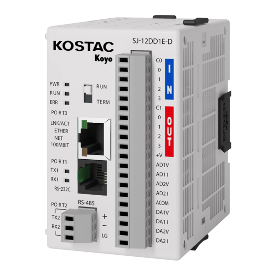
3-1-7 I/O Function Specifications with Built-in SJ-12 DD1E D/SJ-12 DD1EP D SJ-12DD1E-D SJ-12DD1EP-D KOS T AC KOS T AC Koyo Koyo TREM TREM PORT3 PORT3 LNK/ACT LNK/ACT ETHER ETHER 100MBIT 100MBIT AD1V AD1V PORT1 PORT1 AD1I AD1I AD2V AD2V AD2I... - Page 101 Equivalent circuit 3.3V Internal Module circuitry INPUT 24VDC Input (I0-I3) Capabilities Internal Module circuitry 24VDC 3.3V 5-27VDC Output (Q0-Q3) Capabilities 3-12...
- Page 102 Analogue input/output specifications Specifications of the analog input I t e m Voltage input selection Current input selection Number of inputs Up to 2 channels depending on current input and voltage input selection Input voltage range 0~ 5 V Input current range 4~...
- Page 103 Equivalent circuit Voltage input selection Current input selection Internal Module Circuitry Internal Module Circuitry ADxV 10KΩ ADxI Voltage Current Transmitter Converter Transmitter Converter 10KΩ 125Ω Transmitter Transmitter Voltage output selection Current output selection Internal Module Circuitry Internal Module Circuitry DAxI DAxV Load Load...
- Page 104 3-1-8 I/O Function Specifications with Built-in SJ-12 DD2E D/SJ-12 DD2EP D SJ-12DD2E-D SJ-12DD2EP-D KOS T AC KOS T AC Koyo Koyo TREM TREM PORT3 PORT3 LNK/ACT LNK/ACT ETHER ETHER 100MBIT 100MBIT AD1V AD1V PORT1 PORT1 AD1I AD1I AD2V AD2V AD2I...
- Page 105 Equivalent circuit 3.3V Internal Module circuitry INPUT 24VDC Input (I0-I3) Capabilities Internal Module circuitry 24VDC 3.3V Output (Q0-Q3) Capabilities 3-16...
- Page 106 Analogue input/output specifications Specifications of the analog input I t e m Voltage input selection Current input selection Number of inputs Up to 2 channels depending on current input and voltage input selection Input voltage range 0~ 5 V Input current range 4~...
- Page 107 Equivalent circuit Voltage input selection Current input selection Internal Module Circuitry Internal Module Circuitry ADxV 10KΩ ADxI Voltage Current Transmitter Converter Transmitter Converter 10KΩ 125Ω Transmitter Transmitter Voltage output selection Current output selection Internal Module Circuitry Internal Module Circuitry DAxI DAxV Load Load...
-
Page 108: I/O Function Specification With Built-In Sj-12Dre-D/ Sj-12Drep-D
3-1-9 I/O Function Specifications with Built-in SJ-12DRE-D/SJ-12 DREP D SJ-12DRE-D SJ-12DREP-D KOS T AC KOS T AC Koyo Koyo TREM TREM PORT3 PORT3 LNK/ACT LNK/ACT ETHER ETHER 100MBIT 100MBIT AD1V AD1V PORT1 PORT1 AD1I AD1I AD2V AD2V AD2I AD2I RS-232C... - Page 109 Relay life (ON→OFF 1 cycle) Loading condition Life DC 30 V, 3 A resistive 100,000 cycle loads more DC 30 V, 3 A induced 50,000 cycle loading more 100,000 cycle AC250 V, 3 A resistive load more AC250 V, 3 A inductive 20,000 cycle load...
- Page 110 Analogue input/output specifications Specifications of the analog input I t e m Voltage input selection Current input selection Number of inputs Up to 2 channels depending on current input and voltage input selection Input voltage range 0~ 5 V Input current range 4~...
- Page 111 Equivalent circuit Voltage input selection Current input selection Internal Module Circuitry Internal Module Circuitry ADxV 10KΩ ADxI Voltage Current Transmitter Converter Transmitter Converter 10KΩ 125Ω Transmitter Transmitter Voltage output selection Current output selection Internal Module Circuitry Internal Module Circuitry DAxI DAxV Load Load...
-
Page 112: Power-Supply Module
Power-supply module I t e m Specification Remarks Model number C0-01AC Power supply rating AC100~ 240 V 50/60 Hz Allowable voltage range AC85~ 264 V AC frequency 47~ 63 Hz Maximum apparent 37 VA power Inrush current 20 A (cold start) Output current DC24 V 1.3 A Weight... - Page 113 Note: Refer to 6-3-3 Module Assembly for connections and locks between modules. 3-24...
-
Page 114: Power Specification
3-2-1 Power specification Item Specification Input Voltage Range 20-28 V DC with less than 10% ripple Operating Voltage Range 24 V DC Maximum Power (only CPU) 5 W (No 5 V use from communication port) Maximum Power 20 W (Max. system: CPU + 8 I/O module) Inrush Current 30 A maximum (1ms maximum) Instantaneous Power Failure Time... -
Page 115: Extended I/O Module
Extended I/O module 3-3-1 Extended I/O Module List Actual Number of Type Model number Specification points occupied points J-08ND3 Sink-source 8 points 8 points J-08ND3-1 Sink-source DC 3.3/5 V 8 points 8 points J-16ND3 Sink-source DC 24 V 16 points 16 points J-08NA AC 100~... -
Page 116: Common Hardware Specification
3-3-2 Common hardware specifications → Front 正面 ・ PWR (Green): This lamp lights when the power is turned on. ・ I/O status (Green): Input (LED of corresponding I/O terminal lights) (Red): Output (LED of corresponding I/O terminal lights) Terminal block This is a removable European-type terminal block. -
Page 117: 8-Point Dc 12/24 V Input Module: J-08Nd3
3-3-3 8-Point DC 12/24 V Input Module: J-08ND3 You can use either DC 12 V or DC 24 V sink/source inputs. I t e m Input specification Number of inputs 8 points (sink/source) Number of occupied input points Eight points Common 2 (4 points/common) Input voltage range... -
Page 118: Dc3.3/5 V Input Module: J-08Nd3-1
3-3-4 DC3.3/5 V Input Module: J-08ND3-1 You can use either DC 3.3 V or DC 5 V sink/source inputs. I t e m Input specification Number of inputs 8 points (sink/source) Number of occupied input points Eight points Common 2 (4 points/common) Input voltage range DC 3.3/5.0 V Operating voltage range... -
Page 119: 16-Point Dc 24 V Input Module :J-16Nd3
3-3-5 16-point DC 24 V input module: J-16ND3 You can use either DC 24 V sink or source input. I t e m Input specification Number of inputs 16 points (sink/source) Number of occupied input points 16 points Common 4 (4 points/common) Input voltage range DC 24 V Operating voltage range... -
Page 120: 8-Point Ac 100-120 V Input Module: J-08Na
3-3-6 8-point AC 100-120 V input module: J-08NA I t e m Input specification Number of inputs 8 points (AC) Number of occupied input points Eight points Common 2 (4 points/common) Input voltage range AC 100~ 120 V Operating voltage range AC 80~... -
Page 121: 8-Point Output Module: J-08Td1
3-3-7 8-point output module: J-08TD1 I t e m Output specification Number of output 8 points (sink) Number of occupied output Eight points Common 2 (4 points/common) Output voltage range DC 3.3~ 27 V Operating voltage range DC 2.8~ 30 V Peak voltage DC 30 V Output type... -
Page 122: 8-Point Output Module: J-08Td2
3-3-8 8-point output module: J-08TD2 I t e m Output specification Number of output 8 points (source) Number occupied Eight points output Common 2 (4 points/common) Output voltage range DC 12/24 V Operating voltage range DC 9.6~ 30 V Peak voltage DC 30 V Output type PMOS FET... -
Page 123: 16-Point Output Module: J-16Td1
3-3-9 16-point output module: J-16TD1 I t e m Output specification Number of output 16 points (sink) Number of occupied output 16 points Common 2 (8 points/common) Output voltage range DC 5~ 27 V Operating voltage range DC 4~ 30 V Peak voltage DC 30 V Output type... -
Page 124: 16-Point Output Module: J-16Td2
3-3-10 16-point output module: J-16TD2 Item Output specification Number of output 16 points (source) Number of occupied output 16 points Common 2(8 points/common) Output voltage range DC 12/24 V Operating voltage range DC 9.6~ 30 V Peak voltage DC 30 V Output type PNP open collector Voltage drop on... -
Page 125: 8-Point Output Module: J-08Ta
3-3-11 8-point output module: J-08TA I t e m Output specification Number of output 8 points (AC) Number of occupied output Eight points Common 2 (4 points/common) Output voltage range AC 17~ 240 V Operating voltage range AC 13.5~ 288 V Peak voltage AC 288 V Output type... -
Page 126: 8-Point Relay Output Module: J-08Tr
3-3-12 8-point relay output module: J-08TR I t e m Output specification Number of output Eight points Number of occupied output Eight points Common 2 (4 points/common) Rated output voltage DC 24 V/AC 240 V Operating voltage Max. DC 30 V max. AC 264 V Output type Relay formatA (SPST)*1 AC frequency... -
Page 127: 4-Point Relay Output Module: J-04Trs
3-3-13 4-point relay output module: J-04TRS I t e m Output specification Number of output Four points Number of occupied output Eight points Common 4 (1 point/common) Rated output voltage DC 24 V/AC 240 V Operating voltage Max. DC 30 V max. AC 264 V Output type Relay format C(SPDT)*1 AC frequency... -
Page 128: 4-Point Dc Input/4-Point Relay Output Module: J-08Cdr
3-3-14 4-point DC input/4-point relay output module: J-08CDR I t e m Input specification Number of inputs Four (sink/source) Number of occupied input Eight points points Common 1 (4 points/common) Input voltage range DC 12/24V Operating voltage range DC 10.8~ 26.4V Peak voltage DC 26.4V Input current... - Page 129 I t e m Output specification Number of output Four points Number of occupied output Eight points Common 1 (4 points/common) Rated output voltage DC 24 V/AC 240 V Operating voltage Max. DC 30 V max. AC 264 V Output type Relay formatA (SPST)*1 AC frequency 47~...
-
Page 130: 8-Point Input/8-Point Output Module: J-16 Cdd1
3-3-15 8-point input/8-point output module: J-16 CDD1 I t e m Input specification Number of inputs 8 points (sink/source) Number of occupied input Eight points points Common 1 (8 points/common) Input voltage range DC 24 V Operating voltage range DC 21.6~ 26.4 V Peak voltage DC 26.4 V Input current... - Page 131 I t e m Output specification Number of output 8 points (sink) Number of occupied output Eight points Common 1 (8 points/common) Output voltage range DC 5~ 27 V Operating voltage range DC 4~ 30 V Peak voltage DC 30 V Output type NPN open collector Voltage drop on...
-
Page 132: 8-Point Input/8-Point Output Module: J-16 Cdd2
3-3-16 8-point input/8-point output module: J-16 CDD2 I t e m Input specification Number of inputs 8 points (sink/source) Number of occupied input Eight points points Common 1 (8 points/common) Input voltage range DC 24 V Operating voltage range DC 21.6~ 26.4 V Peak voltage DC 26.4 V Input current... - Page 133 I t e m Output specification Number of output 8 points (source) Number of occupied output Eight points Common 1(8 points/common) Output voltage range DC 12/24 V Operating voltage range DC 9.6~ 30 V Peak voltage DC 30 V Output type PNP open collector Voltage drop on DC 0.6 V(0.1 A)
-
Page 134: Channel Current Input Module :C0-04Ad-1
3-3-17 4 Channel Current Input Module: C0-04AD-1 C0-04AD-1 2 wiring 2線式 0-20mA 4-20mA Signal source 4-20mA 信号源 2 wiring 2線式 4-20mA Signal source 4-20mA 信号源 3線式 3 wiring 4-20mA Signal source 4-20mA 信号源 全ての0 Vは connected inside. 内部で接続さ れています。 4 wiring 4線式... -
Page 135: Channel Voltage Input Module: C0-04Ad-2
3-3-18 4 Channel voltage input module: C0-04AD-2 C0-04AD-2 電圧 Voltage 0-10 V generator 発生源 電圧 Voltage generator 発生源 電圧 Voltage generator 発生源 全ての0 Vは connected inside. 内部で接続さ れています。 電圧 Voltage generator 発生源 24 VDC 電源 Power supply C0-04AD-2 Analogue Input Specification Number of inputs Input current range 0-10 V... -
Page 136: Channel Current Output Module: C0-04Da-1
3-3-19 4 Channel Current Output Module: C0-04DA-1 C0-04DA-1 4-20 mA 全ての0 Vは 内部で接続さ connected inside. れています。 24 VDC 電源 Power supply C0-04DA-1 analogue output specification Number of output Output Current Range 4-20 mA 12 bit, 3.9 μA/counts Resolution Output-type Max. 20 mA, Source 1 Common Output value in fault mode Less than 4 mA Load-impedance... -
Page 137: Channel Voltage Output Module: C0-04Da-2
3-3-20 4 Channel Voltage Output Module: C0-04DA-2 C0-04DA-2 0-10 V 全ての0 Vは connected inside. 内部で接続さ れています。 24 VDC 電源 Power supply C0-04DA-2 analogue output specification Number of output Output voltage range 0-10 V Resolution 12 bit, 2.44 mV/counting Output-type Max. 10 V, Source 1 Common Output value in fault mode Output impedance 0.2q... -
Page 138: Channel Current Input/2 Channel Current Output Module: C0-4 Ad2Da-1
3-3-21 4 Channel Current Input/2 Channel Current Output Module: C0-4 AD2DA-1 全ての0 Vは 2 wiring 2線式 C0-4AD2DA-1 connected inside. 4-20mA Signal source 内部で接続さ 4-20mA 信号源 0-20mA IN 4-20mA Out れています。 2 wiring 2線式 N.C. 4-20mA Signal source 4-20mA 信号源 3 wiring N.C. - Page 139 C0-4 AD2DA 1 Analogue Input Specifications Number of inputs Input current range 0-20 mA 13 bit, 2.44 μA/counts Resolution Input-type Sink input, 1 common Maximum continuous overload ±44 mA 124 Ω、 0.5 W Input-impedance Filtering characteristic By Low pass. 120 Hz-3 dB Sampling time 5 ms All channel update cycles...
-
Page 140: Channel Voltage Input/2 Channel Voltage Output Module: C0-4 Ad2Da-2
3-3-22 4 Channel Voltage Input/2 Channel Voltage Output Module: C0-4 AD2DA-2 全ての0 Vは 電圧 Voltage C0-4AD2DA-2 connected inside. 内部で接続さ generator 発生源 0-10V れています。 電圧 Voltage N.C. generator 発生源 電圧 N.C. Voltage generator 発生源 N.C. 電圧 Voltage generator 発生源 N.C. N.C. N.C. - Page 141 C0-4 AD2DA 2 Analogue Input Specifications Number of inputs Input current range 0-10 V Resolution 13 bit, 1.22 mV/counting Input-type Sink input, 1 common Maximum continuous overload ± 100 VDC 150 KqΩ Input-impedance Filtering characteristic By Low pass. 150 Hz-3 dB Sampling time 6.25 ms All channel update cycles...
-
Page 142: 4 Channel Thermocouple Analog Input Module: C0-04Thm
3-3-23 4 Channel thermocouple analog input module: C0-04THM C0-04THM J,K,E,R,S,T,B,N,C,mV 全てのCOM端子は terminals 内部で接続され connected inside. シールド Shield ています。 TC1+ TC1- TC2+ TC2- Device デバイス TC3+ mV デバイス Power Device 電源 TC3- supply TC4+ TC4- mV デバイス Device C0-04THM Analogue Input Specification Number of inputs -1.3 ~... -
Page 143: Channel Tempereture Resistor Analogue Input Module : C0-04Rtd
3-3-24 4 Channel Temperature Resistor Analogue Input Module: C0-04RTD C0-04RTD Pt, Cu, Ni, RES COM端子は COM terminls are separated. 分離しています。 C0-04RTD Analogue Input Specification Number of inputs Common mode range ±2.5 V Common mode rejection 100dB DC、 130 dB 50/60 Hz Input-impedance 5 Mg or more Maximum rating... -
Page 144: Pc Programmer Kpp
PC programmer KPP For SJ-Ether series, use the PC programmer KPP to program. KPP is software for S-Series Programmable Controllers running on the Windows of a commercially available PC. (1) Primary function of KPP ・ Online program ・ Offline program ・... -
Page 145: Cabling
Cabling ① KPP, Connect Upper Computer SJ-12DD1E-D KOS T AC Peripheral connection cable Conversion connector Koyo Z-20JP S-9CNS1 TREM PORT3 LNK/ACT ETHER 100MBIT AD1V PORT1 AD1I AD2V AD2I RS-232C ACOM RS-485 DA1V PORT2 + DA1I ー DA2V DA2I Z-20JP S-9CNS1... -
Page 146: Peripheral Cable: Z-20Jp
3-5-1 Peripheral cable: Z-20JP This cable connects the CPU module and the operation display panel S-10D. It is also used in conjunction with the conversion connector to connect to KPP and non-procedure serial communication equipment. I t e m Specification Plug type A Modular 6-pin Cable length (m) -
Page 147: Operation Of The Built-In Module
Built-in analog data input/output function The SJ Ether series can use analog-type CPU modules or analog-type extended I/O modules to enable analog-data input and output. Refer to 3-1 CPU Module and 3-3 Extended I/O Module for the specifications of each module. 3-6-1 Operation of the built-in module Input: Channel Scan Sequence... -
Page 148: Analog Data Input/Output Register With Built-In Cpu
3-6-2 Analogue data input/output register with built-in CPU This register applies only to analog type CPUs. Input specification Input-type Input format Input data R7600 (bit 13) R7600 (bit 15) R7601 R7600 (bit 14) R7600 (bit 15) R7602 Output specification Output-type Output format Output data R7600 (bit 13) -
Page 149: Register Setting For Analog Data With Built-In Cpu
I/O data specifications and resolution アナログ入出力データレジスタ Analog I/O data register 12 11 ビット Data bit データビット Bits 0 to 11 of I/O data are analog data displayed in binary format. The presence of 12 bits of data means that it has a 12-bit resolution. -
Page 150: Register For Setting Optional Analog Module
3-6-4 Register for setting optional analog module When the analog module is mounted on the analogue with built-in CPU and the extended module Slot1~Slot8, the special register area shown below becomes the setting area. When the setting parameters are changed, the initialization process is performed. I/O update processing of other extension modules stops. -
Page 151: Detailed Register Information For Setting Optional Analog Module
3-6-5 Detailed register information for setting optional analog module The first register number of each Slot shall be Rn. Register number Model number C0-04AD-1、 C0-04AD-2、 C0-04THM C0-4AD2DA-1、 C0-4AD2DA-2、 C0-04RTD C0-04DA-1、 C0-04DA-2 Rn + 0 Bit15: BIN/BCD selection Bit15: BIN/BCD selection 0=BCD, 1=BIN 0=BCD, 1=BIN Bit14 : Input Error Setting... - Page 152 Converted data is stored in the first register number (Rxxx0) of the converted data stored in Rn+2 for each part number. Register C0-04AD-1 C0-04DA-1 C0-04THM C0-4AD2DA-1 C0-04RTD ※ number C0-04AD-2 C0-04DA-2 C0-4AD2DA-2 Resolution of 13 12 bit resolution 16 bit resolution AD resolution AD/13 bit、...
- Page 154 4章 Communication specification Communication specification CHAPTER 4 In this chapter, the followings are described. Chapeter4 Communication specification ..........................4-1 Communications port ............................4-2 4-1-1 Programmer port ............................4-2 4-1-2 General purpose communication port ...................... 4-5 Communication setting ............................4-12 4-2-1 K sequence .............................
-
Page 155: Communications Port
Communications port The presence or absence of SJ-Ether communication ports is as follows. General purpose Programmer port communication port Port 1 Port 2 Port 3 Module RS-232C RS-485 Ethernet ○ ○ ○ Basic ○ ○ ○ Analog For network specifications, RS-232C is suitable for simple networks such as communication between two devices with a short distance (max. - Page 156 flashing Not sent Green Receiving flashing Not received...
- Page 157 Fixed serial communication mode The protocol in fixed serial communication mode is shown below. Item Performance Remarks Signaling RS-232C compliant levels Transmission 9600 bps fixation rate Transmission Within the 10 m distance Connecting Modular 6-pin connector (RJ-12), non-insulated CCM2 Programmer Non-procedural Protocol MODBUS/RTU...
- Page 158 4-1-2 General purpose communication port ① Port 2 (general-purpose serial communication port) RS-485 (two-wire, half-duplex communication) for general purpose communication and pin assignment and specifications of port 2 are as follows. Port 3 Description Incoming outgoing Data A connections (+) +...
- Page 159 The recommended cable specifications are as follows. 導体 Conductor Conductor diameter: AWG18 (equivalent) 絶縁体 Insulator Combination: 1 pair Drain wire ドレインワイヤ Shield: Present シールド Shield シース Sheath 【ケーブル断面図】 [Cross section of the cable] Note: RS-485 can connect up to 32 units on the network. Refer to 1-4-1 "Top link"...
- Page 160 ② Port 3 (Ethernet communication) The pin assignment and specifications for port 2 are as follows. Port 3 Indication Condition Description Control Link not established LINK/ACT Lighting Link is being established. LINK/ACT Green flashing During communication ETHER Orange ON 100 Mbps communication 100MBIT 100MBIT 10 Mbps communication in...
- Page 162 ・ MODBUS/TCP master function General item Item Contents Topologies Peer to Peer type/bus type/star type Communications speed 10 Mbps/100 Mbps Transport-layer communication TCP/IP protocol Network-layer communication protocol Maximum number concurrent Four connections Processing of requests for more than the Disconnect the wireless monitoring timer (maximum elapsed time) of the wireless line maximum number concurrent...
- Page 163 Special items Item Read/write Response/non-response Remarks Correspondence Scratch pad read/write Read/write Correspondence Spd_rw Commanded User program read/write Read/write Correspondence Uprg_rw I/O status read/write Read/write Correspondence Inout_rw V memory read/write Read/write Correspondence Over_rw 4-10...
- Page 164 ・ HAP K sequence slave function General item Item Contents Topologies Peer to Peer type/bus type/star type Communications speed 10 Mbps/100 Mbps Transport-layer communication UDP/IP protocol Network-layer communication protocol Maximum number concurrent connections Processing of requests for more than the maximum number concurrent...
-
Page 165: Communication Setting
Communication setting The following registers are allocated to ports 1 and 2 as registers for setting communication protocols and baud rates, etc. Register number C o n t e n t s Default value PORT 1 PORT 2 R755 General-purpose communication port: Communication R7655 00E0 protocol selection... - Page 166 ・ For each flag when using a general purpose communication port Port2 Instructions for use Specifying the port when using the WX/RX command When transmitting and receiving data from port 2, set the following settings. LDS KF1: The other station number = BCD2 digit send/receive port number is specified by F1. LDS K0nnn: Number of read/write bytes LDR O****...
-
Page 167: K Sequence
4-2-1 K sequence Communication setting by register Programmer communication port (Port1) and general-purpose serial communication port (Port2) Register number Item Setting range Port 1 Port 2 R756 R7656 Bit0-6 Area code 1~ 90 R756 R7656 Bit7 Transmission mode R756 R7656 Bit14-15 Parity None: NONE/Odd: ODD/even: EVEN... - Page 168 Communication setting using KPP tools (Port2) Select [PLC Settings] from the PLC view of the KPP tool, and then select [General Purpose Communication Port Settings]. Setting item Description Port Select Port 2 from the list box for the port. Protocol Click the check box to the left of the K sequence.
-
Page 169: Directnet
The SJ-Ether programmer communication port (Port1) and the general-purpose communication port (Port2) can be connected to the communication master or the master/slave PLC to perform data communication. This communication is called DirectNET, and all protocols (communication procedures) are common to all Koyo’s PLC. DirectNET function The DirectNET function of the SJ-Ether general-purpose communication port enables reading and writing of the following data. - Page 170 Communication setting using KPP tools (Port2) Select [PLC Settings] from the PLC view of the KPP tool, and then select [General Purpose Communication Port Settings]. Setting item Description Port Select Port 2 from the list box for the port. Protocol Click the checkbox to the left of [DirectNET].
-
Page 171: Modbus
4-2-3 Modbus SJ Ether's general-purpose communications ports support Modbus protocols developed by Modicon, Inc. of the United States. This protocol can be used to communicate with higher-order link modules and programmable displays. Since Modbus protocols are easier to communicate than DirectNET protocols, the communication response can be improved. Modbus function The following data can be read/written using the Modbus function of the general-purpose communication port of the SJ-Ether. - Page 172 Communication setting using KPP tools (Port2) Select [PLC Settings] from the PLC view of the KPP tool, and then select [General Purpose Communication Port Settings]. Setting item Description Port Select Port 2 from the list box for the port. Protocol Click the checkbox to the left of [COM3(MODBUS].
- Page 173 List of MODBUS Supported Commands The commands supported by SJ-Ether PLC are listed below. Available Client-mode Server mode Modbus From SJ Master mode Feature (Slave Function code Ether Mode MRX/MWX RX/WX Data type Read Coils Q,M,T,C, Correspondenc Correspond Correspo (Bit Data Q, M, T, C, S, GQ read) S,GQ ence ndence...
- Page 174 If the other party is not SJ-Ether, it complies with the specifications of the slave device. Client mode address mapping table (MRX/MWX counterpart device: SJ-Ether) If the other device is not SJ Ether, the MODBUS/KOYO address translation utility (modbus_conversion Rev*). **Download.xls from the following Technical Support website. www.koyoele.co.jp...
- Page 175 Client mode address mapping table (MRX/MWX counterpart device: generic MODBUS/TCP compatible products) Corresponding function code MODBUS scope (○:Corresponding, △: Partially supported,-: Not (decimal supported) number) 1 ~ 465536 ○ ○ ○ ○ ○ ○ ○ ○ ○ When the communication partner (slave device) is SJ-Ether in function code 07, one byte data of Q0-Q7 can be read. If the other party is not SJ-Ether, it complies with the specifications of the slave device.
-
Page 176: M-Net Communication
4-2-4 M-NET communication The general-purpose communication port (Port2) of the SJ-Ether supports I/O links or the M-NET protocol of the remote I/O network protocol. M-NET is also called 02RM/RS network or module-to-module interface. This protocol can be used to communicate with devices that support U-02RM, U-02RS, or M-NET. (1) Function of M-NET The following data can be read/written using the M-NET function of the general purpose communication port of the SJ-Ether. - Page 177 Start register setting: Allocation when set to R27700 When selecting the master station (station number: 0) Satellite Input start Number of inputs Output start Number of output station number number number R27704 R27705 R27706 R27707 R27710 R27711 R27712 R27713 R27714 R27715 R27716 R27717...
- Page 178 (3) Unlinking function When the value 9999 is written to the register for setting the output point in the master station setting, unlinking is possible to the satellite station. (4) Communication setting using the KPP tool Select [PLC Settings] from the PLC view of the KPP tool, and then select [General Purpose Communication Port Settings]. Setting item Description Port...
- Page 179 (5) Status notification relay When the general purpose communication port (Port2) is set to M-NET, the internal relay M740 to M767 is occupied as the state notification relay. Name Internal relay number Be sure to use the SET command to turn ON when setting is completed by the user program.
- Page 180 4-2-5 Non-procedural communication Connect the serial communication interface terminal equipment to the programmer communication port (Port1) and the general purpose communication port (Port2), You can send or receive data. Non-procedural communication function ・ Serial reception Receives serial data and writes data to the received data storage register. ・...
- Page 181 R751, R7651 Lower byte Register number Settings Data length Stop bit Parity bits Support Port 1 Port 2 Xx00 Without ×※ Xx01 Without ×※ ○ Xx02 Even-numbered ○ Xx03 Even-numbered ○ Xx04 Without ○ Xx05 Without ○ Xx06 Even-numbered ○ R751 R7651 Xx07...
- Page 182 R753,R7653 Register number Settings Contents Port 1 Port 2 Lower Terminate code 1 R753 R7653 Terminate code 2 R753,R7653 ターミネータコード2 ターミネータコード1 Terminator code 2 Terminator code 1 R754,R7654 受信データ格納レジスタ Received data storage register 受信したシリアルデータを格納するレジスタ先頭番号を設定 Set the first number of the register which stores received serial data...
- Page 183 R756,R7656 Sets transmission speed and response delay time. Register number Response delay time (bit 4 6) Transmission rate (bit 0 2) Port1 Port2 Set value Contents Set value (HEX) Contents (HEX) Xx0x 0 ms Xxx0 300 bps※ Xx1x 2 ms Xxx1 600 bps※...
- Page 184 Transmit and receive modes Type A (Setup code 61): Serial reception This is the transmission/reception mode used by a specific bar code reader. Simple means of communication are provided. Received data ASCII data: 127 bytes or less ACK or NAK Transmitting data Data format: Bit length: 7, 8 bits/parity bit: no, odd, even/stop bit: 1, 2 bits...
- Page 185 Type B (Setup code 62): Serial reception This is the transmission/reception mode used by a specific bar code reader. Simple means of communication are provided. Received data ASCII data: 127 bytes or less ACK or NAK Transmitting data Data format: data length: 7, 8 bits/parity bit: no, odd, even/stop bit: 1, 2 bits EXCLUSIVE OR FROM BCC :ASCII DATA PART TO ETX Response to normal reception: Send ACK Response to Error Reception: Send NAK...
- Page 186 Variable format type 70: Serial transmission/reception You can freely select the data format with parameter settings. Data that can be sent and received is ASCII codes. There is no flow control. Received data ASCII data: 128 bytes or less ASCII data: 128 bytes or less Transmitting data Data format: Bit length: 7, 8 bits/parity bit: no, odd, even/stop bit: 1, 2 bits...
- Page 187 B)B)Variable format 1 (setting code 6B): Serial transmission/reception Terminate code indicating the data format and reception completion can be freely selected in parameter settings. Data that can be sent and received is ASCII codes. It cannot be received without a terminal code. Received data ASCII data: 128 bytes or less Termination Data 2...
- Page 188 C)Variable format 2: Type 70 1)Transmission Data can be transmitted according to the data format set by the setting register R7651. Mode 70 does not have flow control (X-ON/X-OFF and RTS/CTS control). 2)About Reception ・ R751, R7651: Sets the reception end time. Measurement of the reception completion setting time starts after the lapse of the communication time of three charact ers transmission time.
- Page 189 35th byte 1st byte Peripheral .... Transmitti 35th byte 1st byte .... Received data Reception status Storage register STS = 80h: Received successfully C0h: Reception error F0h: The number of bytes specified for reception exceeds. Storing the number of received data bytes Storage register Byte...
- Page 190 Relationship between Communication Command and No-Procedure Mode Order designation Nonprocedural mode Order Remarks Port number Port 1 Port 2 ○ ○ × × RX/WX performs the same operation and transmits the ○ ○ specified register contents. RX/WX operands are unrelated. ×...
- Page 191 Half-duplex mode Send command (RX/WX/ PRINT/PRINTV) runs preferentially. (1)Mode 6B/mode 70 When the transmit command is executed, the receive mode is forcibly terminated, and the receive mode is resumed aft er the transmit command is completed. (2)Send and AIN commands If the AIN command is being received when the send command is executed, the execution of the AIN command is ca nceled.
-
Page 192: Cc-Link Ief Basic Communication
Communication setting using KPP tools (Port2) Select [Settings] from the PLC menu of the KPP tool, and then select [General Purpose Communication Port Settings]. Setting item Description Port Select Port 2 from the list box for the port. Protocol Click the check box to the left of [No Procedure]. Time-out An error occurs when the port waits for a response after sending a message. - Page 193 Using the CC-Link IE Field Basic Adjust the IP address to the setting of the master (IP address). Set the subnet mask to 255.255.255.0. Clicking the CC Link IE Field Basic slave opens the following window. 4-40...
- Page 194 Setting item Description Communications method Links data and selects not to link data. Occupied station number Sets the number of occupied stations (1 to 4). Master station → Slave station data Set the status (hold and clear) in the Undo column. status at the time of disassembly Master station →...
-
Page 195: Entire Arangement Of Structure
4-3-1 Entire arrangement of structure The following shows the system configuration of the CC-Link IEF Basic. Peripheral tools Cyclic communication between master and slave station Master station Bar code Vision Internal servo for Remote Display Invertor Robot positioning (Positioning reader sensor internal operation) Slave station... -
Page 196: About Disconnection, Resolution, And Multiple Columns
4-3-2 About Disconnection, Resolution, and Multiple Columns The following explains the meanings of the desorption, disassembly, and multiple columns used in CC-Link IEF Basic. Term Definitions Renouncement When there is no master station on the network due to cable disconnection or power off of the equipment. Parallel off Cyclic transmission from the master station is stopped. - Page 197 Example of Resolution Column Detection of Master Station The following shows an example of the master station's columns to be resolved. Cyclic Data 要求 送信 Cyclic Data Request Transmission スレーブ局2 解列検出 Detection of slave station 2 splitting マスタ局 Master station Turn OFF the bit of スレーブ局2宛のサイク...
-
Page 198: Cc-Link Ief Basic Slave Function
4-3-3 CC-Link IEF Basic slave function The following shows the CC-Link IEF Basic slave function. Item Contents Station type Slave station SLMP commands NodeSearch: Response IPAddressSet: Not supported Occupied station number 1 to 4 stations However, the setting of occupied stations on the CC Link IE Field Network Basic ne twork shall be in accordance with the specifications of the master device. - Page 199 No data link CC Link IEF Basic communication is enabled. Data link processing is disabled. The SLMP commands function is ena bled. Data reading and writing with the CC Link IEF Basic master station is not possible on the ladder program. SJ Ethernet Ladder ラダー...
-
Page 200: Cc-Link Ief Basic Slave Setting/Peripheral Tools Setting Screen
CC-Link IEF Basic Slave Setting/Peripheral Tools Setting Screen The setting items of the CC Link IEF Basic slave function and the setting screens of peripheral tools are shown below. SJ Ethernet Slave CC-Link IEF Basic スレーブ機能 function ユーザメモリ User memory Master station Slave station Device memory... -
Page 201: Data Link
The specifications for each item are defined below. Item PAR# Screen Initial value Communications method Occupied station number Data Link Master Station ⇒ Slave Station Option setting Register data swap Data Link Slave Station ⇒ Master Station Register data swap Master station ⇒... - Page 202 4-3-4 Data-link To guarantee the cyclic responsiveness of the communication, the CC Link IEF Basic slave function manages data buffers (device memory) and user memory separately. Refresh the device memory and user memory for each scan. Device memory User memory Device memory User memory デバイスメモリ...
- Page 203 Device memory User memory デバイスメモリ ユーザメモリ ②/④ M ⇒ S M ⇒ S データコピー ③/⑤ Data copy リレー/レジスタ リレー/レジスタ Relay/register Relay/register Data データ破棄 destruction Device memory User memory デバイスメモリ デバイスメモリ ユーザメモリ ユーザメモリ ⑥/⑧ M ⇒ S M ⇒ S M ⇒ S M ⇒...
- Page 204 Device memory デバイスメモリ デバイスメモリ ユーザメモリ ユーザメモリ User memory ②/④ ②/④ M ⇒ S M ⇒ S M ⇒ S M ⇒ S データコピー データコピー Data copy Relay/register Relay/register リレー/レジスタ リレー/レジスタ リレー/レジスタ リレー/レジスタ ③/⑤ ③/⑤ 0 clear data 0クリアデータ 0クリアデータ デバイスメモリ ユーザメモリ...
- Page 205 4-3-5 Error record register/status notification relay/reset request/queue request The following error record registers and special relays announce the communication status of the CC-Link IEF Basic sl ave function. In addition, the reset/solution queue request relay accepts requests only when the rising edge is detected. Name Special relay Contents...
- Page 206 Master station status Item Contents Feature The application operation status of the master station is reflected. Check the product specifications of the master station for the condition definition during suspension or ope ration. This flag reflects the Bit0 of the master station notification information "masterLocalUnitInfo" of the CC L ink IEF Basic Cyclic Data request hearing: application operation status information.
- Page 207 Abnormal factors The error cause bit details are shown below. Item Error-code High load conditions A001h Slave station duplication A002h Exception handling error A003h Master station decompressi A004h on column detection Master station duplication CFE0h To specify the number of CFE1h occupied stations that cann ot be handled...
- Page 208 When any of the error cause bits is turned on, the slave device provides error code and management information to the ma ster device. Error information is automatically reset. In this case, when multiple error factor bits are turned on, the order of priority is as follows One error is notified to the master device.
- Page 209 Cyclic transmission operates スレーブ局2の応答データ when it detects the response を検出しサイクリック伝送 data of slave station 2 が動作します。 Cyclic Data 要求 送信 Cyclic Data Request Transmission スレーブ局2 解列検出 Detection of slave station 2 splitting Master マスタ局 station Slave スレーブ局1 station 1 Slave スレーブ局2 station 2 リセット要求受け付け中(機能停止)
- Page 210 General-purpose switch-Solution column request Item Contents Feature This is a request flag for disassembling own station from CC-Link IEF Basic communication. Requests are accepted only when the rising edge of ON is detected from OFF. This function is used to notify the master station when replacing its own office or changing wiring due to a failure in the system while continuing the cyclic transmission of devices other than its own office.
-
Page 211: Error Code List
4-3-6 Error code list The error codes are listed below. Error code Contents Details of actions The communication load exceeding the limit was detected fr Review the parameters of the master statio A001h om the master station (high load condition). Check the slave station. -
Page 212: Handling Of Abnormalities
4-3-7 Handling of Abnormalities When a slave station detects a communication load that exceeds the limit, it is solved from CC-Link IEF Basic commun ication. If an error occurs in the CC Link IEF Basic communication, the error occurrence flag is turned on. Also abnormal Error information details are stored in the code. -
Page 213: List Of Corresponding Functions
4-3-8 List of corresponding functions The following shows the status of the CC-Link IEF Basic function. Implementation required or not Correspondence Function name Contents required Not supported ◎ :Essential ○:Voluntary Master arbitration function Function to check whether there is a master duplication before cyclic transmission and to ◎... -
Page 214: Slave Station Notification Information Definition
4-3-9 Slave Station Notification Information Definition The corresponding CC-Link IEF Basic of the SJ-Ether series corresponds to protocol version 1. The "slave station notification information" stored in the Cyclic Data (0E70H) command is defined below. Sizing Item Elements name Contents (byte) VendorCode Vendor code... -
Page 215: Monitor Indicator
4-3-10 Monitor indicator The following shows the status of support for the monitor indicator for which CC-Link IEF Basic is referenced. Correspondence Name Meaning Ether Support Status Not supported Powered status Correspondence Operation display/Self-diagnosis display ON: ON LED:PWR OFF: OFF Operating condition Not supported Operation display/Self-diagnosis display... -
Page 216: Response Performance
4-3-11 Response performance The performance of the CC Link IEF Basic slave function can be measured according to the standard response time. By the master station as the reference Standard response time means the time between sending a request from a master station to a slave station and receiving a response to a request. - Page 217 MODBUS and TCP communication The MODBUS and RTU protocols developed by Modicon in the United States are compatible with the communication MODBUS and TCP functions packaged with the TCP/IP protocols. Both master and slave functions are supported. The server function uses the ERX and EWX commands. 4-4-1 Modbus/TCP functionality The following data can be read and written in MODBUS/TCP communication.
-
Page 218: Function Code Correspondence Table
Client (master) settings Timeout: Sets the timeout time (0-30000 ms). Number of retries: Set the number of retries (1-10 times). Server-Free Timeout Time: Sets the server's no-communication timeout time (0-3600 sec). Server (slave) setting Set TCP port number: TCP port number (0-65535). Client-Free Timeout Time:... -
Page 219: Server Mode Address Mapping Table (Sj-Ether)
If the other party is not SJ-Ether, it complies with the specifications of the slave device. 4-4-4 Client Mode Address Mapping Table (slave station: SJ-Ether) MODBUS/KOYO Address Translation Utility if the other device is not SJ-Ether (Modbus_conversion Rev*. **Download.xls from the following Technical Support website. www.koyoele.co.jp... -
Page 220: Client Mode Address Mapping Table (Slave Station: General Modubus/Tcp-Compatible Products)4-67
4-4-5 Client Mode Address Mapping Table (slave station: general MODUBUS/TCP-compatible products) Corresponding function code MODBUS scope (○:Corresponding, △: Partially supported,-: Not (decimal supported) number) 1 ~ 465536 ○ ○ ○ ○ ○ ○ ○ ○ ○ When the function code is 07, if the communication partner (slave device) is SJ-Ether, one byte data of Q0-Q7 can be read. If the other party is not SJ-Ether, it complies with the specifications of the slave device. - Page 222 5章 CHAPTER 5 PID control This chapter describes the following. PID control of the SJ-Ether ..........................5-3 5-1-1 Main feature ............................. 5-3 5-1-2 Basis of PID control ..........................5-5 PID control setting parameter ..........................5-7 5-2-1 Control table and the number of loops ....................5-7 5-2-2 PID error flag ............................
- Page 223 5-8-1 Position algorithm ..........................5-32 5-8-2 Speed algorithm ............................. 5-32 Direct (heating) and reverse (cooling) controls 5-8-3 ................5-33 5-8-4 P-I-D control terms ..........................5-34 Use part of PID control 5-8-5 ........................5-36 Differentiating filter 5-8-6 ..........................5-36 Bias value 5-8-7 ..............................
-
Page 224: Pid Control Of The Sj-Ether
PID control of the SJ-Ether 5-1-1 Main feature SJ Ether's process control features address a wide range of applications and needs. Some of the features of the system are Maximum number of loops 16, each programmable independent sample rate ... - Page 225 Features of PID control Specification Number of loops Selectable, up to 16 types Required CPU register capacity 32 words per loop (register) or 64 words for lamp/soak PID algorithm Position or velocity form Operating direction Heating or cooling operation Deviation curve Select from the square of linear and deviation.
-
Page 226: Basis Of Pid Control
5-1-2 Basis of PID control The following figure shows the main components of PID control. "Close-loop control" is used to make the following loop. (PLC ⇒ Manufacturing process ⇒ PLC) Loop setting ループ設定と監視 Environmental 外乱 and observation effect PLC system PLC システム... - Page 227 The PLC reads the PV value (measured value) from the analogue input module. The CPU calculates PID control and writes the analog value of the calculation result. This signal goes to an actuator in the manufacturing process, such as a heater, valve, or pump.
-
Page 228: Pid Control Setting Parameter
PID control setting parameter 5-2-1 Control table and the number of loops The PID control of the SJ-Ether PLC is performed using the register table. Therefore, in KPP, there is no command for PID on the ladder program. Instead, the CPU reads configuration parameters from the reserved register area. As shown in the table below, put the start address of the register area in which the control parameter is stored in R7640. -
Page 229: Set The Size And Position Of The Control Table
5-2-3 Set the size and position of the control table. As shown below, when the STOP changes to RUN mode, the CPU reads control parameters. The CPU then captures the position and number of loops in the control table. During ladder program execution, PID control uses control data to execute operations, alarms, etc. - Page 230 List of Control Tables The following table summarizes the parameters for each control. The address offset is octal, making it easier to find parameters in the control table. For example, if the table start position is R2000, the position of the reset (integration) term is address +11 (R2011).
-
Page 231: Description Of Pid Control Mode Setting 1 Bit (Address + 00)
5-2-4 Description of PID control mode setting 1 bit (Address + 00) The following table shows the definition of each bit of PID mode setting 1 (address + 00). The use of this word is discussed in more detail later in this chapter. Bites Description of PID mode setting 1 Read/write... -
Page 232: Explanation Of 2 Bits Of Pid Control Mode Setting (Address +01)
5-2-5 Explanation of 2 bits of PID control mode setting (Address + 01) The following table shows the definition of each bit of PID mode setting 2 (address + 01). The use of this word is discussed in more detail later in this chapter. Bites Description of PID mode setting 2 Read/write... -
Page 233: Mode/Alarm Monitoring Word (Address +06)
5-2-6 Mode/alarm monitoring word (address + 06) The following table shows the definition of each bit in the mode/alarm monitoring word (address + 06). Bites Mode/Alarm Bit Description Read/write Bit = 0 Bit = 1 – Manual mode display Reading Manual –... -
Page 234: Lamp/Soak Table Address (Address +34)
5-2-8 Lamp/soak table address (address +34) In each loop, you can configure the target value (set point) using the built-in lamp/soak data. Use this lamp/soak data to create an SP value. To use the lamp/soak function, you must have the appropriate value in the 32-word area. The KPP dialog box facilitates this operation. -
Page 235: Control Sample Rate And Schedule
Control sample rate and schedule 5-3-1 Control sample rate (address + 07) The CPU mains are in the flowchart shown on the right. The figure on the right shows the tasks that are performed on each PLC scan when the CPU is Input 入力転送... -
Page 236: Program Of Sample Rate
5-3-3 Determining the optimal sample rate (address +07) Set the process to open loop. (Control does not need to be set yet). Set the CPU to RUN mode. (if already set, set the control to manual mode) Set the control output value manually. Thus, PV is stable and in the middle of the safety range. If there is a minor disturbance in the process, allow a little time. -
Page 237: Chapter 5 Pid Control
5-3-5 Impact of PID control by CPU scanning PID control is one process in the CPU scan. The use of PID control increases the scan time of the CPU. The amount of increase in the CPU scan is proportional to the number of PID controls used and the sample rate for each control. The run time for one PID control also depends on the number of options selected, such as alarms, square root errors, etc. - Page 238 The PID control scheduling is shown in the flowchart below. This provides a more detailed description of the "PID control" tasks in the CPU scan flow chart. Pointer "I" and pointer "J" correspond to PID control with delays (> 2 seconds) and speeds (≦...
-
Page 239: 10 Steps For Successful Process Control
10 Steps for Successful Process Control The CPU has a sophisticated process control function. It may be difficult to debug the automatic control system. Because many factors affect the symptoms that occur. When constructing new PID controls, it is recommended that the following steps be taken. (1) Step 1: Know a Recipe The most important knowledge is how to make a product. - Page 240 (6) Step 6: Control Parameters Set control parameters after wiring and installation. The easiest way to set up a control table is to use KPP. This software has a PID configuration dialog box that simplifies the task. Note: It is important to understand the meaning of all PID control parameters described in this chapter before choosing the values to be entered.
-
Page 241: Basic Control Operation
Basic control operation 5-5-1 Data position Each PID control depends on how the control table is used and the data values. The following figure shows an example of the control table area corresponding to the three main loop variables: SP, PV, and control output. The following example begins with R2000. -
Page 242: Pv Automatic Transfer Function Using Filter Options
5-5-3 PV Automatic Transfer Function Using Filter Options The built-in filter uses the following algorithm. Yi=k(xi-yi-1)+yi-1 Current output from the yi= filter Current input to the xi= filter Yi-1 = previous output from the filter K = PV analog input filter factor The following figure shows PV filtering (address +01, bit 2). -
Page 243: Controlling Mode
5-5-4 Controlling mode There are three standard control modes: Manual, Automatic, and Cascade. The sources of the three basic variable SP, PV, and control outputs depend on each mode. As depicted below, PID control can be changed from one mode to another. However, you cannot go directly from the manual mode to the cascade or vice versa. -
Page 244: Changing Method Of Control Mode
5-5-5 Changing method of control mode PID モード 1 設定ワード:R+00 PID mode 1 setting word Requests that the control operation mode be changed in the first three bits of PID control setting 1 (R+00). ビット These mode request bits are usually "000". To request a mode change, the corresponding bit must be reset to "1"... -
Page 245: Pid Mode Control Using The Operator Panel
5-5-6 PID mode control using the operator panel Since manual, automatic, and cascade modes are the most basic and important PID controls, the operator panel may require "hard wiring" for the mode control switch. Most applications require only manual and automatic selection (the cascade is used in more sophisticated applications). - Page 246 5-5-9 Bumper transfer In process controls, the term "transfer" has a specific meaning. When changing the operation mode of the PID control, the transmission occurs as shown below. When changing the PID control mode, set several control parameters. When the control changes from manual to automatic mode, the control output changes to the control controller.
-
Page 247: Pid Control Data Configuration
PID control data configuration 5-6-1 Data format of the control parameter The data format for the three main PID control variables (SP, PV, and control output) is determined by the choice of process variable ranges and resolution (and the bias value for R+04 also uses this data format). Select either 12, 15, or 16 bits in length available and either unsigned or signed (the most significant bit represents a sign) data format. -
Page 248: Data Offset
Data offset In many batch process applications, sensors and actuators interface with SJ-Ether analog modules using 4-20 mA signals. Since the zero point is 4 mA instead of 0 mA, this signal type has a built-in offset of 20%. However, remember that the analog module converts the signal to data and simultaneously removes the offset. -
Page 249: Remote Setpoint (Sp) Position
5-7-2 Remote set point (SP) position The PID control controller has the built-in ability to select two sources in the current control mode. See the illustration below. When PID control is in automatic or manual mode, read the set point from R+02 of the table position. If you use cascade mode for control, it must be programmed to write data to the remote SP pointer in the control parameter table. -
Page 250: Configuration Of Control Outputs
5-7-4 Configuration of control outputs The control output is a numeric result of the PID operation. All other selected parameters affect the value of the control output. The following can be used to select the final control output. The last output to the right of the figure can be limited by the set lower and upper limits. -
Page 251: Deviation Configuration
5-7-5 Deviation configuration The deviation is within the PID control controller of the CPU and is generated by each PID operation. The data cannot be accessed directly, but can be easily calculated by subtraction: deviation = (SP-PV). If PV square root extraction is selected, then the deviation = (SP-square root (PV)). -
Page 252: Pid Algorithm
PID algorithm The PID algorithm is widely used in process controls. Regardless of whether the components of the (CPU) are analog or digital, the PID control method adapts well to electronic solutions. SJ-Ether CPU digitally carries out the PID equation by solving the basic equation of the software. -
Page 253: Position Algorithm
5-8-1 Position algorithm When the position algorithm is selected, the PID formula computes the control output Mn. – e * (e ) + M n–1 The total and initial outputs of the integral term of the above formula are collectively referred to as the "bias" term (Mx). This bias term is used to define bias and control output as a function of sampling time. -
Page 254: Direct (Heating) And Reverse (Cooling) Controls
5-8-3 Direct (heating) and reverse (cooling) controls The gain of the process determines how it must be controlled. The process shown in the figure below has a clear gain, called "direct-acting". This also means that as the control output increases, the process variables increase. Of course, the real process is usually a complex transmission function, including time delay. -
Page 255: P-I-D Control Terms
5-8-4 P-I-D control terms The PID control equation has a position format and a velocity format. Equations are essentially three components of the PID operation. The figure below provides an overview of the PID operation. The control output is the sum of the proportional, integral, and differential terms. - Page 256 With four-digit P, I, and D gains ranging from 0000 to 9999 BCD is a numeric value. These numbers contain decimal points in the middle, so the actual value is from 00.00 to 99.99.99. Some gains have units. You can specify the gain of the integral in seconds or minutes by programming the bits shown below. The differential gain is seconds.
-
Page 257: Use Part Of Pid Control
5-8-5 Use part of PID control Each P, I, and D gain can be removed from the PID equation. Many applications work best by using part of PID control. The figure below shows various combinations of PID control provided by the SJ-Ether. There are various applications, so select the appropriate combination. - Page 258 figure. Assuming that the PV signal is turned off, the PV value will be zero. During a significant PID control failure, the reset windup may be worse. Note that the bias value is accumulated until it reaches its upper limit while the PV signal is turned off. When the PV signal returns, the bias value saturates (wind-up) and returns to the normal value over a long period of time.
-
Page 259: Pid Control Tuning Procedure
PID control tuning procedure This is probably the most important step in closed-loop process controls. The purpose of the control tuning is to adjust the control gain so that the loop achieves optimal performance under various conditions. Generally, the quality of control performance is determined by how well the PV follows the SP after the SP change. -
Page 260: Manual Adjustment Procedure For Closed Control
5-9-2 Manual adjustment procedure for closed control Use the following checklist before switching to automatic mode. The control parameters are monitored by peripheral devices. It is recommended to use the PID view feature of KPP. Note : You can use the PID Trend View Settings menu to set the SP/PV area and the bias/control output area on the horizontal axis. -
Page 261: Automatic Tuning Procedure
SP 領域の 10% 10% of SP scope 比例帯が広い Proportional band is too wide 比例帯が適切 Proportional band is appropriate 比例帯が狭い Proportional band is too narrow Small differential gains may now be added to further improve the proper condition of the proportional band. Note that at this point the proportional and integrated gains are very close to the final value. - Page 262 The control controller operates as shown in the figure below during automatic tuning of the open loop. Before starting the tuning, set the control manual mode so that the PV and control output values are in the middle of their range (point away from the end point)....
- Page 263 When the control adjustment observation is complete, the control controller computes Rr (% maximum tilt per second) and Lr (resting time in seconds). As shown below, the automatic tuning function uses the Gigl-Nichols equation to calculate gain. It is strongly recommended that KPP be used for automatic tuning. The time required for the automatic tuning cycle depends on the amount of process.
- Page 264 During automatic tuning, the control controller generates rectangular waves to the output. When the PV value crosses over (or below) the SP value, the output waveform changes. Therefore, the frequency of the limit cycle is approximately proportional to the collection of processes. From the PV response, the automatic tuning function calculates gain and sample time. Automatically writes the result to the corresponding register in the control table.
-
Page 265: Cascading Control Tuning
5-9-4 Cascading control tuning For cascade-controlled tuning, the cascade-related impact must be absorbed. Adjust the PID control individually using one of the PID control adjustment procedures described previously. (1)If you use automatic tuning, find the minor loop control sample rate as described in this chapter. In this case, set the sample rate for the measure loop that is slower than the minor loop due to 10 factors. -
Page 266: Analog Filter With Built-In Pv Automatic Transfer Function
5-10 PV analogue filters Noise-containing PV signals are controlled because they make tuning difficult and the output tries to respond to the top and trough of the PV. The force becomes more extreme than necessary. To further stabilize PID control, you can filter the PV input. The method uses a ladder circuit to obtain the same result. -
Page 267: Feedforward Control
5-11 Feedforward control Feed forward control is a sophisticated standard closed-loop control. This is a reduction effect in measurement and a predictable PID. It is most useful for unstable control or sudden changes in set points. This is a good function, but it is best to adjust PID control without feedforwarding, so use it only when it is necessary to further improve control performance. - Page 268 Example of Feed Forward Control This section describes the time when the bias value is written and the value to be written. For example, suppose that there is an oven temperature control and the PID control has already been adjusted to achieve the best performance. See the illustration below.
- Page 269 5-11-1 Time-proportional control PID control produces a smooth control output signal. The control output value is suitable for operating the analog output module connected to the process. Since the output is continuously turned on (at a certain level), this is called continuous control in the process control field.
- Page 270 Example of on/off control program The following ladder circuit indicates ON/OFF of the control output in a time-proportional manner. It uses the output coil Q0 to convert continuous output to ON/OFF control according to the value of R2005. R2005 Loop Time Process...
-
Page 271: Cascade Control
5-12 Cascade control 5-12-1 Introduction Initially, cascade control is an excellent control technology for controlling a particular situation. As the name implies, the cascade means that one control is connected to another control. In addition to the manual (open-loop) and automatic (closed-loop) modes, the SJ-Ether has cascading modes. -
Page 272: Sj-Ether Cpu Cascading Control
5-12-2 SJ-Ether CPU cascading control You must make an important distinction when using "cascade control". In practice, only minor loops are in cascade mode. In normal operation, the major loop must be set to automatic mode. When more than one control cascade is used, the outermost control (major) must be in automatic mode, and the innermost control must be in cascade mode. -
Page 273: Process Alarm
5-12-3 Process alarm Process control performance is generally determined by how close the process variable is to the set point. Most of the process controls that are actually running are continuous operation, and if an error condition occurs, PV control is lost. Process alarms are mandatory for early detection of control error conditions, and if an error occurs, an alarm is sounded to allow the PID control to be manually controlled or other measures to be taken until the condition is restored. -
Page 274: Pv Absolute Value Alarm
5-12-4 PV absolute value alarm The PV absolute alarm consists of the upper limit alarm (two types) and the lower limit alarm (two types). As shown in the figure below, the alarm condition is turned OFF as long as the PV value is within the range between the upper and lower alarm limits. -
Page 275: Pv Deviation Alarm
5-12-5 PV deviation alarm The PV deviation alarm monitors the PV deviation from the SP value. The deviation alarm has two programmable thresholds, each of which applies the same deviation above and below the configured SP value. In the figure below, the alarm with the lowest deviation is called the "deviation (yellow)"... -
Page 276: Pv Change Rate Alarm
5-12-6 PV change rate alarm A powerful way to detect process failures early is to monitor the rate of change in PV. In most controls, the PV value changes slowly. Factors that cause the PV value to change relatively quickly include disconnection of the signal line of the PV or control output, and errors in the SP value. -
Page 277: Alarm Program Error
5-12-8 Alarm program error To enable the PV alarm threshold, a mathematical relationship must be established. The relationship is listed below. If this relationship is not met, the alarm setting error bit shown on the right is set. PV Absolute Alarm Condition: Low low < Low < High < High-high PV deviation alarm condition: Yellow <... -
Page 278: Lamp/Soak Table
The following figure shows that the SP profile consists of a pair of lamp/soak segments. Categories are numbered individually as steps from 1 to 16. Each lamp section increases or decreases. The lamp/soap generator automatically determines whether to increase or decrease the SP from the relative value of the end of the lamp. This value is read from the lamp/soak table. Soak ソーク... - Page 279 When the previous soak section is finished, the next lamp section starts. If the first section is a lamp, the lamp/soak generator will be enabled and the current SP will be set as the starting SP. Step Step Offsetting Description Offsetting Description Number...
-
Page 280: Flag Of The Lamp/Soak Table
5-13-3 Flag of the lamp soak table The definition of each bit of the lamp/soak table flag word (address +33) is listed in the table below. Bites Description of Slope/Soak Flag Bits Read/write Bit = 0 Bit = 1 – Lamp/soak start Writing 0⇒... -
Page 281: Lamp/Soak Program Error
5-13-5 Monitor lamp/soak operation ランプ/ソーク設定:R+33 The status of the lamp/soak can be monitored from the bit of the lamp/soak Lamp / Soak setting setting R+33 shown to the right. When the last step of the R/S profile completion program is R/S プロフィール保持中... - Page 282 5-14 Troubleshooting tip Q. PID control does not switch to automatic mode. A. Examine the following points as a possible cause. A PV alarm has occurred or a PV alarm program error has occurred. PID control is the higher-level control of the cascaded pair, and lower-level control is not the cascade mode. PID control is in automatic mode, but the control output remains zero.
- Page 283 5-15 SUGGESTIONS FOR FURTHER READING Fundamentals of Process Control Theory, Third Edition Application Concepts of Process Control Authors: Paul W. Murrill Authors: Paul W. Murrill Publisher: Instrument Society of America Publisher: Instrument Society of America ISBN 1-55617-297-4 ISBN 1-55617-080-7 PID Controllers: Theory, Design, and Tuning, 2nd Edition Fundamentals Temperature, Pressure,...
- Page 284 6章 Systems design Systems design CHAPTER 6 In this chapter, the followings are described. System design procedure ............................ 6-2 Selection of components ........................... 6-3 Selection of CPU module 6-2-1 ........................6-3 6-2-2 Selection of extended I/O module ....................... 6-4 6-2-3 Selection of power supply module .......................
-
Page 285: System Design
System design procedure システム構成 System composition [6-2-1 See Choosing a CPU Module CPUモジュールの Selection of CPU modules 選択 [6-2-2 See Extended I/O Module Selection Determination of the number I/Oモジュールの of needed I/O modules and 選択と必要数の決定 selection of I/O modules [6-2-3 See Selecting Power Module. -
Page 286: Selection Of Components
○ (1 port) ports ○ Calendar and clock ○ Debugging facility ○ Back Up cell Basic Analog SJ-11DD1E-D SJ-12DD1E-D KOS T AC KOS T AC Koyo Koyo TREM TREM PORT3 PORT3 LNK/ACT LNK/ACT ETHER ETHER 100MBIT 100MBIT AD1V PORT1 PORT1... -
Page 287: Selection Of Extended I/O Module
6-2-2 Selection of Extended I/O Module Take the following check items into consideration and select an extended I/O module to determine the number of units. Refer to 3-3-1 "Extended I/O Module List" and later for the specifications of the extended I/O module. Checking items ・... - Page 288 6-2-3 Selection of power supply module There are two types of power supply modules with output current. Calculate and select the current consumption as shown below. Refer to 3-2 Power Module for details of the power module. Model number Output current(DC24 V) C0-01AC 1300 mA Selection of power...
- Page 289 Extended I/O module consumption current Number Actual Current Type Model number Specification score occupied consumption points J-08ND3 Sink-source 8 points 8 points 30 mA J-08ND3-1 Sink-source DC 3.3/5 V 8 points 8 points 30 mA J-16ND3 Sink-source DC 24 V 16 points 16 points 40 mA...
- Page 290 System configuration (see 6-3-2 Module array setting) SJ-12DD1E-D KOSTAC Koyo TREM PORT3 LNK/ACT ETHER 100MBIT AD1V PORT1 AD1I AD2V AD2I RS-232C ACOM RS-485 DA1V PORT2 + DA1I ー DA2V DA2I No.1 No.2 No.3 No.4 No.5 No.6 No.7 No.8 SJ-11DD1E-D J-08ND3...
- Page 291 Systems configuration SJ-12DD1E-D KOSTAC Koyo TREM PORT3 LNK/ACT ETHER 100MBIT AD1V PORT1 AD1I AD2V AD2I RS-232C ACOM RS-485 DA1V PORT2 + DA1I ー DA2V DA2I No.1 No.2 No.3 No.4 No.5 No.6 No.7 No.8 Current consumption calculation Module model number Output current (mA)
-
Page 292: Installation
Establishment 6-3-1 Installation environment The SJ-Ether PLC is usually installed on the control panel. The SJ-Ether PLC can also be installed on the control panel using its small geometry. Main control panel Control panel When installing the SJ Ether PLC, avoid the following conditions. ①... -
Page 293: Module Array Setting
6-3-2 Module array setting Since it is preferable to separate the AC and DC lines on the wiring for I/O, consider that the AC and DC lines are separated in order to determine the module layout. Checking items ・ Input/output ・... -
Page 294: Installation
There are two types of installation methods: a screw hole for fixing the module (M4 mounting hole) and a DIN rail fixing mechanism. Module fixing screw hole method Attachment hole for M4 SJ-12DD1E-D K O S T A C Koyo TREM PORT3 LNK/ACT ETHER 100MBIT AD1V... - Page 295 Method using the DIN rail fixing mechanism Compliant DIN rail (hat-type TH35Fe or TH35Al) Upper hook 上部フック ① Pull the lower lock part of the DIN rail fixing mechanism downward to unlock it. ② Place the upper hook on the DIN rail. ③...
- Page 296 The DIN rail fixing mechanism also allows the module to be assembled after each module has been ← mounted on the DIN rail. The procedure is the same for assembling the module and installing it with the DIN rail fixing mechanism. Refer to these procedures.
-
Page 297: Check Mounting And Wiring
6-3-5 Check mounting and wiring (1) Checking the installation 6-3 Refer to ‘’ installation’’ section for proper installation. Check the following. ① Check that there is no gap between the modules. ② If the DIN rail is used, make sure that the lower part of the DIN rail fixing mechanism is locked and that the system is not unsteady. -
Page 298: Wiring Of Equipment
Wiring of equipment 6-4-1 Wiring precautions Wiring of the power supply system and the emergency stop circuit Separate the power supply from the power system, control system, PLC system, DC input/output system, etc. for wiring. In addition, configure an emergency stop circuit using an external relay circuit so that failure or abnormal operation of the PLC does not lead to operation of the entire system. - Page 299 Grounding wiring for safety The power supply module and CPU module have a grounding terminal for safety. Ground the module as shown below. Connect it to the third class grounding or the control panel Interlock circuitry Configure an interlock circuit externally when the PLC outputs control opposite operation or when an accident or damage to the machine is suspected due to abnormal PLC operation.
-
Page 300: Module Wire
6-4-2 Module wire Power wiring Wire the AC power supply. 3-2 Refer to the power module. ① Remove the cover of the terminal block of the power supply module. ② Connect the AC power supply to the terminal block. ③ Install the terminal block cover. Wiring of the power supply of the CPU body When using the power supply module When using another power supply... - Page 301 Connection of external power supply The following modules require an external power supply. Refer to Chapter 3 and connect the necessary external power supply. SJ-11DD1E-D/SJ-12DD1E-D/SJ-11DD1EP-D/SJ-12DD1EP-D/J-08TD1/J-16TD1/J-16CDD1/C0-04AD-1/C0-04AD-2/ C0-04DA-1/C0-04DA-2/C0-4AD2DA-1/C0-4AD2DA-2 I/O wiring The SJ Ether series uses a removable European-type terminal block. During maintenance, it is possible to attach or disconnect the wiring without rewiring one point at a time.
- Page 302 7章 Maintenance CHAPTER 7 Maintenance This chapter describes the following. Troubleshooting ..............................7-2 7-1-1 CPU module ............................. 7-2 7-1-2 CPU module and extended I/O module ....................7-5 Cause of failure ..............................7-6 Battery attachment/replacement ........................7-7 7-3-1 Attachment/replacement method ......................7-7 Inspection ................................
-
Page 303: Chapter 7 Maintainance
Chapter 7 Maintenance Trouble-shooting 7-1-1 CPU module Follow the flow chart to investigate the cause and take appropriate action. Start checking チェック開始 ① doesn’t light RUN doesn’t RUN点灯 ② light しない Does ERR ERR点灯? 2-7 See Self-Diagnostic Function light? CPU has CPU正常... - Page 304 Chapter 7 Maintenance 1. PWR doesn’t light CPUへの供給電源が The power supply for CPU is J-01AC or J-00AC J-01ACまたはJ-00AC J-01AC 電源モジュールの Type of the power supply module タイプ? J-00AC Total of consuming current of CPU CPU、拡張I/Oモジュールの CPU、拡張I/Oモジュールの Total of consuming current of CPU、拡張I/Oモジュールの...
- Page 305 Chapter 7 Maintenance 2. RUN RUN doesn’t light Is CPU attached CPUの装着正常? normally? Attach CPU normally CPUを正しく装着する Changing it to STOP STOP mode モードに変更 文法チェック Grammatical check 正常? Normal? I/O配列チェック I/O array check Normal? 正常? プログラム修正または、 Modification of the program or I/O array I/O配列修正...
-
Page 306: Cpu Module And Extended I/O Module
Chapter 7 Maintenance 7-1-2 CPU module and extended I/O module I/O doesn’t be ON. 出力 Output 入力/出力? Input or output? Input 入力 RUNモード? RUN mode? RUNモードに Changing it to RUN mode 変更 入力モジュールの Does the display of the input 表示点灯? module light? Is the monitor Is the monitor... - Page 307 Chapter 7 Maintenance Cause of the failure Poor operation during PLC operation may be caused by the following causes. (1) Power supply problem for the system including the PLC ・ Power is not supplied ・ Power supply voltage is low. ・...
-
Page 308: Battery Attachment/Replacement
Chapter 7 Maintenance Battery Attachment/Replacement The SJ Ether series is equipped with long-life lithium batteries (commercially available CR2354: optional) to maintain power failure. You can back up the function memory and the calendar/clock in the holding area for power failure to prevent them from being deleted. -
Page 309: Inspection
Chapter 7 Maintenance Inspection 7-4-1 Daily inspection The following items should be checked on a daily basis. Item Details of inspection Criteria Treatment Loose mounting screw Installing the system Is it securely mounted? Retighten screws Loosening of fixing bracket Installation Status of the module fixing Is it locked? Lock after proper connection... - Page 310 Chapter 7 Maintenance...
- Page 312 8章 Appendix CHAPTER 8 Appendix In this chapter, the followings are described. Appendix A Software license ............................8-2 Appendix B Other device’s memory address when using ERX/EWX、 MRX/MWX commands ......... 8-7 Appendix C SJ-Ether new addiction command ......................8-17...
-
Page 313: Chapter 8 Appendix
Chapter 8 Appendix Appendix A Software License This product uses open source software. The following open source software licenses are required. TINET licenses Since TINET developed the software based on FreeBSD, if the software including TINET is redistributed in a way that cannot be used to develop other software (the form provided for in TOPPERS License (3)), the report in (3) b. - Page 314 Chapter 8 Appendix (2)KAME * Copyright (C) 1995, 1996, 1997, and 1998 WIDE Project. * All rights reserved. * Redistribution and use in source and binary forms, with or without * Modification, are permitted provided that the following conditions * Are met: * 1.
- Page 315 Chapter 8 Appendix (3)Ethernet device driver * Copyright (c) 1995, David Greenman * All rights reserved. * Redistribution and use in source and binary forms, with or without * Modification, are permitted provided that the following conditions * Are met: * 1.
- Page 316 Chapter 8 Appendix (4)/usr/sbin/ppp * User Process PPP * Written by Toshiharu OHNO (tony-o@iij.ad.jp) * Copyright (C) 1993, Internet Initiative Japan, Inc. All rights reserved. * Redistribution and use in source and binary forms are permitted * Provided that the above copyright notice and this paragraph are * Duplicated in all such forms and that any documentation, * Advertising materials, and other materials related to such * Distribution and use acknowledge that the software was developed...
- Page 317 Chapter 8 Appendix (6)TINET and TOPPERS * TINET (TCP/IP Protocol Stack) * Copyright (C) 2001-2006 by Dep. of Computer Science and Engineering * Tomakomai National College of Technology, JAPAN * Only the above-mentioned copyright holders who follow the conditions (1) to (4) or the condition of the GNU General Public License Version 2 published by Free Software Foundation is allowed to use, reproduce, modify or redistribute our software(including the modified software, the followings are the same.
- Page 318 Chapter 8 Appendix Appendix B ERX/EWX, remote memory address when using MRX/MWX instruction In the ERX, EWX, MRX, and MWX commands, it is necessary to set the "remote memory address" of the slave device.
- Page 319 The flow for selecting the function number from the access method is shown below. 1. Select the communication type. For ⇒ SJ-Ether, you can select the general-purpose serial communication port (Port2) and the general-purpose Ethernet communication port (Port3). 2. To select read/write Select whether to read data from the slave station or to write data to the slave station.
- Page 320 Name Scope Name Scope Name Scope Short (Reset)* If the other device is not above, the MODBUS/KOYO address translation utility (modbus_conversion Rev*). **Download.xls from the following Technical Support website. www.koyoele.co.jp 2. Select the access method and confirm the function code.
- Page 321 Chapter 8 Appendix 3. Look for the data register from the table. Slave’s memory Function code address Name Scope Name Scope Name Scope Name Scope CA register CA register Data register Data register Special register Special register Special register Data register Data register TA register TA register...
- Page 322 Chapter 8 Appendix The following table shows the address correspondence table of the main optical Western products for the "remote memory address" set in ERX, EWX, MRX, and MWX commands. [Modbus Data Type (Slave): 584/984 Mode] Other device’s SJ-Ether MDSK-16NTD1/MDSK-32 ND3 Functioning MODBUS addresses memory address...
- Page 323 Chapter 8 Appendix SJ-Ether MDSK-16NTD1/MDSK-32 ND3 Slave’s Functioning MODBUS addresses memory address code Name Scope Name Scope Name Scope 23969 ~ 24096 Reserved Reserved Reserved 24097 ~ 29999 Reserved Reserved Reserved 30000 Reserved Reserved Reserved 30001 ~ 30256 0 ~ 255 TA register R0-R377 TA register...
- Page 324 Chapter 8 Appendix Slave’s Functioning SJ-Ether MDSK-16NTD1/MDSK-32 ND3 MODBUS addresses memory address code Name Scope Name Scope Name Scope 145557 ~ 149152 45556 ~ 49151 (02) Reserved Reserved Reserved 149153 ~ 149402 49152 ~ 49401 (02) Reserved Reserved Reserved 149403 ~ 161440 49402 ~...
- Page 325 Chapter 8 Appendix Other device’s Functioning SJ-Ether MDSK-16NTD1/MDSK-32 ND3 MODBUS addresses memory address code Name Scope Name Scope Name Scope 317009 ~ 317024 17008 ~ 17023 (04) Reserved Reserved Reserved 317025 ~ 317056 17024 ~ 17055 SP register R41200-R41237 SP register R41200-R41237 Reserved 317057 ~...
- Page 326 Chapter 8 Appendix Slave’s Functioning SJ-Ether MDSK-16NTD1/MDSK-32 ND3 MODBUS addresses memory address code Name Scope Name Scope Name Scope 416520 ~ 416640 16519 ~ 16639 03/06/16 GQ register R40207-R40377 GQ register R40207-R40377 Reserved 416641 ~ 416704 16640 ~ 16703 03/06/16 I register R40400-R40477 I register...
- Page 327 Chapter 8 Appendix [Modbus Data Type (Slave): 484 Mode] Slave’s Functioning SJ- Ether MODBUS addresses memory address code Name Scope Name Scope 1 ~ 999 0 ~ 998 01/05/15 GQ0-GQ1746 GQ0-GQ1746 1000 Reserved Reserved 1001 ~ 1999 0 ~ 998 GI0-GI1746 GI0-GI1746 2000 ~...
-
Page 328: Appendix C Sj-Ether New Addtion Command
Appendix C SJ-Ether New Addition Command The following explains the newly added commands in the SJ-Ether. Ethernet communication instruction Ethernet Communication Network Read (ERX) The SJ Ether Network Master reads data collectively from connected slave devices using a read command (ERX) from the network, and writes the data to the V memory in the network master device. - Page 329 Chapter 8 Appendix For details, see Appendix B (remote memory address when using ERX, EWX, MRX, or MWX commands). ・ Data storage destination address specifies the start memory address of the master device that stores data obtained from the slave device. Operand data type Scope Input I...
- Page 330 Chapter 8 Appendix ・ Status flags Notifies the communication status and the communication result of the ERX command. Receiving Turns ON from the time the ERX command request is received until a response is received from the slave device or until an error is detected. Success Turns ON when a normal response is received from the slave device during communication.
- Page 331 Chapter 8 Appendix Operand data type Scope Internal relay M Refer to the memory map. Here is a chart of successful and error bits during reception. When other ERX / EWX command to same address is executed, it won’t receive the main command request until the Valid command is completed.
- Page 332 Chapter 8 Appendix [Example of using ERX] A request for one ERX/EWX command is accepted for the same destination, and no other ERX/EWX command is accepted until the communication is completed. Therefore, other ERX/EWX commands must wait until the executing ERX/EWX command ends before starting the next ERX/EWX command.
- Page 333 Chapter 8 Appendix Writing to Ethernet Communication Network (EWX) The SJ Ether Network Master reads data from its own memory and writes data to the memory in a slave device connected to the network using a write command (EWX). This command allows the user to specify the following items: The following describes the protocol: MODBUS(Modbus/TCP).
- Page 334 Chapter 8 Appendix Appendix B (remote memory address when using ERX, EWX, MRX, or MWX commands). ・ Data destination address specifies the start address of the master device data to be written to the slave device. Operand data type Scope Input I Refer to the memory map.
- Page 335 Chapter 8 Appendix ・ Status flags Notifies the communication status and communication result of the EWX command. Transmitting This switch is turned ON from receiving an EWX command request until receiving a response from the slave device or until detecting an error. Success Turn ON when a normal response is received from the slave device during communication.
- Page 336 Chapter 8 Appendix Operand data type Scope Internal relay M Refer to the memory map. Here is a chart of successful and error bits during transmission. When other ERX / EWX command to same address is Valid executed, it won’t receive the main command request until the command is completed.
- Page 337 Chapter 8 Appendix [Example of using EWX] A request for one ERX/EWX command is accepted for the same destination, and no other ERX/EWX command is accepted until the communication is completed. Therefore, other ERX/EWX commands must wait until the executing ERX/EWX command ends before starting the next ERX/EWX command.
Need help?
Do you have a question about the Kostac SJ-Ether Series and is the answer not in the manual?
Questions and answers