Table of Contents
Advertisement
Quick Links
Advertisement
Table of Contents

Related Manuals for V&A MS8221


Summary of Contents for V&A MS8221
- Page 1 Pocket size digital multimeter MS8221 Users Manual...
-
Page 2: Table Of Contents
CONTENTS SAFETY INFORMATION......4 ........4 PRELIMINARY ........5 DURING USE ..........6 SYMBOL ........7 MAINTENANCE DESCRIPTION ..........7 SPECIFICATIONS ........9 ....9 GENERAL SPECIFICATIONS ....10 Measurement specifications 3.2.1 DC VOLTAGE ........11 3.2.2 AC VOLTAGE ........11 3.2.3 DC CURRENT ........ - Page 3 3.2.8 Audible continuity test (Only B model)14 3.2.9 Temperature (Only C model) ..... 14 OPERATING INSTRUCTION ..... 15 ......15 Voltage measurement ......15 Current measurement ....17 Resistance measurement ......... 17 Diode test ........18 Continuity test ....18 Temperature measurement ..........
-
Page 4: Safety Information
1 SAFETY INFORMATION WARNING To ensure safe operation, and in order to exploit to the full the functionality of the meter, please follow the directions in this section carefully. This multimeter has been designed according to IEC61010 concerning electronic measuring instruments with an overvoltage category CAT III 600V and pollution 2. -
Page 5: During Use
- When poor condition under harsh preservation or shipping conditions caused, inspect and confirm this meter without delay. - Test leads must be in good condition. Before using verify that the insulation on test leads is not damaged and/or the leads wire is not exposed. - Full compliance with safety standards can be guaranteed only if used with test leads supplied. -
Page 6: Symbol
the circuit under test. - Never perform resistance, temperature, diode and continuity measurements on live circuits. - Never use the meter under the condition of the explosive air, steam or dirt. - If any faults or abnormalities are observed, the meter can not be used any more and it has to be checked out. -
Page 7: Maintenance
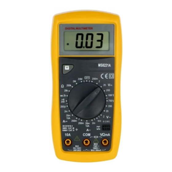
1.4 MAINTENANCE - Please do not attempt to adjust or repair the meter by removing the rear case while voltage is being applied. A technician who fully understands danger involved should only carry out such actions. - Before opening the battery cover or case of the meter, always disconnect test leads from all tested circuits. - Page 8 - Single operation of a transform switch makes measurement convenient. Overload protection and low battery indication are provided, this meter is ideal for use in the fields, workshop, school, hobby and home applications. - This meter is with the functions of data hold. NAME OF COMPONENTS 1.
-
Page 9: Specifications
3 SPECIFICATIONS 3.1 GENERAL SPECIFICATIONS - Environment conditions: 600V CAT.III Pollution degree: 2. Altitude < 2000 m. - Operating temperature: 0~40 (32℉ 104℉), (<80% non-condensing) - Storage temperature: -10~50 C(14℉ to 122℉), (<70% RH, battery... -
Page 10: Measurement Specifications
removed) - Temperature Coefficient: 0.1×(specified accuracy) / C (<18 C or >28 - MAX. Voltage between terminals and earth ground: 600V AC rms or 600V DC - Fuse Protection: mA: F 250mA/600V ∅6.3×32, 10A: 10A/600V ∅6.3×32 - Display: LCD, 1999counts, updates 2-3/sec. - Over Range indication: LCD will display "1". -
Page 11: Dc Voltage
3.2.1 DC VOLTAGE Accuracy Range Resolution A/B/D model C model 0.2V 0.1mV ±0.5%±2 ±0.5%±2 ±0.5%±3 0.01V ±0.5%±3 ±0.8%±3 200V 0.1V 600V ±0.8%±2 ±0.8%±5 - Input impedance: A/B/D model: 10MΩ C model: 1MΩ - Max. input voltage: 200mV range: 250VDC or AC 2V - 600V ranges: 600VDC or 600V rms 3.2.2 AC VOLTAGE Accuracy... -
Page 12: Dc Current
2V -600V ranges: 600VDC or 600V rms - Frequency range: A/B/D model: 40Hz-1000Hz C model: 40Hz-400Hz - Response: Average, calibrated in rms of sine wave. 3.2.3 DC CURRENT Accuracy Range Resolution D model C model A/B model 200uA 0.1uA ±0.8%±2 NULL NULL 1 uA... -
Page 13: Resistance
Frequency Range: 40Hz-1kHz Indication: Average (rms of sine wave) 3.2.5 Resistance Accuracy Range Resolution A/B/D model C model 200Ω 0.1Ω ±0.8%±3 ±1.0%±3 2KΩ 1Ω 20KΩ 10Ω ±0.8%±2 ±1.0%±2 200KΩ 100Ω ±1.0%±2 ±0.8%±2 2MΩ 1kΩ 20MΩ 10kΩ ±1.0%±2 Overload protection: 250V DC or 250V AC rms. 3.2.6 Diode test Display: read approximate forward voltage of diode... -
Page 14: Audible Continuity Test (Only B Model)14
Open circuit voltage: approx. 2.8V Overload protection: 250V DC or 250V AC rms 3.2.8 Audible continuity test (Only B model) Range Description Test Condition Base Current Display read approx. approx. 10μA, HFE value (0-1000) of Vce approx. transistor under test (all 2.8V. -
Page 15: Operating Instruction
4 OPERATING INSTRUCTION 4.1 Voltage measurement - Set rotary switch to the desired V or V~ range. - Connect the black and red test leads to the COM and V terminals respectively. - Connect the test leads to the circuit being measured - Read the displayed value. - Page 16 the red test leads to the mA terminal for a maximum of 200mA. For a maximum of 10A, move the red test lead to the 10A terminal. - Connect test leads in series with the load in which the current is to be measured. - Read the displayed value.
-
Page 17: Resistance Measurement
Resistance measurement - Connect the black test lead to the COM jack and the red test lead to the Ω jack. - Set the transform switch at the Ω range position. - Connect test leads across the resistance under measurement. - You can get reading from LCD. -
Page 18: Continuity Test
- The meter will show the approx. forward voltage of the diode. If the lead connection is reversed, only figure "1" displayed. To avoid electrical shock and/or damage to the instrument, disconnect circuit power and discharge all high-voltage capacitors before testing diodes. -
Page 19: Battery Test (Only D Model)
- The LCD display will show the current environment temperature. When measuring temperature with thermocouple, ‘K’ type probe for this meter can be used. Insert the black plug to the COM jack and the red one to the TEMP jack, touch the end of the temperature sensor to the area or surface of the object for measurement. -
Page 20: Transistor Measurement (Only B Model)
Transistor measurement (only B model) To avoid electrical shock and/or damage to the instrument, before attempting insert transistors for testing, always be sure that test leads have been disconnected from any measurement circuits. Set the rotary switch to hFE range, plug the transistor adpertor. -
Page 21: Fuse Replacement
Soak a new swab with a cleaning and oiling agent (such as WD-40). Work the swab around in each terminal. The oiling agent insulates the terminals from moisture-related contamination. To avoid electrical shock or damage to the meter, do not get water inside the case. Remove the test leads and any input signals before opening the case 5.2 Fuse replacement... -
Page 22: Battery Replacement
5.3 Battery replacement To replace the battery (see the Figure): - When the battery voltage drop below proper operation range the symbol will appear on the LCD display and the battery need to be replaced. - Turn the meter off and remove all test leads. - Use a screwdriver to unscrew the two screws secured on the battery cover, and remove the battery cover. - Page 24 CAUTION Using this appliance in an environment with a strong radiated radio-frequency electromagnetic field (approx. 3V/m), may influence its measuring accuracy. The measuring result can be strongly deviating from the actual value.
Need help?
Do you have a question about the MS8221 and is the answer not in the manual?
Questions and answers