Table of Contents
Advertisement
Quick Links
Contents
TITLE
3.1.5
.........................................................
.........................................................
.........................................................
.........................................................
.........................................................
.........................................................
.........................................................
.........................................................
.........................................................
.........................................................
.........................................................
.........................................................
.........................................................
.........................................................
.........................................................
.........................................................
.........................................................
.........................................................
.........................................................
.........................................................
.........................................................
PAGE
1
1
1
3
4
4
6
6
7
9
10
10
10
11
11
12
12
13
13
14
15
Advertisement
Table of Contents

Related Manuals for V&A VA41


Summary of Contents for V&A VA41
-
Page 1: Table Of Contents
Contents TITLE PAGE ………………………………………………… 1. GENERAL INSTRUCTIONS 1.1 Precaution safety measures ………………………………………………… 1.1.1 Preliminary ………………………………………………… 1.1.2 During use ………………………………………………… 1.2 Symbols ………………………………………………… 1.3 Instructions ………………………………………………… ………………………………………………… 2. DESCRIPTION 2.1 Instrument Familiarization ………………………………………………… 2.2 LCD Display ………………………………………………… 2.3 Key pad ………………………………………………… …………………………………………………... - Page 2 TITLE PAGE 3.2.4 Continuity Check ………………………………………………… 3.2.5 Diode Test ………………………………………………… 3.2.6 Capacitance measurement ………………………………………………… 3.2.7 Current measurement ………………………………………………… ………………………………………………… 4. TECHNICAL SPECIFICATIONS 4.1 General specifications.. ………………………………………………… 4.2 Measurement specifications ………………………………………………… 4.2.1 AC Voltage ………………………………………………… 4.2.2 DC Voltage ………………………………………………… 4.2.3 Resistance …………………………………………………...
-
Page 3: General Instructions
6000 COUNTS DIGITAL MULTIMETER USER'S MANUAL 1. GENERAL INSTRUCTIONS This instrument complies with IEC 61010-1:2001, CAT 1000V and CAT Ⅵ 600V overvoltage standards. See Specifications. To get the best service from this instrument, read carefully this user's manual and respect the detailed safety precautions. - Page 4 6000 COUNTS DIGITAL MULTIMETER USER'S MANUAL Overvoltage In brief Examples category • Protected electronic equipment. • Equipment connected to (source) circuits in which measures are taken to CATⅠ Electronic limit transient overvoltages to an appropriately low level. • Any high-voltage, low-energy source derived from a highwinding resistance transformer, such as the high-voltage section of a copier.
-
Page 5: During Use
6000 COUNTS DIGITAL MULTIMETER USER'S MANUAL 1.1.2 During use * If the meter is used near noise generating equipment, be aware that display may become unstable or indicate large errors. * Do not use the meter or test leads if they look damaged. * Use the meter only as specified in this manual;... -
Page 6: Symbols
6000 COUNTS DIGITAL MULTIMETER USER'S MANUAL * In TV repair work, or when carrying out measurements on power switching circuits, remember that high amplitude voltage pulses at the test points can damage the multimeter. Use of a TV filter will attenuate any such pulses. * Use just one 6F22 battery, properly installed in the Meter's battery case, to power the Meter. - Page 7 6000 COUNTS DIGITAL MULTIMETER USER'S MANUAL * Any adjustment, maintenance or repair work carried out on the meter while it is live should be carried out only by appropriately qualified personnel, after having taken into account the instructions in this present manual. * A "qualified person"...
-
Page 8: Description
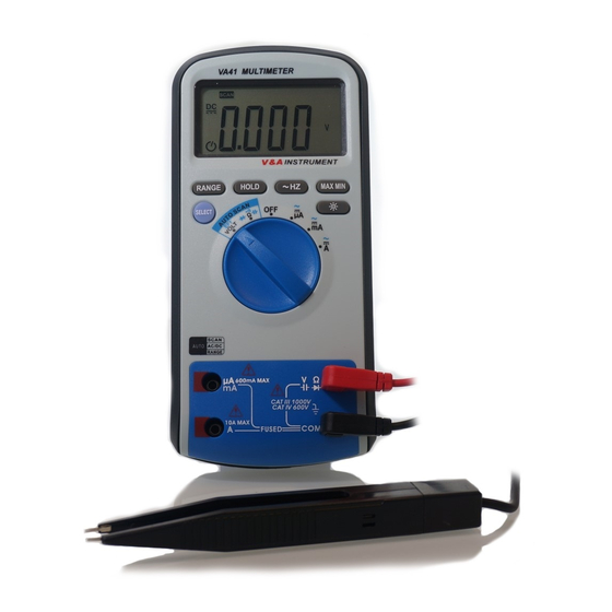
6000 COUNTS DIGITAL MULTIMETER USER'S MANUAL 2. DESCRIPTION 2.1 Instrument Familiarization The front panel is shown as in Figure 2-1, explanation being as follows: ○ ,1 LCD display Used for displaying the measuring results and various symbols. ○ ,2 Keypad Measurement function keys. -
Page 9: Lcd Display
6000 COUNTS DIGITAL MULTIMETER USER'S MANUAL 2.2 LCD Display Figure 2-2... - Page 10 6000 COUNTS DIGITAL MULTIMETER USER'S MANUAL LCD screen is shown as in Figure 2-2, with its every symbol’s meaning shown as in the Table 1: Symbol Meaning Indicator for auto power off Indicates negative readings Indicator for AC voltage or current Indicator for DC voltage or current Unsafe voltage.
-
Page 11: Keypad
6000 COUNTS DIGITAL MULTIMETER USER'S MANUAL 2.3 Keypad 2.3.1 SELECT (1) When the meter is turned off and the rotary switch is not in position of OFF, press SELECT key for 2 seconds to turn on the meter and press the key once more >2sec. to turn the power OFF. (2)... -
Page 12: Function Description
6000 COUNTS DIGITAL MULTIMETER USER'S MANUAL again it will return the voltage or current measurement state 2.3.5 MAX/MIN This key is for measuring maximum value and minimum value. 1. Press it to enter Max/Min mode and simultaneously display the maximum value. 2. -
Page 13: Data Hold Mode
6000 COUNTS DIGITAL MULTIMETER USER'S MANUAL ACmA 3.00mA~600.0mA (60Hz) 0.01A~10A 3.00A~10A (60Hz) 3.1.2 DATA HOLD mode Data Hold mode makes the meter stop updating the display. Enabling Data Hold function in autorange mode makes the meter switch to Manual ranging mode, but the full-scale range remains the same. Data Hold function can be cancelled by changing the measurement mode, pressing RANGE key, or push HOLD key again. -
Page 14: True Rms Measurement
6000 COUNTS DIGITAL MULTIMETER USER'S MANUAL 3.1.4 TRUE RMS measurement All the measurement values of the true RMS meter on the AC voltage and AC current are true root-mean-square values. The basic meter can only measure the AC average value. 3.1.5 Auto power off setting When the meter is powered on, it is under auto power off mode. -
Page 15: Measurement Functions
6000 COUNTS DIGITAL MULTIMETER USER'S MANUAL 3.2 Measurement Functions 3.2.1 AC and DC Voltage measurement To avoid electrical shock and/or damage to the instrument, do not attempt to take any voltage measurement that might exceeds 1000Vdc or 1000Vac rms. To avoid electrical shock and/or damage to the instrument, do not apply more than 1000Vdc or 1000Vac rms between the common terminal and the earth ground. -
Page 16: Non-Contact Electric Field Detector (Ef Mode)
6000 COUNTS DIGITAL MULTIMETER USER'S MANUAL 3.2.2 Non-contact electric field detector (EF mode) It should be a long-distance in measuring high-voltage. Pay attention to safety Electric field is a special substance exist in the charge and the variable ambient magnetic field. To detector Non-contact electric field (set up and connect the Meter as shown in Figure 3-2): 1 Set the rotary switch to the position of EF/VOLT. -
Page 17: Resistance Measurement
6000 COUNTS DIGITAL MULTIMETER USER'S MANUAL 3.2.3 Resistance measurement To avoid electrical shock and/or damage to the instrument, disconnect circuit power and discharge high-voltage capacitors before measuring resistance. Resistance is an opposition to current flow. The unit of resistance is the ohm (Ω). The Meter measures resistance by sending a small current through the circuit. -
Page 18: Continuity Check
6000 COUNTS DIGITAL MULTIMETER USER'S MANUAL 3.2.4 Continuity Check To avoid electrical shock and/or damage to the instrument, disconnect circuit power and discharge high-voltage capacitors before testing Continuity. Continuity is a complete path for current flow. The beeper sounds if a circuit is complete. These brief contacts cause the Meter to emit a short beep To test for continuity (set up the Meter as shown in Figure 3-4): 1. -
Page 19: Diode Test
6000 COUNTS DIGITAL MULTIMETER USER'S MANUAL 3.2.5 Diode Test To avoid electrical shock and/or damage to the instrument, disconnect circuit power and discharge all high-voltage capacitors before testing diodes. Use the diode test to check diodes, transistors, and other semiconductor devices. The diode test sends a current through the semiconductor junction, then measures the voltage drop across the junction, A good silicon junction drops between 0.5V and 0.8V. -
Page 20: Capacitance Measurement
6000 COUNTS DIGITAL MULTIMETER USER'S MANUAL 3.2.6 Capacitance measurement To avoid electrical shock and/or damage to the instrument, disconnect circuit power and discharge high-voltage capacitors before measuring capacitance. Use the dc voltage function to confirm that the capacitor is discharged. Capacitance is the ability of a component to store an electrical charge. -
Page 21: Current Measurement
6000 COUNTS DIGITAL MULTIMETER USER'S MANUAL 3.2.7 Current measurement To avoid damage to the Meter or injury if the fuse blows, never attempt in-circuit current measurement where the open-circuit potential to earth is greater than 1000V. To avoid damage to the meter, check the meter's fuse before proceeding. -
Page 22: Technical Specifications
6000 COUNTS DIGITAL MULTIMETER USER'S MANUAL 4. TECHNICAL SPECIFICATIONS 4.1 General specifications Environment conditions: 1000V CAT Ⅲ and 600V CAT Ⅳ Pollution degree: 2 Altitude < 2000m Operating temperature: 0~40℃, 32℉~122℉(<80% RH, <10℃ non-condensing) Storage temperature: -10~60 ℃, 14℉~140℉(<70% RH, battery removed) Temperature Coefficient: 0.1×(specified accuracy) / ℃... -
Page 23: Ac Voltage
6000 COUNTS DIGITAL MULTIMETER USER'S MANUAL 4.2.1 AC Voltage ACV: Accuracy Range Resolution 60Hz 40Hz~400Hz 600mV 0.1mV ±(1.0% +3) ±(1.0% +3) 10mV ±(1.0% +3) 600V 100mV ±(1.0% +3) 1000V ±(1.5% +5) Above accuracies can be guaranteed within 5%~100% of the full range. The true RMS meter has residual value within 10 counts when the test leads are shorten, but that will not affect the accuracy of measurement. -
Page 24: Resistance
6000 COUNTS DIGITAL MULTIMETER USER'S MANUAL 4.2.3 Resistance Range Resolution Accuracy 600.0Ω 0.1Ω 6.000kΩ 1Ω 60.00kΩ 10Ω ±(1.2% +2) 600.0kΩ 100Ω 6.000MΩ 1kΩ 60.00MΩ 10kΩ ±(2% +5) 4.2.4 Continuity Check Function Range Resolution 600Ω 0.1Ω Description: Continuity beeper≤30Ω 4.2.5 Diode Test Range Resolution Test Condition... -
Page 25: Current
6000 COUNTS DIGITAL MULTIMETER USER'S MANUAL 4.2.7 Current DCA: Range Resolution Accuracy 600μA 0.1μA ±(1.0% +3) 6000μA 1μA 60mA 0.01mA ±(1.5% +3) 600mA 0.1mA 10mA ±(1.8% +5) ACA: Range Resolution Accuracy 600μA 0.1μA ±(1.5% +5) 6000μA 1μA 60mA 0.01mA ±(1.8% +8) 600mA 0.1mA 10mA... -
Page 26: Maintenance
6000 COUNTS DIGITAL MULTIMETER USER'S MANUAL Range Resolution Accuracy 6kHZ 0.001HZ ±(0.05% +8) 10KHZ 0.01HZ Above accuracies can be guaranteed within 10%~100% of the full range. 5. MAINTENANCE This section provides basic maintenance information, including fuse and battery replacement instructions. Do not attempt to repair or service your Meter unless you are qualified to do so and have the relevant calibration, performance test, and service information. -
Page 27: Battery Replacement
6000 COUNTS DIGITAL MULTIMETER USER'S MANUAL 1. Set rotary switch to the OFF position. 2. Disconnect test leads and/or any connectors from the terminals. 3. Use a screwdriver to unlock the four screws on the rear cover. 4. Take out the rear cover from the meter. 5.
Need help?
Do you have a question about the VA41 and is the answer not in the manual?
Questions and answers