Table of Contents
Advertisement
Quick Links
Advertisement
Table of Contents

Related Manuals for Micro Detectors SB400


Summary of Contents for Micro Detectors SB400
- Page 1 SB400 M.D. Micro Detectors Strada S. Caterina, 235 LANGUAGE 41122 Modena Italy Safety Modules Tel. +39 059 420411 Fax +39 059 253973 Installation and Operation Manual ENGLISH www.microdetectors.com info@microdetectors.com M.D. Micro Detectors CAT8ESB1261001 1/14...
-
Page 2: Table Of Contents
SB400 M.D. Micro Detectors Strada S. Caterina, 235 LANGUAGE 41122 Modena Italy Safety Modules Tel. +39 059 420411 Fax +39 059 253973 Installation and Operation Manual ENGLISH www.microdetectors.com info@microdetectors.com CONTENTS 1.0 INTRODUCTION ..........................3 2.0 SB400 MODULE ..........................4 2.1 OPERATING MODES DESCRIPTION ..................... 4 2.1.1 AUTOMATIC ........................4 2.1.2... -
Page 3: Introduction
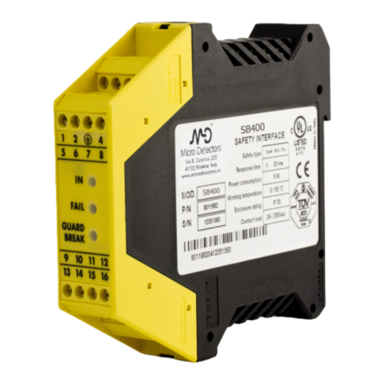
1.0 INTRODUCTION The SB400 interface, connected to an IEC 61496 – ½ certified type 4 safety light curtain and equipped with two auto controlled PNP type solid-state outputs, is a type 4 ESPE (Electro sensitive Protective Equipment). -
Page 4: Sb400 Module
41122 Modena Italy Safety Modules Tel. +39 059 420411 Fax +39 059 253973 Installation and Operation Manual ENGLISH www.microdetectors.com info@microdetectors.com 2.0 SB400 MODULE 2.1 OPERATING MODES DESCRIPTION OPERATING MODES SELECTION TERMINAL 5 TERMINAL 6 OPERATION 0 Vdc +24 Vdc Automatic... -
Page 5: Manual
SB400 M.D. Micro Detectors Strada S. Caterina, 235 LANGUAGE 41122 Modena Italy Safety Modules Tel. +39 059 420411 Fax +39 059 253973 Installation and Operation Manual ENGLISH www.microdetectors.com info@microdetectors.com 2.1.2 MANUAL In this operating mode, the outputs of the control unit are activated only if the protected area is free and after sending the RESTART signal to the control unit using the push-button or by means of a specific command on the RESTART input (terminal 4). -
Page 6: Signal Description
The SYSTEM RESET TIME is obtained adding the reset time of any external contactors • K1K2 to the reset time of the SB400 control unit (100 ms). In the case of manual activation, a normally open external button can be used, temporary •... -
Page 7: K1K2 Feedback Input
! Install the SB400 control unit in an environment with a protection rating of at least IP54. ! If more modules SB400 must be installed in the same board panel, in order to avoid overheating, maintain between them one minimal distance of 2 cm. -
Page 8: Use Of K1 And K2 Auxiliary Contact Elements
SB400 M.D. Micro Detectors Strada S. Caterina, 235 LANGUAGE 41122 Modena Italy Safety Modules Tel. +39 059 420411 Fax +39 059 253973 Installation and Operation Manual ENGLISH www.microdetectors.com info@microdetectors.com 2.3.2 Use of K1 and K2 auxiliary contact elements For loads with higher voltage and current characteristics than those indicated in the table above, use of auxiliary external relays or contactors suitable for the load to be controlled is recommended. -
Page 9: Status Indicators
Yellow Barrier free – Output relays opened YELLOW (only in manual mode) Table 3 * M.D. MICRO DETECTORS TO THE “FAULT DIAGNOSI” SECTION TO HAVE A DETAILED EXPLANATION OF THE POSSIBLE FAULT Figure 5 2.5 DIMENSIONS Figure 6 M.D. Micro Detectors... -
Page 10: Technical Data Sb400
41122 Modena Italy Safety Modules Tel. +39 059 420411 Fax +39 059 253973 Installation and Operation Manual ENGLISH www.microdetectors.com info@microdetectors.com 2.6 TECHNICAL DATA SB400 Safety category Power supply 24 ± 20% Power requirement 5 max Output Relay 2 N.O. contacts (2 A; 250 Vac) System Status Output 100 mA;... -
Page 11: Status Indicators / Fault Diagnosis
(7 pulses) SYSTEM STATUS connection error Table 6 ! If it is not possible to clearly identify the malfunction and to to remedy it, stop the machine and contact the M.D. MICRO DETECTORS's Assistence Service. M.D. Micro Detectors CAT8ESB1261001 11/14... -
Page 12: Periodic Tests To Do Every Year
SB400 M.D. Micro Detectors Strada S. Caterina, 235 LANGUAGE 41122 Modena Italy Safety Modules Tel. +39 059 420411 Fax +39 059 253973 Installation and Operation Manual ENGLISH www.microdetectors.com info@microdetectors.com 2.8 PERIODIC TESTS TO DO EVERY YEAR M.D. Micro Detectors CAT8ESB1261001... - Page 13 SB400 M.D. Micro Detectors Strada S. Caterina, 235 LANGUAGE 41122 Modena Italy Safety Modules Tel. +39 059 420411 Fax +39 059 253973 Installation and Operation Manual ENGLISH www.microdetectors.com info@microdetectors.com M.D. Micro Detectors CAT8ESB1261001 13/14...
-
Page 14: Guarantee
Validity of this warranty is regulated by the following conditions: • The user must inform M.D. Micro Detectors of the fault within 24 months from the date of delivery of the product.
Need help?
Do you have a question about the SB400 and is the answer not in the manual?
Questions and answers