Table of Contents
Advertisement
Quick Links
Contents
Product overview ·························································································································································· 1
Preparing for installation ············································································································································· 3
Safety recommendations ·················································································································································· 3
Temperature and humidity requirements ························································································································ 3
Accessories provided with the AP ··································································································································· 3
Installation tools ································································································································································· 4
Installing the AP ···························································································································································· 5
Check before installation ·················································································································································· 5
Determining the installation position ······························································································································· 6
Installing antennas ···························································································································································· 6
Installing the AP ································································································································································· 6
Mounting the AP on a wall······································································································································ 7
Installing the AP on a ceiling ······························································································································· 11
Connecting the AP to the power supply ······················································································································ 14
Check before power-on ········································································································································ 14
Connecting PoE power supply ····························································································································· 14
Connecting local power supply ··························································································································· 15
Check after power-on············································································································································ 15
Connecting the AP to the network ································································································································ 15
Verifying network connection for the fit AP ········································································································ 15
Verifying network connection for the fat AP ······································································································· 16
Logging in to the AP··················································································································································· 17
Logging in through the console port ···························································································································· 17
Setting up the configuration environment ··········································································································· 17
Connecting the console cable ······························································································································ 17
Setting terminal parameters ·································································································································· 18
Logging in through the console port ···················································································································· 19
Logging in through Telnet or Web ······························································································································· 20
Appendix LEDs and ports ·········································································································································· 21
LEDs ················································································································································································· 21
Ports ················································································································································································· 21
Index ··········································································································································································· 24
i
Advertisement
Table of Contents

Related Manuals for H3C WA4600 Series


Summary of Contents for H3C WA4600 Series
-
Page 1: Table Of Contents
Contents Product overview ·························································································································································· 1 Preparing for installation ············································································································································· 3 Safety recommendations ·················································································································································· 3 Temperature and humidity requirements ························································································································ 3 Accessories provided with the AP ··································································································································· 3 Installation tools ································································································································································· 4 Installing the AP ···························································································································································· 5 ... -
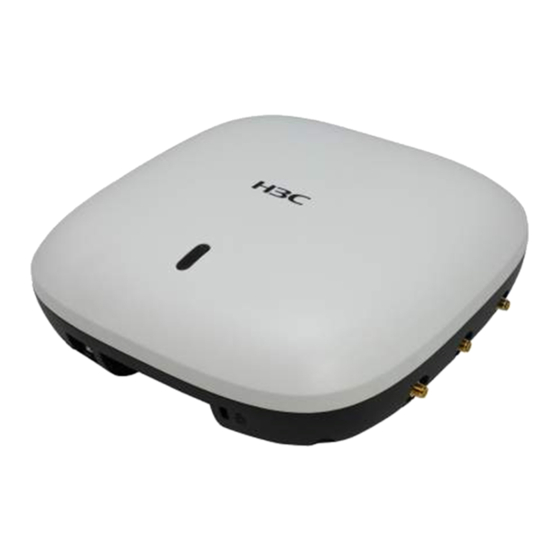
Page 2: Product Overview
Product overview H3C WA4600 Series Indoor Access Points (WA4600 series) include the models WA4620i-ACN and WA4620E-ACN. The WA4620i-ACN AP uses built-in antennas. The WA4620E-ACN AP uses external antennas. The WA4600 AP can act as a fit AP to cooperate with wireless switches or access controllers (ACs) to provide wireless access for WLAN users. - Page 3 72 × 220 × 220 mm (2.83 × 8.66 × (H × W × D) 8.66 in) Weight 1.5 kg (3.31 lb) 1.4 kg (3.09 lb) NOTE: The WA4620E-ACN AP is not provided with antennas. You need to order antennas for the WA4620E-ACN AP from H3C.
-
Page 4: Preparing For Installation
Preparing for installation Safety recommendations WARNING! Only qualified personnel can install and remove the AP and its accessories. You must read all safety instructions supplied with the AP before installation and operation. To avoid possible bodily injury and equipment damage, read the following safety recommendations before installing the AP. -
Page 5: Installation Tools
MAC address label Console cable (for fat AP only) M4 × 10 pan head screw Installation tools When installing the AP, you may need the following tools. Prepare these tools yourself. Level Crimping pliers RJ-45 crimping pliers Wire-stripping pliers Pincer pliers Percussion drill with matching Rubber hammer... -
Page 6: Installing The Ap
Installing the AP IMPORTANT: The AP is typically installed on a high position. H3C recommends that you log in to and configure the AP before the installation. For more information about logging in to the AP, see “Logging in to the AP.”... -
Page 7: Determining The Installation Position
The ceiling for installing the AP must be less than 18 mm (0.71 in) in thickness, and can bear a load • of 5 kg (1 1.02 lb). H3C recommends that you reinforce the ceiling by using boards if it the ceiling is not strong enough. -
Page 8: Mounting The Ap On A Wall
To install the AP on a wall or ceiling, you need a mounting bracket. Figure 5 shows the installation holes in the mounting bracket. Figure 5 Mounting bracket installation holes (with a diameter of 4.5 mm (0.18 in) The mounting bracket includes an AP bracket and a wall/ceiling bracket. To install the AP on a wall or ceiling, attach the AP bracket to the AP and the wall/ceiling bracket to the wall or ceiling. - Page 9 Figure 7 Attaching the AP bracket to the AP rear Mark the installation holes on the wall by using the wall/ceiling mounting bracket, as shown Figure...
- Page 10 Figure 8 Marking installation holes on the wall Drill three holes with a diameter of 5 mm (0.197 in) and a depth of 30 mm (1.18 in) in the marked locations, as shown in Figure Figure 9 Drilling holes in the wall Insert a wall anchor into each hole, and tap the wall anchor with a rubber hammer until it is all flush with the wall surface, as shown in Figure...
- Page 11 Figure 10 Hammering the anchor Align the holes in the wall/ceiling bracket with the anchors and insert screws through the installation holes into the wall anchors. Adjust the position of the mounting bracket and tighten the screws. Figure 11 Attaching the wall/ceiling bracket to the wall Connect the AP to the LAN by using Ethernet cables.
-
Page 12: Installing The Ap On A Ceiling
Figure 12 Aligning the AP with the wall/ceiling bracket Figure 13 Attaching and rotating the AP Figure 14 Locking the AP bracket and the wall/ceiling mounting bracket Installing the AP on a ceiling Align the positioning posts on the AP bracket with the positioning holes in the AP rear. Use the M4 ×... - Page 13 Figure 15 Attaching the AP bracket to the AP rear Mark the installation holes on the ceiling by using the wall/ceiling bracket. Drill three holes with a diameter of 5 mm (0.197 in) in the marked positions, as shown in Figure...
- Page 14 Figure 16 Drilling holes in the ceiling Insert the M4 × 30 screws through the holes in the wall/ceiling bracket and the holes in the ceiling. Fasten washers and nuts at the other side of the ceiling to attach the wall/ceiling bracket to the ceiling, as shown in Figure Figure 17 Attaching the wall/ceiling bracket to the ceiling...
-
Page 15: Connecting The Ap To The Power Supply
Figure 18 Mounting the AP to the ceiling Verify that the AP is securely installed to prevent it from falling off. Connecting the AP to the power supply The AP supports PoE and local power supply. You can choose the power supply mode as required. Check before power-on Check the following items before powering on the AP: •... -
Page 16: Connecting Local Power Supply
Connecting local power supply NOTE: The AC/DC adapter and power cord are user-supplied. Table 2 Power adapter specifications Item Specification Input 100 VAC to 240 VAC Output +48V at 0.52 A The AP supports AC/DC adapters. You can connect the power port of the AP to the power source through an AC/DC adapter to supply power to the AP. -
Page 17: Verifying Network Connection For The Fat Ap
AP Profiles State : I = Idle, J = Join, JA = JoinAck, IL = ImageLoad C = Config, R = Run, KU = KeyUpdate, KC = KeyCfm -------------------------------------------------------------------------------- AP Name State Model Serial-ID -------------------------------------------------------------------------------- WA4620E-ACN 210235A1BUB139000435 ------------------------------------------------------------------------------- Verifying network connection for the fat AP Use the ping command on the fat AP to ping the uplink network device. -
Page 18: Logging In To The Ap
Logging in to the AP IMPORTANT: The AP is typically installed on a high position. H3C recommends that you log in to the AP before the installation. This section applies only when the AP acts as a fat AP. When the AP operates as a fat AP, you can log in to the AP through the console port, or through Telnet or Web to configure the AP. -
Page 19: Setting Terminal Parameters
Setting terminal parameters Start the PC and run the terminal emulation program such as the HyperTerminal of Windows 95/98/NT/2000/XP. Select Start > All Programs > Accessories > Communications > HyperTerminal, and in the Connection Description dialog box that appears, type the name of the new connection in the Name text box and click OK. -
Page 20: Logging In Through The Console Port
Figure 24 Setting the serial port parameters NOTE: To use the default settings, click Restore Defaults. Click OK and the system displays the HyperTerminal window. Figure 25 HyperTerminal window Logging in through the console port Power on the AP, and you can see the following information: System is starting... -
Page 21: Logging In Through Telnet Or Web
User interface con0 is available. Press ENTER to get started. Logging in through Telnet or Web By default, Telnet login and Web login are enabled. You can log in to the AP by using the following default login information: • Username—admin. -
Page 22: Appendix Leds And Ports
• Slowly pulsing green twice and slowly pulsing blue twice—Clients exist on the 2.4G blue and 5G radio interfaces. NOTE: H3C Access Controllers Configuration Guides For more information about the blink mode, see Ports Table 4 AP ports Item WA4620i-ACN WA4620E-ACN •... - Page 23 Figure 26 Ports on the WA4620i-ACN AP (1) Security slot (2) Power port (3) 10/100/1000 Mbps copper Ethernet port 1 (4) 10/100/1000 Mbps copper Ethernet port 2 (5) Console port (6) Reset button Table 5 Port description for the WA4620i-ACN AP Port mark Standards and protocols Description...
- Page 24 Figure 27 Ports on the WA4620E-ACN AP (1 to 3) 5G antenna feed ports 1 to 3 (4) Security slot (5) Power port (6) 10/100/1000 Mbps copper Ethernet port 1 (7) 10/100/1000 Mbps copper Ethernet port 2 (8) Console port (9) Reset button (10 to 12) 2.4G antenna feed ports 1 to 3 Table 6 Port description for the WA4620E-ACN AP...
-
Page 25: Index
Index accessories for AP installation, data bits (parameter), antenna determining installation position, installation, electrical ceiling-mounting, connecting console cable, connecting console cable, connecting local power supply, console port access, 17, connecting PoE power supply, installation, 5, connecting power supply, installation accessories, emulation (parameter), installing antenna, environment... - Page 26 logging safety installation site humidity, logging through console port installation site temperature, AP, 17, recommendations, logging through Telnet setting AP configuration environment, logging through Web terminal parameters, site login humidity, temperature, stop bits (parameter), network connection verification fat AP, technical specifications fit AP, LED, networking...
Need help?
Do you have a question about the WA4600 Series and is the answer not in the manual?
Questions and answers