Advertisement
Quick Links
INSTALLATION INSTRUCTIONS
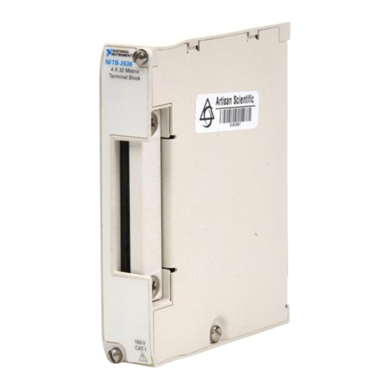
NI TB-2636
4 × 32 2-Wire Terminal Block for the NI PXI-2529
Introduction
Caution
This terminal block is rated for Measurement Category I and intended to carry
signal voltages no greater than 150 V. This module can withstand up to 800 V impulse
voltage. Do not use this module for connection to signals or for measurements within
Categories II, III, or IV. Do not connect to MAINS supply circuits (for example, wall
outlets) of 115 or 230 VAC. Refer to the Read Me First: Safety and Radio-Frequency
Interference document for more information on measurement categories.
When module terminals are hazardous voltage LIVE (> 42.4 Vpk/60 VDC), you must
ensure that devices and circuits connected to the module are properly insulated from
human contact.
Conventions
»
This document describes how to install and connect signals to the
National Instruments TB-2636 terminal block. Refer to the NI Switches
Getting Started Guide to determine when to install the NI TB-2636.
The NI TB-2636 terminal block installs in front of the NI PXI-2529 switch
module and has screw terminals that provide access to the rows and
columns of the matrix.
The following conventions are used in this document:
The » symbol leads you through nested menu items and dialog box options
to a final action. The sequence File»Page Setup»Options directs you to
pull down the File menu, select the Page Setup item, and select Options
from the last dialog box.
Advertisement

Related Manuals for National Instruments NI TB-2636


Summary of Contents for National Instruments NI TB-2636
- Page 1 Getting Started Guide to determine when to install the NI TB-2636. Introduction The NI TB-2636 terminal block installs in front of the NI PXI-2529 switch module and has screw terminals that provide access to the rows and columns of the matrix.
- Page 2 Notify NI if the terminal block appears damaged in any way. Do not install a damaged terminal block on a switch module. Store the terminal block in the antistatic package when not in use. NI TB-2636 Installation Instructions ni.com...
-
Page 3: Connect Signals
2. Verify the Components Make sure you have the following: ❑ NI TB-2636 terminal block ❑ PXI chassis ❑ NI PXI-2529 switch module ❑ 1/8 in. flathead screwdriver 3. Connect Signals To connect signals to the terminal block, complete the following steps while referring to Figure 1. - Page 4 6 Safety Ground Lug 2 Strain-Relief Opening 7 Terminal Block Top Cover 3 Signal Wires 8 Top Cover Screw 4 Strain-Relief Screw 9 Rear Connector 5 Jackscrew 10 Screw Terminals Figure 1. NI TB-2636 Terminal Block NI TB-2636 Installation Instructions ni.com...
- Page 5 C31- C26+ C19- C22+ C26- C22- C27+ C23+ C27- C23- IF HIGH VOLTAGE IS PRESENT, CONNECT A SAFETY WARNING: EARTH GROUND TO THE SAFETY GROUND LUG. Figure 2. NI TB-2636 Terminal Reference © National Instruments Corporation NI TB-2636 Installation Instructions...
-
Page 6: Install The Terminal Block
4. Install the Terminal Block To connect the NI TB-2636 terminal block to the NI PXI-2529 front panel, complete the following steps while referring to Figure 3. Connect the NI PXI-2529 front connector to its mating connector on the terminal block. -
Page 7: Compliance And Certifications
Waste Electrical and Electronic Equipment (WEEE) EU Customers At the end of their life cycle, all products must be sent to a WEEE recycling center. For more information about WEEE recycling centers and National Instruments WEEE initiatives, visit ni.com/environment/weee.htm © National Instruments Corporation... - Page 8 National Instruments, NI, ni.com, and LabVIEW are trademarks of National Instruments Corporation. Refer to the Terms of Use section on ni.com/legal for more information about National Instruments trademarks. Other product and company names mentioned herein are trademarks or trade names of their respective companies. For patents covering National Instruments products, refer to the appropriate location: Help»Patents in your software, the patents.txt file on your CD, or ni.com/patents.
- Page 9 取り付け手順 NI TB-2636 32 NI PXI-2529 × 用 線式端子台 TB-2636 このドキュメントでは、ナショナルインスツルメンツ製 端子台 NI TB-2636 の取り付け方、また信号の接続方法について説明しています。 を取り付ける順番については、 『 スイッチスタートアップガイド』を参 照してください。 はじめに NI TB-2636 NI PXI-2529 端子台は スイッチモジュールの前面に取り付け、 ネジ留め式端子でマトリクスの行と列へ接続します。 Measurement Category I 注意 この端子台は、 に定格されているため、使用できる 150 V 800 V 信号電圧は 以下で、 最大...
- Page 10 ど、ソフトウェアで選択またはクリックする必要がある項目を表します。 また、 太字のテキストは、パラメータ名も表します。 斜体 斜体のテキストは、変数、強調、相互参照、または重要な概念の説明を示 します。 また、入力する必要のある言葉や値を表すこともあります。 このフォントのテキストは、キーボードから入力する必要があるテキスト monospace や文字、コードの一部、プログラムサンプル、構文例を表します。 また、 ディスクドライブ、パス、ディレクトリ、プログラム、サブプログラム、 サブルーチンなどの名称、デバイス名、関数、操作、変数、ファイル名お よび拡張子の引用にも使用されます。 端子台を箱から取り出す 端子台は、部品に破損をもたらす静電放電( )を防止するために静電 気防止用パッケージに包装されて出荷されています。 このような破損を回 避するには、以下の予防措置を行ってください。 注意 露出しているコネクタピンには絶対に触れないでください。 • 接地ストラップを使用したり、接地された物体に触れて、身体を接地 する。 • 静電気防止用パッケージをシャーシの金属部分に接触させてから、 端子台をパッケージから取り出す。 端子台を箱から取り出し、部品がゆるんでいないかどうか、また、破損箇 所がないかどうか調べます。 端子台が破損している場合は、ナショナルイ ンスツルメンツまでご連絡ください。 破損している端子台をスイッチモ ジュールに取り付けないでください。 端子台は、使用しないときは静電気防止用パッケージに入れて保管してく ださい。 NI TB-2636 ni.com/jp 取り付け手順...
- Page 11 スイッチモジュール ❑ 1/8 in. マイナスドライバー 信号を接続する 端子台へ配線するには、図 を参照しながら以下の手順に従ってくださ い。 マイナスドライバーを使用して、端子台の上部カバーのネジを外しま す。 端子台から上部カバーを注意して取り外します。 ストレインリリーフバーの つのネジを緩めて、信号ケーブルを通 せるようにスペースを空けます。 図 に示されているように、ワイヤをストレインリリーフバー間の 隙間に通します。 アースを安全接地用のつまみに接続します。 ワイヤの端の裸線を端子に差し込んで端子に接続します。 各端子に付 いているネジを締めてワイヤを固定します。 裸線がネジ端子の外に露 出しないように注意してください。 ワイヤが露出しているとショート する可能性があり、正しく作動しない場合があります。 ストレインリリーフバー間に通されている端子台のワイヤを引っ張っ て、たるみを解消します。 ワイヤが固定されるまで、ストレインリリーフバーにある つのネ ジを締めます。 端子台の上部カバーを元のように取り付けます。 上部カバーのネジを締めて、端子台の上部カバーを固定します。 © National Instruments Corporation NI TB-2636 取り付け手順...
- Page 12 ストレインリリーフバー 安全接地用つまみ ストレインリリーフバー間の隙間 端子台の上部カバー 信号線 上部カバーのネジ ストレインリリーフ用ネジ 後部コネクタ ジャックネジ ネジ留め式端子 1 NI TB-2636 図 端子台 NI TB-2636 ni.com/jp 取り付け手順...
- Page 13 C29+ C17+ C29- C24+ C20+ C17- C30+ C24- C20- C18+ C30- C25+ C21+ C18- C31+ C25- C21- C19+ C31- C26+ C22+ C19- C26- C22- C27+ C23+ C27- C23- 2 NI TB-2636 図 端子の位置 © National Instruments Corporation NI TB-2636 取り付け手順...
- Page 14 端子台を取り付ける NI TB-2636 NI PXI-2529 端子台を のフロントパネルに接続するには、 図 を参照しながら以下の手順に従ってください。 NI PXI-2529 のフロントコネクタを端子台のメイトコネクタに接続し ます。 端子台の上部と下部にあるジャックネジを締めて、端子台をしっかり と固定します。 ネジは締めすぎないようにしてください。 NI PXI-2529 NI TB-2636 ジャックネジ 正面コネクタ 3 NI TB-2636 図 端子台を取り付ける NI TB-2636 ni.com/jp 取り付け手順...
- Page 15 理 事会指令による基本的要件に適合しています。 • 73/23/EEC 、低電圧指令(安全性) • 89/336/EEC (EMC) 、電磁適合性指令 メモ この製品のこのほかの適合規格については、この製品の適合宣言( ) を参照してください。 この製品の適合宣言を入手するには、 ni.com/ (英語)にアクセスして型番または製品ラインで検索し、 certification 保証の欄の該当するリンクをクリックしてください。 WEEE 廃電気電子機器指令( ) WEEE 欧州のお客様へ 製品寿命を過ぎたすべての製品は、必ず リサイクルセンターへ WEEE 送付してください。 リサイクルセンターおよびナショナルインスツルメンツの WEEE への対応に関する詳細は、 (英語)を参照して ni.com/environment/weee.htm ください。 © National Instruments Corporation NI TB-2636 取り付け手順...
- Page 16 National Instruments Corporation 、 、 、および は National Instruments (米国ナショナルインスツルメンツ社)の商標です。 の商標の詳細については、 Terms of Use ni.com/legal の「 」セクションを参照してください。本文書中に記載されたその他の National Instruments 製品名および企業名は、それぞれの企業の商標または商号です。 の製品を保護 する特許については、ソフトウェアに含まれている特許情報(ヘルプ→特許情報) 、 に含まれている patents.txt ファイル、または ni.com/patents のうち、該当するリソースから参照してください。 374615B-01 2007 年 月 © 2007 National Instruments Corporation. All rights reserved...
Need help?
Do you have a question about the NI TB-2636 and is the answer not in the manual?
Questions and answers