Table of Contents
Advertisement
Quick Links
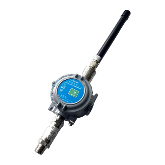
USER GUIDE FOR EX D APPROVED
SIGFOX PROCESS PRESSURE
SENSOR WSSFCEX-PPS
WSSFCEX-PPS -MN-EN-01
This document is applied for the following products
SKU
WSSFCEX-PPS
WSSFCEX-PPS-9-10
Item Code
WSSFCEX-PPS-8-10
WSSFCEX-PPS-G-1000
0. Configuration Check List
STEP 1: Select RC
1. Select RC zone
HW Ver.
1.2
SIGFOX GAGE PROCESS PRESSURE SENSOR, ATEX EXD APPROVAL ZONE 1/2, RANGE 0-10 BARG,
ACCURACY 0.5%, PROCESS CONNECTION 1/2" NPT-MALE, 316SS, TYPE AA BATTERY 1.5VDC, RC2-
RC3-RC4-RC5 ZONES
SIGFOX GAGE PROCESS PRESSURE SENSOR, ATEX EXD APPROVAL ZONE 1/2, RANGE 0-10 BARG,
ACCURACY 0.5%, PROCESS CONNECTION 1/2" NPT-MALE, 316SS, TYPE AA BATTERY 1.5VDC, RC1-
RC6-RC7 ZONES
SIGFOX GAGE PROCESS PRESSURE SENSOR, ATEX EXD APPROVAL ZONE 1/2, RANGE 0-1000
BARG, ACCURACY 0.5%, PROCESS CONNECTION 1/2"NPT-MALE, 316LSS, TYPE AA BATTERY
1.5VDC, RC1-RC2-RC3-RC4 ZONES
RC zones selection 1, 2, 4,... is RCZ1, RCZ2, RCZ4,... (refer to
6)
FW Ver.
1.2
SEP-2020
section
Advertisement
Table of Contents

Subscribe to Our Youtube Channel
Related Manuals for Sigfox WSSFCEX-PPS


Summary of Contents for Sigfox WSSFCEX-PPS
- Page 1 This document is applied for the following products WSSFCEX-PPS HW Ver. FW Ver. SIGFOX GAGE PROCESS PRESSURE SENSOR, ATEX EXD APPROVAL ZONE 1/2, RANGE 0-10 BARG, WSSFCEX-PPS-9-10 ACCURACY 0.5%, PROCESS CONNECTION 1/2" NPT-MALE, 316SS, TYPE AA BATTERY 1.5VDC, RC2- RC3-RC4-RC5 ZONES...
-
Page 2: Change Log
2. Introduction WSSFCEX-PPS is the Sigfox Integrated Process Pressure Sensor with Exd approval for installation in Zone 1, Zone 2 or Safe Zone, and it has different kinds of measurements, such as Gage/Absolute/Sealed Gage, range -1 .. + 700 bar, high accuracy, and stability. -
Page 3: Specification
Housing Cast aluminium, powder coated, IP66 Mounting wall mounting holes Product dimensions H100xW100xD80 (excluded antenna) Net weight 1.5 kgs Packaging dimension W160 x D150 x H250 mm Gross weight < 1.6 kgs 4. Dimensions 4.1 WSSFCEX-PPS with 0-10 barg version... -
Page 4: Operation Principle
Then during the operation, there are 03 cases of sending data to base station: 1. When the sensor sampling time interval is reached, the Sigfox node will read the data from Input or sensor and performing the calculation. After that it will check calculated value with alarm thresholds. If the calculated was out off the threshold values (Lo or Hi), called alarm, and the number of times of alarm did not pass the limit of number of alarms, then it will send data to Base station immediately;... -
Page 5: Led Meaning
POST- EVENT PRE-CONDITION ACTION LED STATUS BUZZER STATUS ACTIVITIES CONDITION Move Magnet Key to contact point of REED SWITCH. Back to previous FORCE_DATA Any state Blink SKY BLUE Beep 1 time See FW specs Buzzer beep 1 state time, move Magnet Key away. -
Page 6: Button Function
The RF transmit power will be automatically set as the max value as allowed by the Zone. Sigfox Radio Configuration (RC) defines the radio parameters in which the device shall operate: Sigfox operating frequencies, output power, spectrum access mechanism, throughput, coexistence with other radio technologies, etc. - Page 7 The Sigfox network globally works within the ranges from 862 to 928 MHz. But not all RCs require such a wide range of operation. Uplink center frequency (MHz) 868.130 902.200 920.800 Downlink center frequency (MHz) 869.525 905.200 922.300 Uplink data rate (bit/s)
- Page 8 Step 3: Click New → Select a group Step 4: Fill in the required information...
- Page 9 Note: Some of our products may not have end product certification in time, to add the product to Backend Sigfox please follow the steps below. Click on the text as shown below Check the box as shown below to register as a prototype...
- Page 10 5.5 Process of measurement When the sensor sampling time interval is reached, for example 2 minutes, the Sigfox node will wake up and switch ON the power supply to supply the energy to external sensor to start the measurement. Depends on the type and characteristic of external sensor, the sensor will take a certain time to finish the measurement.
-
Page 11: Configuration Parameters
DOWNLINK_TYPE Downlink type 0b0000 See Sigfox Downlink tab 5.7 Payload Data The following is the format of payload data will be sent to Sigfox server. Length is 6 bytes, it is future-proof for expansion to 12 bytes. 5.7.1 Payload Fields... - Page 12 8-bit unsigned integer Formula: (8-bit_Tentative +1)= real_tentative # Range: 1 to 256 TENTATIVE Tentative number Accuracy: 1 Example: 0b00000111 = 0x7=7=> 7+1 =>tentative # 8 5.7.2 Sigfox Uplink Frame Format Size (led blink WHITE) START_UP LATEST_SIGFOX_ Payload EVENT_ID HW_VERSION FW_VERSION DOWNLINK 10.0...
- Page 13 5.7.3 Payload for Downlink, length is 8 bytes. The Sigfox node is only able to receive max 04 downlinks a day, each downlink will be waiting in every 06 hours. User can set the down link data in Sigfox back-end system in advance, whenever the Sigfox node connected to base...
- Page 14 The downlink data can be any configuration parameter. Please pay attention when send downlink data. If there was a mistake in sending wrong data, it would cause the Sigfox node not working properly and user need to configure it by offline cable!!! Size...
- Page 15 NOTE: The Modbus configuration can be done in the first 60s after power up the Sigfox node. After 60s, if user can not finish the configuration, user need to reset the power of Sigfox node again, by removing battery in at least 15s.
- Page 16 Step 4: Plug the connector to the configuration port; Black Yellow on cable will go with Rx on sensor and vice versa. Step 5: Insert the battery;...
- Page 17 Step 6: Import the configuration file by importing the csv file: Go to MENU: FILE / Import New / => select the file with name CONFIGURATION TEMPLATE FILE FOR SIGFOX FW1.9.3.csv (in the link below). Then click Connect; CONFIGURATION TEMPLATE FILE FOR SIGFOX WSSFCEX-PPS.csv...
- Page 18 Code Code Range Default Format Property Comment Registers (DEC) (Hex) (Read) (Write) CURRENT_CONFIGURATION Read/Write 0: Send to Sigfox SERVER_CONFIG uint16 Read/Write Network 1: Send to Dongle RC zones selection RADIO_CONFIG 1, 2 ,4 is 1, 2, 4 uint16 Read/Write RCZ1,...
-
Page 19: Installation
To maximize the distance of transmission, the ideal condition is Line-of-sight (LOS) between the Sigfox sensor and Base station. In real life, there may be no LOS condition. However, the Sigfox sensor still communicate with Base station, but the distance will be reduced significantly. -
Page 20: Process Mounting
7.2 Process mounting WARNINGS: 1. Please make sure the fluid is suitable with the wetted materials of the sensor. Please refer sensor specification; 2. Please make sure the operating temperature and pressure is suitable with the sensor. Please refer sensor specification;... -
Page 21: Battery Installation
7.2.2 Remote mounting on wall or pole Make sure the wall or place of pole for mounting is not covered or affected by the surrounding metallic objects; Using the metal tubing and fittings for interconnection between process pipe and sensor process connector; The metal tubing and fitting materials, and size must be sizing properly to suit the process conditions;... - Page 22 Step 2: Carefully take out the front cover of the sensor Step 3: Insert the type AA battery, please take note the polarity of battery ATTENTION: REVERSED POLARITY OF BATTERIES IN 10 SECONDS CAN DAMAGE THE SENSOR CIRCUIT!!! Step 4: Turn the front cover of the sensor clockwise to close fully. NOTES: Using 2mm hex key to lock the cover to prevent the unattended opening.
-
Page 23: Troubleshooting
8. Troubleshooting Phenomena Reason Solutions Check that the battery is empty or not installed No power supply Node does not send RF to base correctly Configuration sending station periodically, LED does not Check the power supply cycle is incorrect blink Check the send cycle configuration The alarm configuration is...
Need help?
Do you have a question about the WSSFCEX-PPS and is the answer not in the manual?
Questions and answers