Table of Contents
Advertisement
Quick Links
Advertisement
Table of Contents

Related Manuals for Asus H610A-IM-A


Summary of Contents for Asus H610A-IM-A
- Page 1 H610A-IM-A...
- Page 2 Product warranty or service will not be extended if: (1) the product is repaired, modified or altered, unless such repair, modification of alteration is authorized in writing by ASUS; or (2) the serial number of the product is defaced or missing.
-
Page 3: Table Of Contents
Contents Chapter 1 Product overview Package contents................. 1-1 Features ..................1-1 Specifications ................1-2 Chapter 2 Motherboard information Before you proceed ..............2-1 Motherboard layout ..............2-2 Central Processing Unit (CPU) ........... 2-4 2.3.1 Installing the CPU ............2-5 2.3.2 CPU heatsink and fan assembly installation .... - Page 4 3.3.13 Onboard Devices Configuration ........3-12 3.3.14 Miscellaneous ............... 3-12 3.3.15 APM Configuration ............3-13 3.3.16 EzFlash ................. 3-13 3.3.17 Watchdog Timer ............3-13 Hardware Monitor menu ............3-14 Security menu ................3-14 Boot menu .................. 3-16 Exit menu ..................3-17 Appendix Notices .......................A-1 Service and Support .................A-5...
-
Page 5: Chapter 1 Product Overview
Chapter 1 Product overview Package contents Check your industrial motherboard package for the following items. 1 x ASUS H610A-IM-A Industrial Motherboard 1 x SATA 6.0 Gb/s cable 2 x M.2 screw package 1 x ASUS I/O Shield NOTE: If any of the above items is damaged or missing, contact your distributor or sales representative immediately. -
Page 6: Specifications
4 x USB 2.0 ports 2 x LAN (RJ45) ports 2 x COM ports (RS232/422/485) 2 x Audio jacks 4 x COM headers (RS232) Internal I/O connectors 1 x USB 2.0 header supports additional 2 USB 2.0 ports (continued on the next page) H610A-IM-A... - Page 7 1 x CPU Fan header (PWM mode) 2 x Chassis Fan headers (PWM mode) 1 x Chassis intrusion header 1 x Front Panel Audio header (AAFP) 1 x System Panel header 1 x Buzzer Onboard 1 x Clear CMOS header 1 x Speaker header 1 x COM Debug header Internal I/O...
-
Page 8: Chapter 2 Motherboard Information
Chapter 2 Motherboard information Before you proceed Take note of the following precautions before you install motherboard components or change any motherboard settings. CAUTION! • Unplug the power cord from the wall socket before touching any component. • Before handling components, use a grounded wrist strap or touch a safely grounded object or a metal object, such as the power supply case, to avoid damaging them due to static electricity. -
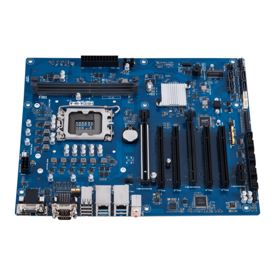
Page 9: Motherboard Layout
® PCI_1 I219V Intel ® I210AT Intel ® PCI_2 H610 128Mb BIOS PCIEX16(G3) Super BUZZER PCI_3 M.2(SOCKET3) 1083 PCIE SATA 3.0 X1 PCI_4 SATA6G_3 SATA6G_4 PCIEX1(G3) CHA_FAN1 GPIO_CON COM3 COM4 COM5 COM6 SATA6G_1 SATA6G_2 AAFP KBMS_CON SPEAKER CHASSIS F_PANEL H610A-IM-A... - Page 10 Connectors/Jumpers/Slots Page COM RING/+5V/+12V selection (COM1/2_SEL) 2-12 ATX Power connectors (24-pin ATXPWR, 2 x 4-pin EATX12V) 2-16 CPU and Chassis Fan headers (4-pin CPU_FAN, 4-pin CHA_FAN) 2-16 Intel LGA1700 CPU socket ® DDR4 U-DIMM slots USB 2.0 header (10-1pin USB914,) 2-17 TPM header (14-1 pin TPM) 2-17...
-
Page 11: Central Processing Unit (Cpu)
ASUS will shoulder the cost of repair only if the damage is shipment/transit-related. • Keep the cap after installing the motherboard. ASUS will process Return Merchandise Authorization (RMA) requests only if the motherboard comes with the cap on the LGA1700 socket. -
Page 12: Installing The Cpu
DO NOT install a CPU designed for LGA1155, LGA1156, LGA1151, and LGA1200 sockets on the LGA1700 socket. • ASUS will not cover damages resulting from incorrect CPU installation/ removal, incorrect CPU orientation/placement, or other damages resulting from negligence by the user. - Page 13 H610A-IM-A...
-
Page 14: Cpu Heatsink And Fan Assembly Installation
2.3.2 CPU heatsink and fan assembly installation CAUTION! Apply the Thermal Interface Material to the CPU heatsink and CPU before you install the heatsink and fan if necessary. To install the CPU heatsink and fan assembly Chapter 2: Motherboard information... - Page 15 Intel 600 series ® motherboard. • Additional holes for LGA1200 compatible cooling systems are also available on ASUS’ Intel 600 series motherboards, ® however, we still strongly advise consulting with your cooling system vendor or manufacturer on the...
-
Page 16: System Memory
System memory This motherboard comes with two Double Data Rate 4 (DDR4) Dual Inline Memory Module (DIMM) sockets. The figure below illustrates the location of the DDR4 DIMM sockets: LGA1700 Channel Sockets Channel A DIMM_A Channel B DIMM_B Installing a DIMM Chapter 2: Motherboard information... - Page 17 To remove a DIMM H610A-IM-A 2-10...
-
Page 18: Jumpers
Jumpers Clear RTC RAM (2-pin CLRTC) This header allows you to clear the CMOS RTC RAM data of the system setup information such as date, time, and system passwords. CLRTC PIN 1 Connector type HEADER 1x2p, 2.54mm pitch, S/T To erase the RTC RAM: Turn OFF the computer and unplug the power cord. - Page 19 COM Ring/+5V/+12V selection jumper (6-pin COM1/2_SEL) COM1_SEL COM2_SEL +12V (Default) Setting Pins +12V Ring (Default) AT/ATX mode selection (3-pin AT_ATX_SEL) AT_ATX_SEL ATX mode AT mode (Default) Pins 1-2 (Default) ATX mode AT mode HEADER 1x3p, 2.54mm pitch, S/T Connector type H610A-IM-A 2-12...
- Page 20 3-pin SMBDATA_SW SMBDATA_SW Eanble PCIe SMBus connection Disable PCIe SMBus connection (Default) Setting Pins Enable PCIe SMBus connection (Default) Disable PCIe SMBus connection 3-pin SMBCLK_SW SMBCLK_SW Eanble PCIe SMBus connection Disable PCIe SMBus connection (Default) Settings Pins Pins Enable PCIe SMBCLK connection (Default) 1-2 Disable PCIe SMBCLK connection Chapter 2: Motherboard information 2-13...
-
Page 21: Connectors
® connector, and is HDCP compliant allowing playback of HD DVD, Blu-ray, and other protected content. USB 3.2 Gen 2 (up to 10Gbps) ports. These 9-pin Universal Serial Bus (USB) ports are for USB 3.2 Gen 2 devices. H610A-IM-A 2-14... - Page 22 USB 3.2 Gen 1 (up to 5Gbps) ports. These 9-pin Universal Serial Bus (USB) ports are for USB 3.2 Gen 1 devices. 10. Microphone port (pink). This port connects to a microphone. Refer to the audio configuration table for the function of the audio ports in 2, 4, 5.1, or 7.1-channel configuration.
-
Page 23: Internal Connectors
WAFER HD 4p, 2.54mm pitch, S/T CAUTION: Do not forget to connect the fan cables to the fan headers. Insufficient air flow inside the system may damage the motherboard components. These are not jumpers! Do not place jumper caps on the fan headers! H610A-IM-A 2-16... - Page 24 USB 2.0 header (10-pin USB914) This header is for USB 2.0 ports. Connect a USB cable to the header. The USB header complies with USB 2.0 specification that supports up to 480 Mbps connection speed. USB914 USB_P9+ USB_P14+ USB_P9- USB_P14- USB+5V USB+5V PIN 1...
- Page 25 M.2 slot (SOCKET 3) This slot allows you to install an M.2 SSD module. M.2(SOCKET3) Connector type NGFF KEY-M 67P, 8.5H NOTES: • The M.2 SSD module is purchased separately. • This slot supports M Key and 2242/2260/2280 storage devices. H610A-IM-A 2-18...
- Page 26 System Panel header (10-1 pin F_PANEL) This header supports several chassis-mounted functions. +PWR_LED PWR_BTN F_PANEL PIN 1 +HDD_LED RESET Connector type HEADER 2x5p, K10, 2.54mm pitch • System power LED (2-pin +PWR_LED) This 2-pin header is for the system power LED. Connect the chassis power LED cable to this header.
- Page 27 The chassis intrusion sensor or switch sends a low-level signal to this connector when a chassis component is installed. The signal is then generated as a chassis intrusion event. CHASSIS PIN 1 HEADER 4p, K2, 2.54mm pitch Connector type H610A-IM-A 2-20...
- Page 28 10. SATA 6.0Gb/s ports (7-pin SATA6G_1-4) These ports connect to SATA 6.0 Gb/s hard disk drives or an optical drive via SATA 6.0 Gb/s signal cables. SATA6G_3 SATA6G_4 SATA6G_1 SATA6G_2 SATA CON 7P S/T Connector type 11. General Purpose Input/Output header (GPIO_CON) This header is for a general purpose input/output module which allows you to customize the digital signal input/output.
- Page 29 The LPT (Line Printing Terminal) header supports devices such as a printer. LPT is standardized as IEEE 1284, which is the parallel port interface on IBM PC-compatible computers. PIN 1 Connector type HEADER 2x13p, K26, 2.54mm pitch, S/T H610A-IM-A 2-22...
- Page 30 14. COM Port headers (10-pin COM3 - COM6) These headers are for serial (COM) ports. Connect the serial port cables to these headers, then install the module to a slot opening at the back of the system chassis. COM3 COM4 COM5 PIN 1 COM6...
- Page 31 • If you want to connect a high-definition front panel audio module to this header, set the HD Audio Controller item in the BIOS setup to [Enabled]. H610A-IM-A 2-24...
- Page 32 16. COM Debug header (5-1 pin COM_DEBUG) This header allows connection to a COM Debug card. COM_DEBUG PIN 1 Connector type HEADER 2x3p, K3, 2.54 mm pitch, S/T NOTE: The COM Debug Card is purchased separately. Chapter 2: Motherboard information 2-25...
-
Page 33: Chapter 3 Bios Setup
Always shut down the system properly from the operating system. IMPORTANT: • Visit the ASUS website at www.asus.com to download the latest BIOS file for this motherboard. • The default BIOS settings for this motherboard apply to most working conditions and ensures optimal performance. -
Page 34: Bios Menu Screen
The Main menu provides you an overview of the basic system information, and allows you to set the system date, time, language, and security settings. 3.2.1 System Date [Day MM/DD/YYYY] Allows you to set the system date. 3.2.2 System Time [HH:MM:SS] Allows you to set the system time. H610A-IM-A... -
Page 35: Advanced Menu
Advanced menu The Advanced menu items allow you to change the settings for the CPU and other system devices. Be cautious when changing the settings of the Advanced menu items. Incorrect field values can cause the system to malfunction. 3.3.1 PCH-FW Configuration TPM Device Selection This item allows you to select the TPM device. -
Page 36: Graphics Configuration
Allows you to select a primary display from IGFX, PEG and PCI graphical devices. Primary Display Allows you to select which of the IGFX/PEG/PCI Graphics device should be the Primary Display. Configuration options: [Auto] [IGFX] [PEG Slot] [PCH PCI] Internal Graphics [Auto] Keep IGFX enabled base on the setup options. H610A-IM-A... -
Page 37: Pci Express Configuration
[Disabled] Disables internal graphics. [Enabled] Enables internal graphics. RC6 (Render Standby) Allows you to enable or disable render standby support. Configuration options: [Disabled] [Enabled] 3.3.5 PCI Express Configuration Allows you to select a PEG or PCI graphical device. PCIEX16 (G5) Slot PCIEx16 (G5) Slot This item allows you to enable or disable the PCIEX16 (G5) slot. - Page 38 Configures the speed of PCIEx1 (G3) slot. Configuration options: [Auto] [Gen1] [Gen2] [Gen3] Detect Timeout Allows you to set the time (milliseconds) of waiting for link to exit Detect state for enabled ports before assuming there is no device and potentially disabling H610A-IM-A...
-
Page 39: Csm Configuration
the port. Use the <+> and <-> keys to adjust the value or input the desired value. Hot Plug These items allow you to enable/disable PCIEX1 (G3) slot Hot Plug support. Configuration options: [Disabled] [Enabled] Detect Non-Compliance Device Allows you to enable or disable the detection function of non-compliance PCI Express device. - Page 40 The following items appear only when you set Parallel Port to [Enabled]. Device Mode Allows you to select the Parallel Port mode. Configuration options: [STD Printer Mode] [SPP Mode] [EPP-1.9 and SPP Mode] [EPP-1.7 and SPP Mode] [ECP Mode] [ECP and EPP 1.9 Mode] [ECP and EPP 1.7 Mode] H610A-IM-A...
-
Page 41: Serial Console Redirection
3.3.8 Serial Console Redirection COM1~COM6 Console Redirection Configuration options: Allows you enable or disable the console redirection feature. [Enabled] [Disabled] Console Redirection Settings The settings specify how the host computer and the remote computer (which the user is using) will exchange data. Both computers should have the same or compatible settings. -
Page 42: Sata Configuration
SATA6G_1/2/3/4 Allow you to enable/disable the SATA6G_1/2/3/4 port. Configuration options: [Disabled] [Enabled] Hot Plug Allow you to enable/disable the hot plug function. Configuration options: [Disabled] [Enabled] H610A-IM-A 3-10... -
Page 43: Network Stack Configuration
3.3.10 Network Stack Configuration Network Stack This item allows user to disable or enable the UEFI network stack. Configuration options: [Disabled] [Enabled] The following two items appear only when you set the previous item to [Enabled]. Ipv4 PXE Support This item allows user to disable or enable the Ipv4 PXE Boot support. Configuration options: [Disabled] [Enabled] Ipv6 PXE Support This item allows user to disable or enable the Ipv6 PXE Boot support. -
Page 44: Nvme Configuration
DMI Link. Configuration options: [Disabled] [Auto] [ASPM L0s] [ASPM L1] [ASPM L0sL1] PCI Express Configuration DMI Link ASPM Control This item allows you to control the Active State Power Management of the DMI Link. Configuration options: [Disabled] [L1] [Auto] H610A-IM-A 3-12... -
Page 45: Apm Configuration
3.3.15 APM Configuration ErP Ready Allows you to switch off some power at S5 to get the system ready for ErP requirement. When set to [Enabled], all other PME options will be switched off. Configuration options: [Disabled] [Enabled] Restore AC Power Loss [S5 State] The system goes into off state after an AC power loss. -
Page 46: Hardware Monitor Menu
This menu allows a new password to be created or a current password to be changed. The menu also enables or disables the Secure Boot state and lets the user configure the System Mode state. Administrator Password If you have set an administrator password, we recommend that you enter the H610A-IM-A 3-14... - Page 47 administrator password for accessing the system. To set an administrator password: Select the Administrator Password item and press <Enter>. From the Create New Password box, key in a password, then press <Enter>. Confirm the password when prompted. To change an administrator password: Select the Administrator Password item and press <Enter>.
-
Page 48: Boot Menu
Allows you to select the boot mode. Configuration options: [LEGACY] [UEFI] FIXED BOOT ORDER Priorities Boot Option #1~#5 This item allows you to set the system boot order. Configuration options: [Hard Disk] [NVME] [CD/DVD] [USB Device] [Network] [Disabled] H610A-IM-A 3-16... -
Page 49: Exit Menu
Exit menu The Exit menu items allow you to save or discard your changes to the BIOS items. Save Changes & Exit This option allows you to save your changes and exit the Setup program. When you select this option or if you press <Esc>, a confirmation window appears. Select Yes to save changes and exit. -
Page 50: Appendix
Appendix Notices FCC Compliance Information Responsible Party: Asus Computer International Address: 48720 Kato Rd., Fremont, CA 94538, USA Phone / Fax No: (510)739-3777 / (510)608-4555 This device complies with part 15 of the FCC Rules. Operation is subject to the following two conditions: (1) This device may not cause harmful interference, and (2) this device must accept any interference received, including interference that may cause undesired operation. - Page 51 CAN ICES-003(B)/NMB-003(B) VCCI: Japan Compliance Statement Class B ITE KC: Korea Warning Statement HDMI Compliance Statement The terms HDMI, HDMI High-Definition Multimedia Interface, and the HDMI Logo are trademarks or registered trademarks of HDMI Licensing Administrator, Inc. H610A-IM-A...
- Page 52 ASUS Recycling/Takeback Services ASUS recycling and takeback programs come from our commitment to the highest standards for protecting our environment. We believe in providing solutions for you to be able to responsibly recycle our products, batteries, other components as well as the packaging materials.
- Page 53 доступний на: www.asus.com/support Cijeli tekst EU izjave o sukladnosti dostupan je na: www.asus.com/support Türkçe AsusTek Computer Inc., bu aygıtın temel gereksinimlerle ve ilişkili Čeština Společnost ASUSTeK Computer Inc. tímto prohlašuje, že toto Yönergelerin diğer ilgili koşullarıyla uyumlu olduğunu beyan eder.
-
Page 54: Service And Support
Service and Support Visit our multi-language website at https://www.asus.com/support/ Appendix...
Need help?
Do you have a question about the H610A-IM-A and is the answer not in the manual?
Questions and answers