Table of Contents
Advertisement
Quick Links
Advertisement
Table of Contents

Related Manuals for Wallgate WEX300


Summary of Contents for Wallgate WEX300
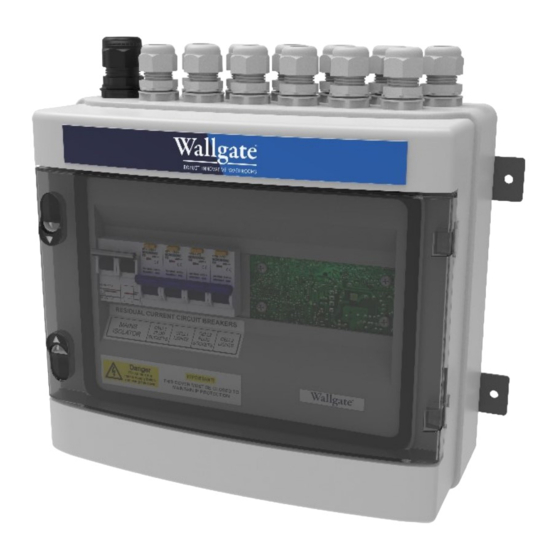
- Page 1 Product Manual WEX300 Electrical Management Controller. Original Instructions...
- Page 2 • If the supply cord is damaged, it must be replaced by Wallgate, its service agents or similarly qualified persons in order to avoid hazard.
-
Page 3: Table Of Contents
WEX 300 Electrical Management. Table of Contents 1. Disclaimer & Copyright Notice ....................4 2. Conventions ........................... 4 2.1 Warning ..........................4 2.2 Note ............................ 5 2.3 Numbered procedures ....................... 5 2.4 Bullet lists ..........................5 2.5 Tick Bullet lists ........................5 2.6 Menu items ......................... -
Page 4: Disclaimer & Copyright Notice
In any event, and without prejudice to any warranties in Wallgate Limited’s terms and conditions of sale, Wallgate Limited’s liability for all damages and losses (including negligence) shall not in any circumstances exceed the amount paid by the customer for the unit. -
Page 5: Note
WEX 300 Electrical Management. 2.2 Note A note with amber text on a white background is used to draw your attention to important and useful information. NOTE: This is a note. 2.3 Numbered procedures Steps in procedures are numbered, starting from 1. This is step 1. -
Page 6: Advice On Attaching The Unit
WEX 300 Electrical Management. 3.2 Advice on attaching the unit • Attached the unit to a vertical surface that is able to support the weight of the unit. • Attach the unit in dry surroundings above pipes carrying water, away from any possible plumbing leaks. -
Page 7: Product Specification
2 x C4 RCBO for mains socket protection 2 x C2 RCBO for lighting protection NOTE: The WEX300 can be specified with MAX 10A per Breaker, please contact Wallgate sales for details. 4 x power monitoring channels (optional) 4 x zero crossing detection for mains failure detection 5.6 Communications... -
Page 8: Connections
WEX 300 Electrical Management. 6 Connections The WEX300 is connected to the peripherals it is controlling through 13 glands located on the top side of the housing. One M25 gland for the incoming power and 12 M20 glands for the socket and lighting circuits. Below in Figure 1 is an overview of the connections to the WEX300 unit. - Page 9 Power is fed into unit through circuit breaker CB1 in Figure 2 below. A common Live bus is fed through RCBO 1, 2, 3 and 4. The neutrals are monitored by the power monitoring circuitry on PCB000378 (WEX300-MTR) through shunts PM1, PM2, PM3 and PM4 on the neutral lines of the RCBOs.
- Page 10 WEX 300 Electrical Management. Figure 3 Wiring for Socket and Light Circuits With reference to Figure 3 above, the wiring is as follows. Neutral is on the left and Live on the Right of each two-way connector. A. Feed in for Socket A circuits from RCBO1 B.
-
Page 11: System Description
7 System Description 7.1 Digital Inputs, Outputs and LEDs The WEX300 has 20 digital inputs which can be setup in the configuration on the WDC 100\200 NX. These inputs are 3.5mm stereo jack plugs to connect to push buttons, optional remote controls and lighting switches and are located on the bottom of the WEX300 housing. -
Page 12: Relay Outputs
Figure 5 Relay Outputs Sections 7.3 Communications The WEX300 is a slave device and is controlled by a WDC100\200 via CANbus. The CAN is connected via a 4way RJ11 connector. Within the WEX300 there are three boards which also need to communicate, the control board, the metering board, and the relay board, this is done via RS-232. -
Page 13: Mains Voltage Devices
WEX 300 Electrical Management. 7.4 Mains Voltage Devices The WEX300 is a mains connected device and therefore caution must be taken when wiring. Below in FIGURE is the section of the relay board which is Live, elsewhere below the indicated zone is a maximum voltage of 12V DC. - Page 14 WEX 300 Electrical Management. Revision 2...
-
Page 15: Operation
WEX 300 Electrical Management. 10 Operation Use the main isolation switch provided by the installer to switch the unit on or off. The main isolation switch is located near to the electronic control box. If unit is faulty, switch off the control unit until the fault is repaired by a qualified engineer. WARNING! Risk of electric shock, serious injury and death. - Page 16 Wallgate Ltd. Crow Lane, Wilton, Salisbury, Wiltshire, SP2 0HB, England tel: +44 (0) 1722 744594 fax: +44 (0) 1722 742096 email: service@wallgate.com web: www.wallgate.com...
Need help?
Do you have a question about the WEX300 and is the answer not in the manual?
Questions and answers