Table of Contents
Advertisement
Advertisement
Table of Contents

Related Manuals for Wallgate WDC200


Summary of Contents for Wallgate WDC200
- Page 1 Product Manual WDC200 Electronic Control For Basins/Baths, Showers and WCs...
- Page 2 Product Manual WDC200 Electronic Control AS 1172 RCM Mark Certificate No Australia 23167 Revision 18...
-
Page 3: Table Of Contents
5.16. Auto-Run ......................... 19 5.17. Technical Specifications ....................19 6. User and Maintenance Instructions ..................20 6.1. Operation .......................... 20 6.2. Maintenance ........................22 7. WDC200 Menu Settings ....................... 22 8. Related Documentation ....................... 30 9. Model Variations ........................31 Revision 18... -
Page 4: Disclaimer & Copyright Notice
Every effort has been made to supply information within this manual which is correct. Wallgate Limited will not be liable for any damage or loss that arises if the person installing, operating or maintaining the unit has not read or not complied with the manual In any event, and without prejudice to any warranties in Wallgate Limited’s terms and... -
Page 5: Conventions
A warning with red text on a white background is used to give information about hazards that can cause injury or death. Read and understand the warnings before you install and commission the WDC200. Failure to heed these warnings can have serious consequences. -
Page 6: Glossary
Data Logging Activations of the Hygiene Purge function detailed below are logged in memory and then using additional software the logs can be downloaded from the WDC200 and imported into a spreadsheet report. Dual Flush This option is used when both full and half flush options must be provided, using either one or two inputs. - Page 7 The RJ-45 connectors are used to connect the WDC unit to a PC or laptop. Real Time Clock. This is a 24 hour 7 day clock used by the WDC200 for program features such as Time Slots and Hygiene Purge. System Test...
-
Page 8: Product Summary
*The WDC200 can be set to operate with a bath instead of a basin if required. This would entail the installer or client adjusting water run times to 180 seconds for hot and cold, or as preferred. -
Page 9: Installation And Commissioning
Product Manual WDC200 Electronic Control 5. Installation and Commissioning 5.1. Package Contents Before you begin the installation, make sure that you have the following items: ✓ 1 WDC200 Electronic control unit ✓ 1 Product manual. 5.2. Site Preparation 5.2.1. Advice on attaching the unit •... -
Page 10: Attach The Controller Unit
Product Manual WDC200 Electronic Control 5.3 Attach the Controller Unit To attach the control unit to the wall, do the following: Mark the attachment points for the control unit on the wall. Make sure the cables from the solenoid valves and Piezo touch buttons are of sufficient length to reach the control unit. -
Page 11: Connect The Input And Output Cables
The control unit has input and output sockets in the lower panel of the unit. Refer to Figure 2 for the illustration of the lower panel. Figure 2. Connectors in the WDC200 control unit Table 3. Legend for Figure 2... - Page 12 Product Manual WDC200 Electronic Control Item number Description Function Input from WC Flush User input (Piezo touch button or Piezo touch button / IR sensor) for WC Flush Room 2 sensor Input from Shower Piezo User input (Piezo touch button or...
-
Page 13: Connect The 3-Pin Output Connector
Product Manual WDC200 Electronic Control 5.5. Connect the 3-pin output connector To connect the 3-pin type connector to the socket in the unit, carry out these steps: The cable plug has a raised key that must be aligned with the slot in the socket, for it to fit correctly. -
Page 14: Commission The Unit
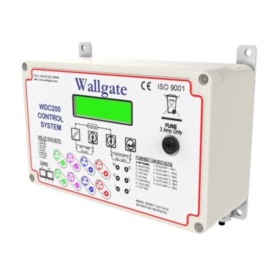
Complete electrical testing of the installation. 5.8. Commission the Unit All the switches and the menu display is located on the front panel of the WDC200 control unit. Refer to figure 3 below for an illustration of the WDC200 front panel. -
Page 15: Lockout Function
To stop the cycle, switch off the electrical supply to the electronic control unit. Correct any problems such as blockages before you run the purge cycle again. The control unit has various function settings that can be enabled or disabled. The settings are given in section 7, WDC200 Menu Settings. 5.10. Lockout function The Lockout function restricts the number of usages for the basin/bath, shower and WC. -
Page 16: Piezo Touch Button And Infrared Sensor Controls
Product Manual WDC200 Electronic Control then this can be adjusted by amending the Lockout Mode setting from 1 to 2, see section 7 for menu list. Default settings are as follows. These can be reconfigured as required. • 1 hour for basin/bath and shower. -
Page 17: System Test Function
Product Manual WDC200 Electronic Control To test the operation of the piezo and infrared sensors: Operate each touch button or sensor and observe that they work correctly. The hot and cold basin valves are set to open for 10 seconds each. -
Page 18: Product Time Slots
Data logging records the events of the hygiene purge operations. The data log records can then be downloaded from the WDC200 to a PC or laptop. The download data is in the form of a csv file. Additional software is required from Wallgate to perform the download and create data log reports. -
Page 19: Auto-Run
Product Manual WDC200 Electronic Control 5.16. Auto-Run The Auto-Run function allows any output to automatically open at a set time every day. There are 48 half hourly time activations settings available for each output. Refer to section 7 to view the available time settings. When an output operates at the set time, it is ON for the preset cycle run time as set in “Cell Water Settings”... -
Page 20: User And Maintenance Instructions
6. User and Maintenance Instructions The electronic control unit has been designed and manufactured from good quality materials. If these instructions are followed, the unit will give reliable, efficient service. If you need any further information or advice, please contact Wallgate customer services. 6.1. - Page 21 Product Manual WDC200 Electronic Control Table 5. Important settings Setting Name Default State Description Exclusivity Disabled This prevents more than one outlet being operated at a time. Water Lockouts Disabled See Table 6 on page 25 for more information on this setting.
-
Page 22: Maintenance
Any service or repair work must be carried out by a qualified engineer. During the warranty period, the service or repair must only be done by a Wallgate engineer or appointed service agent. Refer to the Wallgate terms and conditions for warranty information. - Page 23 Product Manual WDC200 Electronic Control Table 6. WDC200 Menu Settings Available Default Main Menu Item Sub Menu 1 Sub Menu 2 Options Value Firmware version number appears. Use ↓ key to view the main menu. System Settings Management Start the System...
- Page 24 Product Manual WDC200 Electronic Control Available Default Main Menu Item Sub Menu 1 Sub Menu 2 Options Value Cell 1 Water Settings Basin cold outlet run Basin Cold Cycle 1 to 999 Seconds 10 Seconds time Time Basin hot outlet run...
- Page 25 Product Manual WDC200 Electronic Control Available Default Main Menu Item Sub Menu 1 Sub Menu 2 Options Value Cell 2 Water Settings Basin cold outlet run Basin Cold Cycle 1 to 999 Seconds 10 Seconds time Time Basin hot outlet run...
- Page 26 Product Manual WDC200 Electronic Control Available Default Main Menu Item Sub Menu 1 Sub Menu 2 Options Value Cell 1 Time Slots Specify the timings for Time Slot 1 Start 00:00 to 23:00 00:00 4 Basin 1 Time Slots. Time Slot 1 End...
- Page 27 Product Manual WDC200 Electronic Control Available Default Main Menu Item Sub Menu 1 Sub Menu 2 Options Value Cell 2 Time Slots Specify the timings for Time Slot 1 Start 00:00 to 23:00 00:00 4 Basin 2 Time Slots. Time Slot 1 End...
- Page 28 Product Manual WDC200 Electronic Control Available Default Main Menu Item Sub Menu 1 Sub Menu 2 Options Value Cell 1 Hygiene Settings Specify the period for Basin Inactivity Off or 1 to 100 Days basin inactivity. Period Specify the period for...
- Page 29 Product Manual WDC200 Electronic Control Auto Run default settings: Main Menu Item: Auto-Run Cycle Water Outlets Room 1 Room 2 3 – 4 – 7 – TIME 1 - WC 2 - SHWR 5 - WC 6 - SHWR 8 - BASIN...
-
Page 30: Related Documentation
Product Manual WDC200 Electronic Control Main Menu Item: Auto-Run Cycle Water Outlets Room 1 Room 2 3 – 4 – 7 – TIME 1 - WC 2 - SHWR 5 - WC 6 - SHWR 8 - BASIN BASIN BASIN... -
Page 31: Model Variations
9.2. WDC200-2 The WD200-2 is a standard WDC200 with two setting changes to allow it to operate a CIST21-ELEC. The CIST21-ELEC is a low-level cistern, refer to Wallgate website for details (www.wallgate.com). The settings refer to the air pump operation time. - Page 32 9.3. WDC200-3 The WD200-3 is a standard WDC200 with eight setting changes to allow it to operate a PSHD23. The PSHD23 is an extremely safe in-cell hand wash solution used in police holding cells, refer to Wallgate website for details (www.wallgate.com). The settings refer to the water run time on the unit.
- Page 33 Wallgate Ltd. Crow Lane, Wilton, Salisbury, Wiltshire, SP2 0HB, England tel: +44 (0) 1722 744594 fax: +44 (0) 1722 742096 email: service@wallgate.com web: www.wallgate.com...
Need help?
Do you have a question about the WDC200 and is the answer not in the manual?
Questions and answers