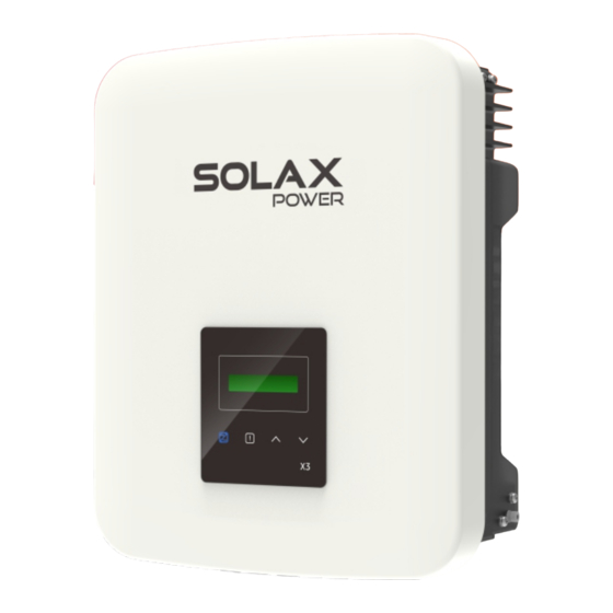
SolaX Power X3-MIC G2 Series Quick Installation Manual
3 kw-15 kw
Hide thumbs
Also See for X3-MIC G2 Series:
- User manual (109 pages) ,
- Installation manual (26 pages) ,
- Installation manual (76 pages)
Advertisement
X3-MIC G2 Series 3 kW-15 kW
Packing List
Expansion bolt X 3
Round washer X 3
Inverter X 1
Self tapping screw X 3
AC connector X 1
Waterproof connector
Earth terminal X 1
with RJ45 X 1
Meter (Optional)
DC pin contact X 4/6
DC connector X 4/6
WiFi dongle X 1
LAN dongle(Optional)
Documents
2*positive, 2*negative for 3 kW-8 kW and 10 kW(input A: one string)
3*positive, 3*negative for 12 kW-15 kW and 10 kW(input A: two strings)
Note: Please refer to the appropriate instruction manual for the
usage of WiFi and LAN dongle.
Inverter Installation
- Unscrew the bracket from the back of
- And mark the position(223 mm*30 mm)
the inverter.
of three holes.
- Insert the expansion bolts.
- Screw the self-tappingscrews.
PV Connection
cable size: 4 mm
7 mm
strip length
positive DC
cable
pin contact
clamp contact
negative DC
cable
pin contact
(torque:1.2±0.1 N·m)
clamp contact
×
+
-
+
-
PV array
- Drill holes with φ10 drill.
- Depth: at least 60 mm.
- Match the inverter with the bracket.
- Screw the cross recessed screw on the
right side.
torque: 0.8±0.1 N·m
6
- Align the PV connectors.
male plug
nut
tighten nut
female plug
nut
tighten nut
+
+
PV1
Note!
-
The PV connection mode in this box
+
is
not allowed!
PV2
-
-
Inverter
Advertisement
Table of Contents

Summary of Contents for SolaX Power X3-MIC G2 Series
- Page 1 - Drill holes with φ10 drill. the inverter. of three holes. - Depth: at least 60 mm. X3-MIC G2 Series 3 kW-15 kW - Insert the expansion bolts. - Screw the self-tappingscrews. - Match the inverter with the bracket. - Screw the cross recessed screw on the right side.
- Page 2 AC Connection WiFi Connection Ⅵ Select appropriate cable according to the power range as 1. Slide the cable nut and back shell onto the cable. recommended in “Table: Cable and Micro-breaker 2. Insert the stripped end of the ve wires into the appropriate holes of the recommended”...


Need help?
Do you have a question about the X3-MIC G2 Series and is the answer not in the manual?
Questions and answers