
Subscribe to Our Youtube Channel
Related Manuals for TEKNIX TKG104BL


Summary of Contents for TEKNIX TKG104BL
- Page 1 User manual Teknix Gas & Electrical 100 cm Range Cooker TKG104BL / TKDF104BL User manual Teknix Support 01759 487823...
- Page 2 Dear User, Our objective is to make this product provide you with the best output which is manufactured in our modern facilities in a careful working environment, in compliance with total quality concept. Therefore, we suggest you to read the user manual carefully before using the product and, keep it permanently at your disposal.
-
Page 3: Table Of Contents
CONTENTS Important Warnings Introduction Of The Appliance Important Warnings Electrical Wiring Scheme Gas Mark Table Gas Hose Passage Way Installation Of Your Oven Technical Features Of Your Oven Injector, Gas Flow And Power Table Reduced Gas Flow Rate Setting For Hob Taps Reduced Flame Gas Cock Adjustment Removal Of The Cathedral Burner Description Of Oven... -
Page 4: Important Warnings
IMPORTANT WARNINGS 1.WARNING: To avoid electrocution, ensure that the electrical circuit of the product is open before replacing the lamp. 2.WARNING:Before touching the connection terminals, all supply circuit should be disconnected. 3.WARNING:While operating the grill, the reachable sections can be hot. Keep the children away. 4.WARNING:Any inadvertent cooking made with fats and oils can be dangerous and cause fire. - Page 5 11.Using a gas hob will release humidity and combus- tion products in the room where it resides. Especially during when the appliance in use, ensure that the kitch- en is well ventilated and retain the natural ventilation holes or install a mechanical ventilation system. (Hood on top of the oven) Sustained usage of the appliance may require additional ventilation.
- Page 6 18.“Do not operate the system for more that 15 seconds. If the burner does not ignite at the end of 15 seconds stop the operation of the system and open the section door and/or wait for at least 1 minute before igniting the burner.
-
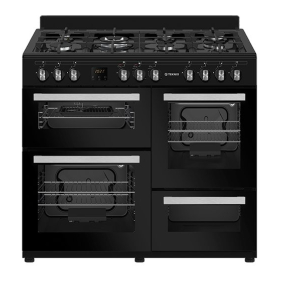
Page 7: Introduction Of The Appliance
INTRODUCTION OF THE APPLIANCE 1. Burner Plate 5. Splash Back* 2. Control Panel 6. RHS Oven 3. LHS Grill 7. Lower Part 4. LHS Main Oven 1. Auxiliary Burner 9. Normal Burner 5. LHS Gril 2. Rapid Burner 10. Auxiliary Burner 6. -
Page 8: Important Warnings
IMPORTANT WARNINGS Electrical Connection and Security 1. Your oven requires 26 Ampere fuse according to the appliance’s power. If necessary, installation by a qualified electrician is recommended. 2.Your oven is adjusted in compliance with 220-240V AC 50/60Hz. electric supply. If the mains are different from this specified value, contact your authorized service. -
Page 9: Electrical Wiring Scheme
6. If you make a connection with a flexible metal hose, locate a seal between the main gas pipes. 7. The inner diameter of the flexible hose, which the butane hose nozzle is connected, should be 6 mm for the house-type gas tubes. The inner diameter of the flexible hose, which the natural hose nozzle is connected, should be 15 mm.The hose should tightly be fitted to the hose nozzle by squeezing with a clamp. -
Page 10: Gas Mark Table
GAS MARK TABLE Gas Mark Fahrenheit Celsius Description Cool Very Moderate Moderate Moderately Hot Very Hot GAS HOSE PASSAGE WAY 1. Connect the appliance to the gas piping tap in shortest possible route and in a way that ensure no gas leakage will occur. 2. -
Page 11: Installation Of Your Oven
INSTALLATION OF YOUR OVEN 65mm min. 65mm min. Chain Lashing Illustration Before using the appliance, in order to ensure safe use, be sure to fix the appliance to the wall using thechain and hooked screw supplied. Ensure that the hook is screwed into the wall securely. -
Page 12: Technical Features Of Your Oven
TECHNICAL FEATURES OF YOUR OVEN Outer width 1000mm Outer depth 600mm Outer height 900mm Lamp power 15-25W Main Oven Grill Oven Top RHS Botton RHS Bottom heating element 1200W 1000W 600W Top heating element 1000W 800W 500W Turbo heating element 1800W 1800W Grill heating element... -
Page 13: Injector, Gas Flow And Power Table
RANGE COOKER INJECTOR, GAS FLOW And POWER TABLE G20,20 mbar G20,25 mbar BURNER G25,25 mbar SPECIFICATIONS Gas Natural Gas Natural Injector 1,40 1,28 Gas Flow 0,333 m³/h 0,333 m³/h Burner Power 3,50 3,50 Injector 1,15 1,10 Rapid Gas Flow 0,276 m³/h 0,276 m³/h... - Page 14 RANGE COOKER INJECTOR, GAS FLOW And POWER TABLE G30,28-30 mbar G30,50 mbar G30,37 mbar BURNER G31,37 mbar SPECIFICATIONS Injector 0,96 0,76 0,96 Gas Flow Burner Power 3,50 3,50 3,50 Injector 0,85 0,75 0,85 Rapid Gas Flow Burner Power 2,90 2,90 2,90 Injector 0,65...
-
Page 15: Reduced Gas Flow Rate Setting For Hob Taps
REDUCED GAS FLOW RATE SETTING FOR HOB TAPS 1. Ignite the burner that is to be adjustment and turn the knob to the reduced position. 2. Remove the knob from the gas tap. 3. Use an appropriately sized screwdriver to adjust the flow rate adjustment screw. -
Page 16: Removal Of The Cathedral Burner
REMOVAL OF THE CATHEDRAL BURNER The burner protection sheet is fixed with two screws. As shown in Figure 8, use a screwdriver to remove it. As shown in Figure 9, press the spring clip in the direction of the arrow to remove the burner from the slot. -
Page 17: Using The Burner Groups
USING THE BURNER GROUPS Closed Fully open Half open 2. If your oven has ignition system from push button switch please press and turn gas valve open position and same time press ignition button. 3. Our gas ovens top and bottom burner working system is one by one. When you want use your preference burner, before you must make press the tap knob and wait nearly 5-10 second. - Page 18 Pot Diameter WOK Burner 26-32cm Big Burner 22-26cm Normal Burner 18-22cm Small Burner 12-18cm False False False True Gas Connection and Safety 1. For LPG (cylinder) connection, affix metal clamp on the hose coming from LPG Main Gas Pipe cylinder. Affix an edge of the hose on hose inlet connector behind the appliance by Gasket pushing to end through heating the hose...
- Page 19 United Kingdom Type Gas Connection: 1. Gasket 2. Adapter c, __ _ 3. Gas (safety) hose 4. Valve with 90° outlet 5. Connection piece 6. Gas supply pipe WARNING: The gas hose must not be clamped, bent ar trapped or come into contact with hat parts of the product.
- Page 20 Using The Hobs 1. Auxiliary Burner 2. Normal Burner 3. Rapid Burner 4. Wok Burner Large flame symbol indicates the highest cooking power and small flame symbol indicates the lowest cooking power. In turned off position (top), gas is not supplied to the burners. Gas Breaking Safety Appliance Gas shut off safety Against putting out to be taken place as...
- Page 21 Using Ceramic Plates* The hob control knobs are used for operating the plates. To obtain the desired cooking power, turn the hob control knobs to the corresponding level. LEVEL LEVEL LEVEL LEVEL LEVEL LEVEL LEVEL LEVEL LEVEL MAX. 1000 1000 1000 1000 1000...
-
Page 22: Using Oven Section
Griddle* Ensure the griddle placed to pins on burner plate. Griddle becomes very hot while it is in use. Keep children away from the oven. Used to cook your food directly. Warning: Place the griddle Figure 17 only onto marked area. 1. - Page 23 Rack Positions (for models with wire shelf) It is important to place the wire shelf onto the side rack correctly. Wire shelf Rack 4 must be inserted between the side racks Rack 3 as illustrated in the figure. Do not let the Rack 2 wire shelf stand against the rear wall of Rack 1...
- Page 24 Catalytic Walls* Catalytic walls are located on the left and the right side of cavity under the guides. Catalytic walls banish the bad smell and obtain the best performance from the cooker. Catalytic walls also absorb oil residue and clean your oven while it’s operating.
-
Page 25: Cooking Time Table
COOKING TIME TABLE WARNING: Oven must be preheated for 7-10 minutes before placing the food in it. Oven Rack Cooking Temperature Cooking Foods Cavity Position Function (°C) Duration (min.) Cookie Left Bottom - Top Right Static-Turbo 170-180 30-35 Pizza Left Bottom Turbo Fan 200-240 20-25... -
Page 26: Timer Operation
TIMER OPERATION TKG104BL Clock Icon Minute Minder Icon TIME OF DAY ADJUSTMENT Press to the “ ” button. The “ ” icon between the hours and minutes will start to flash. Using the “ ” and “ ” buttons, you can adjust the current time of day. - Page 27 TIMER OPERATION TKDF104BL Is an electronic timer, which enables you to get the food ready to serve at the desired time. The only thing to be done is to program the cooking time and ready time. It can also be used as an alarm clock, where you just give in the amount of time after which it should remind you by a buzzer tone.
- Page 28 Note: Unless the ‘+’ or ‘–’ buttons are pushed along 5 seconds, time of the adjustment mode will be end up automatically. If you want to finish time of the adjustment mode rapidly, you should press ‘+’ and ‘–’ buttons simultaneously. ADJUSTING THE BUZZER ALARM With this feature, you can program after how much elapsed time you should be warned by a buzzer sound.
- Page 29 Now, you have programmed your oven to cook the food for 2 hours and 15 minutes. Please do not forget the function and/or the temperature knobs of your oven to appropriate positions. 4.After a few seconds, the screen will indicate that cooking has started and show the current time of Note: You may cancel the automatic cooking mode any time by entering ‘M’...
- Page 30 When automatic cooking is completed, a buzzer alarm is heard and will sound, if not stopped, for 7 minutes. 1.Switch OFF the oven 2.Reset the timer Note: Your oven will be inoperative until you reset In the example shown, cooking time has been programmed first; the ready time was calculated automatically and was edited by us.
-
Page 31: Cleaning And Maintenance Of The Oven's Door
CLEANING AND MAINTENANCE OF THE OVEN’S DOOR Drop-Down Door Glass Remove the profile by pressing the plastic latches on both left and right sides as shown in Figure 22 and pulling the profile towards yourself as shown in Figure 23 Then remove the inner-glass as shown in Figure 24 If required, middle glass can be removed in the same way. -
Page 32: Maintenance And Cleaning
MAINTENANCE and CLEANING 1. Disconnect the plug supplying electricity for the oven from the socket. 2. While oven is operating or shortly after it starts operating, it is extremely hot. You must avoid touching from heating elements. 3. Never clean the interior part, panel, lid, trays and all other parts of the oven by the tools like hard brush, cleaning mesh or knife. -
Page 33: Installation Of The Oven Door
INSTALLATION OF THE OVEN DOOR Figure 30 Figure 31 Figure 30.1 Figure 30.2 Figure 31.1 Figure 31.2 Completely open the Bring the hinge Afterwards, close To remove the oven door by pulling lock to the widest the oven door as to oven door, pull it it to yourself. -
Page 34: Accesories
ACCESORIES Deep Tray* Used for pastries, deep fried foods and stew recipes. In case of frying directly on the grill for cakes, frozen foods and meat dishes, it can be used of oil pick-up tray. Tray Used for pastries (cookies, biscuits etc.) and frozen foods. -
Page 35: Using The Grill Deflector Sheet
Using The Grill Deflector Sheet (optional) * 1. A safety panel is designed to protect control panel and the buttons when the oven is in grill mode. (figure 32) 2. Please use this safety panel in order to avoid the heat to damage control panel and the buttons when the oven is grill mode. -
Page 36: If Your Oven Does Not Operate
IF YOUR OVEN DOES NOT OPERATE 1. Please check main gas valve. 2. Gas hose is can be broken or bend. 3. Please check the connection of gas hose with oven. 4. Please check noise of gas rate. 5. Please check the gas valve, suitable or unsuitable for your oven. 6.
Need help?
Do you have a question about the TKG104BL and is the answer not in the manual?
Questions and answers