Table of Contents
Advertisement
Quick Links
Advertisement
Table of Contents

Related Manuals for Simfer T8630SM


Summary of Contents for Simfer T8630SM
- Page 1 COOKER HOOD SERVICE MANUAL...
-
Page 2: Table Of Contents
2.1. Technical Tables ........................7 2.2. Drawings of the Appliance ....................9 2.2.1. T8630SM / T8631SM / T8632SM / T8731SM /T8930SM / T8931SM / T8932SM ..9 2.2.2. T8633SM / T8634SM / T8933SM / T8934SM / T8635SM /T8935SM / T8636SM / T8936SM / T8638SM / T8938SM /T8670SM / T8671SM / T8652SM / T8952SM .... - Page 3 Bringing the Hood to a Parallel Position to the Ground ............20 Installation of the Aluminium Pipe ..................20 3.4. INSTALLATION OF HOOD MODELS T8643SM / T8644SM / T8743SM / T8743SM / T8744SM / T8641SM / T8642SM ..................... 21 Installation of the Hanger Plate to the Hood ................22 Installation of the Hanger Plate to the Wall ................
- Page 4 With LED Lamp (4 pieces), Touch Control ................51 8. EXPLODED VIEW / SPARE PART LIST ................... 52 T8630SM /T8631SM /T8632SM / T8731SM /T8930SM / T8931SM / T8932SM ......52 T8633SM / T8634SM / T8933SM / T8934SM / T8635SM / T8935SM / T8636SM / T8936SM / T8638SM / T8938SM /T8670SM / T8671SM / T8652SM / T8952SM ........
-
Page 5: Safety Instructions
1.SAFETY INSTRUCTIONS • This product is designed for home use. • Operating voltage of the product is 220-240 Volt at 50Hz. • Power cord of the appliance is grounded. This cord shall always be connected to a grounded socket. • The whole electrical wiring must be installed by a qualified electrician. - Page 6 • Do not operate your appliance without filter, and do not remove the filters when the appliance is being operated. • In case of any flames, cut off power to the cooker hood and cooking appliances. Cover the flames with a damp cloth or towel. Never use water to extinguish the fire.
-
Page 7: Introduction Of The Hood And Technical Drawings
2. INTRODUCTION OF THE HOOD AND TECHNICAL DRAWINGS 2.1. Technical Tables NAME OF MOTOR LAMP TOTAL Noise Level POWER POWER POWER (diba) APPLIANCE 8630 S 8631 S 8632 S 8633 S 8634 S 8636 S 154.3 8637 S 154.3 8638 S 234.3 8639 S 234.3... - Page 8 8933 S 8935 S 8936 S 8939 S 8940 S 8945 S 8946 S 8949 S 8950 S 8952 S 8954 S 8956 S 8962 S 8651 S 8653 S 8560 S 8561 S 8562 S 8563 S 8564 S 8565 S 8668 S 7668 S...
-
Page 9: Drawings Of The Appliance
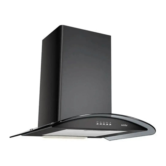
2.2. Drawings of the Appliance 2.2.1 T8630SM / T8631SM / T8632SM / T8731SM /T8930SM / T8931SM / T8932SM Inner Flue Outer Flue Control Panel Filter Lighting 2.2.2. T8633SM / T8634SM / T8933SM / T8934SM / T8635SM /T8935SM / T8636SM /... -
Page 10: T8639Sm / T8939Sm / T8640Sm / T8940Sm / T8649Sm / T8949Sm / T8650Sm / T8950Sm / T8658Sm / T8668Sm / T8645Sm / T8945Sm / T8646Sm / T8946Sm /T7639Sm / T8651Sm / T8653Sm / T8655Sm / T8656Sm / T8673Sm
2.2.3. T8639SM / T8939SM / T8640SM / T8940SM / T8649SM / T8949SM / T8650SM / T8950SM / T8658SM / T8668SM / T8645SM / T8945SM / T8646SM / T8946SM /T7639SM / T8651SM / T8653SM / T8655SM / T8656SM / T8673SM Inner Flue Outer Flue Control panel Filter... -
Page 11: T8954Sm / T8956Sm (Island Type)
Outer Flue Control panel Lighting Filter 3. INSTALLATION OF THE HOOD 3.1. INSTALLATION OF HOOD MODELS T8630SM / T8631SM / T8632SM / T8731SM /T8930SM / T8931SM / T8932SM Electric Cooker Gas Cooker Min: 550 mm. / Max.: 750 mm. Min.: 750 mm. / Max.: 800 mm. -
Page 12: Installation Of The Hanger Plate To The Hood
Installation of the Hanger Plate to the Hood Secure 2 (two) hanger plates provided with the installation accessories to the hood with 1 tightening nut screw as shown in Figure 1. Ensure that the hanger plates are secured in their seats. Installation of the Hanger Plate to the Wall Drive 8 mm dowels to the holes (A, B, C) drilled as per the installation template. -
Page 13: Hanging The Hood To The Wall
Hanging the Hood to the Wall Raise the hood holding its body and connect hanging plates to the dowels on the wall as shown in Figure 3. Figure 3 Figure 4 Bringing the Hood to a Parallel Position to the Ground In case of skewness on the appearance of the hood, use adjustment screws shown in Figure 4 to bring the hood parallel to the ground. - Page 14 Figure 6 Since twists and bends in the aluminium pipe will lead to reduction in the air suction power, avoid using twists and bends as much as possible. Place the inner flue and outer flue on the appliance carefully. Secure the inner flue to the inner flue connection plate with 2 screws.
-
Page 15: Installation Of Hood Models T8633Sm / T8634Sm / T8933Sm / T8934Sm / T8635Sm /T8935Sm / T8636Sm / T8936Sm / T8638Sm / T8938Sm /T8670Sm / T8671Sm / T8652Sm / T8952Sm
3.2. INSTALLATION OF HOOD MODELS T8633SM / T8634SM / T8933SM / T8934SM / T8635SM /T8935SM / T8636SM / T8936SM / T8638SM / T8938SM /T8670SM / T8671SM / T8652SM / T8952SM Electric Cooker Gas Cooker Min: 650 mm. / Max.: 750 mm. Min: 750 mm. -
Page 16: Installation Of The Inner Flue Hanger Plate
Installation Template Figure 1 Picture Installation of the Inner Flue Hanger Plate Drill 2 securing holes on the wall at a suitable height and at required locations using a Ø6mm drill to secure the inner flue hanger plate. Drive 6 mm dowels to these holes and secure the inner flue hanger plate. -
Page 17: Installation Of The Aluminium Pipe
Tighten the bolts shown in Figure 5 securely when the levelling operation is complete. After securing the hood completely, secure the body from the holes (C, D) on the body using two screws to prevent it from moving. Figure 5 Installation of the Aluminium Pipe Mount the flexible aluminium pipe on the plastic flue. -
Page 18: Installation Of Hood Models T8639Sm / T8939Sm / T8640Sm / T8940Sm / T8649Sm / T8949Sm / T8650Sm / T8950Sm / T8658Sm / T8668Sm / T8645Sm / T8945Sm / T8646Sm / T8946Sm /T7639Sm / T8651Sm / T8653Sm / T8655Sm / T8656Sm / T8673Sm
Figure 7 Figure 8 Figure 9 3.3. INSTALLATION OF HOOD MODELS T8639SM / T8939SM / T8640SM / T8940SM / T8649SM / T8949SM / T8650SM / T8950SM / T8658SM / T8668SM / T8645SM / T8945SM / T8646SM / T8946SM /T7639SM / T8651SM / T8653SM / T8655SM / T8656SM / T8673SM Gas Cooker Electric Cooker... -
Page 19: Installation Of The Hanger Plate To The Hood
Installation of the Hanger Plate to the Hood Secure 2 (two) hanger plates provided with the installation accessories to the hood with 1 tightening nut screw as shown in Figure 1. Ensure that the hanger plates are secured in their seats. Installation of the Hanger Plate to the Wall Drive 8 mm dowels to the holes (A, B, C) drilled as per the installation template. -
Page 20: Bringing The Hood To A Parallel Position To The Ground
Bringing the Hood to a Parallel Position to the Ground In case of skewness on the appearance of the hood, use adjustment screws shown in Figure 4 to bring the hood parallel to the ground. Tighten the bolts shown in Figure 5 securely when the levelling operation is complete. -
Page 21: Installation Of Hood Models T8643Sm / T8644Sm / T8743Sm / T8743Sm / T8744Sm / T8641Sm / T8642Sm
Figure 8 Figure 7 Figure 9 3.4. INSTALLATION OF HOOD MODELS T8643SM / T8644SM / T8743SM / T8743SM / T8744SM / T8641SM / T8642SM Electric Cooker Gas Cooker Min.: 650 mm. / Max.: 750 mm. Min.: 750 mm./ Max.: 800 mm. -
Page 22: Installation Of The Hanger Plate To The Hood
Installation of the Hanger Plate to the Hood Secure 2 (two) hanger plates provided with the installation accessories to the hood with 1 tightening nut screw as shown in Figure 1. Ensure that the hanger plates are secured in their seats. Installation of the Hanger Plate to the Wall Drive 8 mm dowels to the holes (A, B, C) drilled as per the installation template. -
Page 23: Bringing The Hood To A Parallel Position To The Ground
Figure 3 Figure 4 Bringing the Hood to a Parallel Position to the Ground In case of skewness on the appearance of the hood, use adjustment screws shown in Figure 4 to bring the hood parallel to the ground. Tighten the bolts shown in Figure 5 securely when the levelling operation is complete. - Page 24 Figure 6 Since twists and bends in the aluminium pipe will lead to reduction in the air suction power, avoid using twists and bends as much as possible. Place the inner flue and outer flue on the appliance carefully. Secure the inner flue to the inner flue connection plate with 2 screws.
-
Page 25: Installation Of Hood Models T8954Sm / T8956Sm (Island Type)
3.5. INSTALLATION OF HOOD MODELS T8954SM / T8956SM (Island Type) Electric Cooker Gas Cooker Min.: 650 mm./ Max.: 750 mm. Min.: 750 mm. / Max.: 800 mm. Preparation of the Hood Upper Assembly Connect 4 hanger rods provided together with the installation accessories to the ceiling plate with 4 screws as shown in Figure 1. -
Page 26: Installation Of The Hood Upper Assembly To The Ceiling
FRONT Installation Template Figure 2 Figure 1 Installation of the Hood Upper Assembly to the Ceiling Drive 6 mm steel dowels to the holes (A, B, C, D) drilled as per the installation template. Secure the hood upper assembly prepared to the ceiling using the nuts on the dowels. -
Page 27: Installation Of The Motor Box
Installation of the Motor Box Select the appropriate height to suspend the hood. Connect the motor box using this height as shown in Figure 4. You may also use the gauge plate to secure the appliance better, if required. Gauge Plate Figure 4 Installation of the Aluminium Pipe... - Page 28 Figure 5 Figure 6 Installation of the Interior Flue If you are installing the appliance directly to a ceiling with no plasterboard, install the inner flue to the holes on the left and right sides of the ceiling connection plate using 2 screws for each side (See Figure 7) If your ceiling is covered with plasterboard, affix the Inox Crown...
-
Page 29: Installation Of The Outer Flue
Installation of the Outer Flue Install the outer flue so that inner flue properly fits in the outer flue. Then screw an empty hole on the motor box and place the outer flue over this screw in order to install the main body on the motor box easily. (See Figure 9) Figure 9 Suspend the main body to the motor box with the hanger hooks shown in Figure 10/1. - Page 30 Figure 10...
-
Page 31: Functions Of The Hood
There are 5 main model groups in the hood product family. If we number each of these groups: Appliance Model Group No: 1 • T8630SM /T8631SM /T8632SM / T8731SM /T8930SM / T8931SM / T8932SM Appliance Model Group No: 2 • T8633SM / T8634SM / T8933SM / T8934SM / T8635SM / T8935SM /... -
Page 32: Touch Control (Applicable Models)
Touch Control (applicable models): Just touch the symbols on the glass. (Touching the symbols for a longer period may activate different functions) Digital Control (applicable models): Just touch the symbols on the glass. The same key is used for motor on/off and time setting functions, and on/off function shall activate if you keep it pressed for 1 second. -
Page 33: Push Pull (Applicable Models)
Symbol Func tion Turns off the motor. (Excluding the lighting system) Motor operates at low speed. Motor operates at medium speed. Motor operates at maximum speed. Turns the lighting system on and off only. Push Pull (applicable models): Lighting is off when the switch is pressed in. Lighting system turned on when the switch is taken out by pressing it. -
Page 34: Round Carbon Filter
Round Carbon Filter Round carbon filters shall be used for filtering the air and returning it to the room in rooms without a flue. You may procure the round carbon filter from your dealer or authorized service. Usage of the Carbon Filter •... -
Page 35: Maintenance And Cleaning Of The Hood
5. MAINTENANCE AND CLEANING OF THE HOOD • The cooker hood must be unplugged or the switch must be turned off before maintenance and cleaning processes. • Metal filter must be washed in hot soaped water or in the dishwasher, if possible, once a month. -
Page 36: Installation / Removal Of The Components
6. INSTALLATION / REMOVAL OF THE COMPONENTS Secure the installation template using the water level on the wall and tape it from its corners. Drill from the indicated corners to install the expansion bolt to the hole. - Page 37 6.1. ASSEMBLY Place the ventilation valves to their positions. Connect the multi-connection flange to the flue.
- Page 38 Secure the flue cap from its screw holes. Strip the flue from its protective plastic film. Place the inner flue to the outer flue after removing the protective film.
- Page 39 Secure the flue connection plate with screws both from left and right sides. Secure the flue connection plate with screws both from left and right sides.
- Page 40 If a flue hose shall be used, place the metal flues before installing them from the bottom and secure the metal flues to the wall using the flue connection plate from the top. If a carbon filter is available, place the filters to the left and right of fan plastic by rotating them.
-
Page 41: Removal
Connect the power cord to the power source. 6.2 REMOVAL 6.2.1. Removal of Oil Filter Open the front panel. Press on the lever on the oil filter and raise the filter. -
Page 42: Removal Of The Lamp
6.2.2. Removal of the Lamp Open the front panel and remove the oil filter. Remove the circuit board cover and replace the circuit board. -
Page 43: Removal And Reinstallation
6.3. REMOVAL AND REINSTALLATION 6.3.1. Removal of the Lamp Remove the display panel as shown figure first disconnect the fan plastic. Then, remove the fan plastic from the upper and rear sides of the flue cap. After removing the fan plastic, remove the connector from its seat by pushing it from its sides. - Page 44 Raise all 5 pins around the fan plastic. Open the fan plastic as shown in the figure. Remove the fan using the wrench.
- Page 45 Remove the motor from its location. Then, remove the cable connections of the motor. When the required maintenance is complete, secure the cables to their locations and screw them again. Remove the display panel to access the lamps. Then, remove them from their seats.
- Page 46 Disconnect the lamp from cable ends. Remove the shock absorber from its location.
- Page 47 Remove the front panel using the driver on the right and socket wrench on the left. Remove the carbon filter on the fan motor. Refer to the image. Install the new carbon filter to the fan motor.
-
Page 48: Circuit Diagrams
7. CIRCUIT DIAGRAMS With Candle Lamp, Push Button Control YELLOW-GREEN PUSH BUTTON CONTROL SWITCH... -
Page 49: With Led Lamp (2 Pieces), Touch Control
With LED Lamp (2 pieces), Touch Control YELLOW-GREY... -
Page 50: With Led Lamp (3 Pieces), Touch Control
With LED Lamp (3 pieces), Touch Control YELLOW-GREEN... -
Page 51: With Led Lamp (4 Pieces), Touch Control
With LED Lamp (4 pieces), Touch Control YELLOW-GREEN... -
Page 52: Exploded View / Spare Part List
8. EXPLODED VIEW / SPARE PART LIST T8630SM /T8631SM /T8632SM / T8731SM /T8930SM / T8931SM / T8932SM... - Page 54 H35-30-280-003 LAMP SOCKET ASSEMBLY 400mm PLUG H35-30-280-004 LAMP PLUG 28 W Y8630-9000-001-63 GLASS SCREW ASSEMBLY Y8932-10BB-0001-63 BODY ASSEMBLY STANDARD 90cm CARETTA WHITE WITH SIMFER INSCRIPTION Y1000-90SF-001-70 PLS. HOOD LAMP PROTECTION WITH DOUBLE LAMP (POLYCARBONATE) H35-30-240-007 SWITCH PUSH BUTTON SET 400mm H65-10-000-001 FILTER 60cm ALM.
-
Page 55: T8633Sm / T8634Sm / T8933Sm / T8934Sm / T8635Sm / T8935Sm / T8636Sm / T8936Sm / T8638Sm / T8938Sm /T8670Sm / T8671Sm / T8652Sm / T8952Sm
T8633SM / T8634SM / T8933SM / T8934SM / T8635SM / T8935SM / T8636SM / T8936SM / T8638SM / T8938SM /T8670SM / T8671SM / T8652SM / T8952SM... - Page 57 SEQUENCE PART CODE PART NAME QTY. Y8633-20IM-001-63 FLUE ASSEMBLY INNER - OUTER SHARP DECORATIVE INOX PLS. HOOD ADAPTOR FLUE Ø120-Ø150 Y1000-90SP-001-70 BLACK (PP) Y1000-90SP-010-70 PLS. HOOD SCROLL FLUE FLAP BLACK (PP) Y1016-9000-003-50 DECORATIVE SCROLL ASSEMBLY Y1000-9000-001-69 HOOD FILTER CARBON SET H35-15-220-008 CABLE PVC 800mm 5SPD MOTOR INTERCONNECTION...
-
Page 58: T8639Sm / T8939Sm / T8640Sm / T8940Sm / T8649Sm / T8949Sm / T8650Sm / T8950Sm / T8658Sm / T8668Sm / T8645Sm / T8945Sm / T8646Sm / T8946Sm / T7639Sm / T8651Sm / T8653Sm / T8655Sm / T8656Sm / T8673Sm
T8639SM / T8939SM / T8640SM / T8940SM / T8649SM / T8949SM / T8650SM / T8950SM / T8658SM / T8668SM / T8645SM / T8945SM / T8646SM / T8946SM / T7639SM / T8651SM / T8653SM / T8655SM / T8656SM / T8673SM... - Page 60 SEQUENCE PART CODE PART NAME QTY. Y8639-0000-900-002 8639 DOUBLE FLUE BLACK SET ANTHRACITE PLS. HOOD ADAPTOR FLUE Ø120- Y1000-00SP-054-001 Ø150 BLACK (PP) Y1000-00SP-054-010 PLS. HOOD SCROLL FLUE FLAP BLACK (PP) Y8639-0000-047-001 DECORATIVE SCROLL ASSEMBLY Y1000-0000-900-001 HOOD FILTER CARBON SET H35-15-220-008 CABLE PVC 800mm 5SPD MOTOR INTERCONNECTION WIRING HOOD...
-
Page 61: T8643Sm / T8644Sm / T8743Sm / T8743Sm / T8744Sm / T8641Sm / T8642Sm
T8643SM / T8644SM / T8743SM / T8743SM / T8744SM / T8641SM / T8642SM... - Page 63 SEQUENCE PART CODE PART NAME QTY. Y8639-0000-047-001 8639 DOUBLE FLUE INOX SET PLS. HOOD ADAPTOR FLUE Ø120- Y1000-00SP-054-001 Ø150 BLACK (PP) Y1000-00SP-054-010 PLS. HOOD SCROLL FLUE FLAP BLACK (PP) Y8639-0000-047-001 DECORATIVE SCROLL ASSEMBLY Y1000-0000-900-001 HOOD FILTER CARBON SET H35-15-220-008 CABLE PVC 800mm 5SPD MOTOR INTERCONNECTION WIRING HOOD H35-30-460-007...
-
Page 64: T8954Sm / T8956Sm (Island Type Hoods)
T8954SM / T8956SM (Island Type Hoods) - Page 66 SEQUENCE PART CODE PART NAME QTY. Y3019-9000-001-68 INSTALLATION ACCESSORIES CARETTA ISLAND H65-10-000-002 FILTER METAL CARETTA ISLAND H35-30-240-008 SWITCH SET TOUCH CONTROL GLASS TOP HOOD H35-15-220-009 CABLE PVC 450mm CONTROL PANEL- HOOD H35-30-100-015 SIGNAL LAMP COLD WHITE (1W MODULE) HOOD H15-35-000-004 GLASS HOOD SMOKE COLOURED 90cm OVAL ISLAND MODEL (8954) Y1000-90SP-015-70...
Need help?
Do you have a question about the T8630SM and is the answer not in the manual?
Questions and answers