Table of Contents
Advertisement
Quick Links
Advertisement
Table of Contents

Related Manuals for MEDENUS R 51


Summary of Contents for MEDENUS R 51
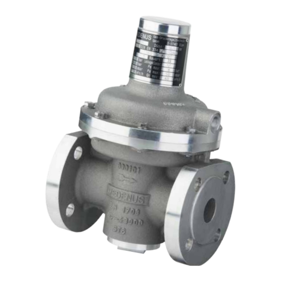
- Page 1 Gas Pressure Regulator R 51 Operating and Maintenance Instructions © 05.2022...
- Page 2 Subject to technical modifications! Reprint prohibited!
- Page 3 Design of the gas pressure regulator R 51 Adjusting screw Diaphragm assembly Diaphragm Internal measurement port Spindle Actuator housing...
-
Page 4: Table Of Contents
For oxygen models, a suitable grease which is approved for the use with oxygen must be used. 9 Troubleshooting 9.1 Gas Pressure Regulator 10 Replacement and Disposal 11 Spare Parts 11.1 Parts for Maintenance Work O-rings Valve Plates / Diaphragms 11.2 Spare Part Sectional View R 51 Notes... - Page 5 12 Accessories / Options 12.1 BV breather valve 12.2 RSD restrictor valve 12.3 HD-2 version 13 Declaration of Conformity...
-
Page 6: General Information
The figures in these instructions are provided for basic understanding and may differ from the actual design. The contents of these instructions are protected by copyright. They may be used as part of operating the device. Any other use and / or reproduction is not permitted without prior authorization by the MEDENUS ©... -
Page 7: Symbols, Notes
1.2 Symbols, Notes The instructions contain safety instructions marked with symbols to indicate possible consequences in case of non- observance: This combination of symbol and signal word indicates a potentially hazardous situation which, if not avoided, may result in minor or moderate injury, damage ATTENTION to the device, the breakdown of the system, and material or environmental damage. -
Page 8: Application, Characteristics
2 Application, Charac- teristics 2.1 Application Gas pressure regulator (GDR), direct-acting (operating without auxiliary power), for systems acc. to DVGW work sheets G 491 (A) and G 600 (A) (TRGI) Particularly suitable for dynamic regulation sections (e.g. natural gas supply systems, low flow regulators, burner circuits, gas motor operation) Can be used for the gases defined in DVGW work sheets G 260 / G 262 and neutral non-aggressive gases. -
Page 9: Safety Instructions
Using the device under different operating conditions must be agreed upon in consultation with MEDENUS Gas-Druckregeltechnik GmbH. The mechanical components of the device do not have any potential ignition sources of their own nor any hot surfaces and are thus not covered by the scope of 2014/34/EU (ATEX). -
Page 10: Safety In Operation
(alarm and hazard prevention plan). In particular, the following applies: • The operator is obliged to perform work on MEDENUS devices during the warranty period only © after consultation with the manufacturer. Otherwise the claims under warranty will become void. -
Page 11: Transport, Storage And Packaging
6 Transport, Storage and Packaging 6.1 Transport The device is delivered with flange protection caps. They must be removed prior to installation. Note Make sure that the device is transported horizontally using suitable lifting gear. The device must be handled carefully and secured against impacts and knocks. In case of transport damage, we will require the following information from the nameplate affixed to the device: •... -
Page 12: Mounting And Commissioning
For the assembly of the flange connections, the maximum values specified by the flange and gasket manufacturers must be observed. Note Max. flange tightening torque: M12 (60 Nm), M16 (120 Nm), M20 (190 Nm) In installation positions other than horizontal, MEDENUS Gas-Druckregeltechnik GmbH must be consulted. • All breather lines (items 5.04 / 5.07) must be vented to the outside atmosphere. - Page 13 Range for 5.04 5.09 measuring points* 5.12 (approx. 3x DN P 5.10 5.13 5.07 5.03 5.11 5.01 5.02 5.06 5.08 5.05 5.28 Ø Connection Anschluss Regler Anschluss Regler Nennweite / Öffnungsdurchmesser / Abmessung / nominal /connection dimension (mm) connection Regulator size Regulator opening diameter (mm)
-
Page 14: Leakage Test (Test For External Leakage)
7.3 Leakage Test (Test for External Leakage) The devices are subjected to a strength and leakage test ex works at MEDENUS Gas-Druckregeltechnik GmbH. The leakage test in the fully assembled system must be performed prior to commissioning and following maintenance work. -
Page 15: Initial Commissioning / Recommissioning
Initial commissioning of the system components shall be carried out by the operator. For commissioning, please refer to the documents listed under item 1 “General Information” and the system operator's work instruction. The devices delivered by MEDENUS Gas-Druckregeltechnik GmbH are factory-set to the operating data specified by the customer. This data is listed on the Acceptance Test Certificate (ATC)* and the type plate. - Page 16 Changing the control range Switching to the control range of a different setpoint spring can be done for the GPR while the device is pressurized. Gas pressure regulator • Take off the sealing cap (item 7.21) and unscrew the setting screw (item 7.22), •...
-
Page 17: Decommissioning
7.6 Decommissioning For decommissioning, please refer to the documents listed under item 1 “General Information” and the system operator's work instruction. Procedure • Slowly close the outlet shut-off valve (item 7.13) • Close the ball valve upstream of the valves and fittings (item 7.01). • Depressurize the system (item 7.11). • Close the venting ball valve (item 7.11). 8 Maintenance 8.1 Maintenance Plan The maintenance regulations of the system manufacturer must be observed. -
Page 18: Maintenance Procedure
8.2 Maintenance Procedure The maintenance procedure is described in detail step-by-step in our video tutorial and our pictorial descriptions. Instructions for our products can be found in the download area of our website. Should you have any problems, please feel free to contact us directly. ATTENTION If components have been removed, make sure they are mounted correctly, reinstall all fastening elements and observe the screw tightening torques. -
Page 19: Troubleshooting
9 Troubleshooting 9.1 Gas Pressure Regulator Description of the error Possible cause Elimination Check valve plate (seal) and valve seat for damage Actuator dirty or damaged and dirt, replace valve plate, if necessary Static sealing elements defective Replace O-rings Clamping of the compensating Closing pressure too diaphragm has come off Check compensating diaphragm for fastening,... -
Page 20: Replacement And Disposal
The remaining components should be disposed of after sorting according to material. For technical information, please contact our customer service: MEDENUS Gas-Druckregeltechnik GmbH Phone +49 (0) 2761 / 82788-0 E-mail service@medenus.de © Im Langen Feld 3 Fax +49 (0) 2761 / 82788-9 Internet www.medenus.de... -
Page 21: Spare Part Sectional View R
11.2 Spare Part Sectional View R 51 R51 shown with high-pressure spindle HD2 © 05.2022... -
Page 22: Notes
Notes ................ - Page 23 12 Accessories / Options 12.1 BV breather valve 12.1.1 Use • On SAV control devices • On regulators (pilots) • With low-dynamic regulation sections (one full stroke) • On the SRV (SL10) 12.1.2 Application / Function The breather valve is used as replacement for the costly and time-consuming laying of breather lines and for securing the installation room against inadmissible escape of gas from diaphragm comparator compartments of gas pressure regulators and safety shut-off valves.
- Page 24 12.2 RSD restrictor valve 12.2.1 Use • For installation in the measurement line of the gas pressure regulator 12.2.2 Application / Function • For finer adjustment of the control behavior of the regulator • For vibration-free outlet pressure regulation. The RSD is a throttle valve that affects the volumetric flow in the measurement line from outside by means of a continuously adjustable narrowing of the cross-section.
- Page 25 12.3 HD-2 version 12.3.1 Use • Gas pressure regulators R51 • On the SRV (SL10) 12.3.2 Application / Function The HD-2 high-pressure spindle is used for simplified adjustment of the control spring in the safety relief valve SRV. For the adjustment of particularly strong control springs, the use of a high-pressure spindle is mandatory.
- Page 26 © 05.2022...
- Page 27 In the download area of our homepage, this document is available in different languages. You can use the following QR codes and links to go directly to this document in your language. German: http://medenus.de/files/upload/ downloads/R51/BWA_R51_de.pdf © 05.2022...
- Page 28 MEDENUS Gas-Druckregeltechnik GmbH Phone +49 (0)2761 82788-0 +49 (0)2761 82788-9 Im Langen Feld 3 / D-57462 Olpe info@medenus.de www.medenus.de...
Need help?
Do you have a question about the R 51 and is the answer not in the manual?
Questions and answers