
Related Manuals for MEDENUS R 100


Summary of Contents for MEDENUS R 100
- Page 1 Gas Pressure Regulator R 100 / R 100U Accessories / Options Operating and Maintenance Instructions © 05.2022...
- Page 2 Reprint prohibited! Subject to technical modifications!
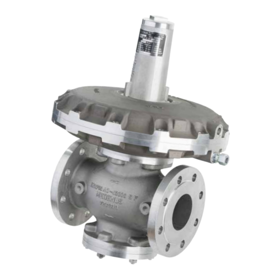
- Page 3 Design of the gas pressure regulator R 100 / R 100U Diaphragm assembly Main diaphragm Actuator housing Double seat valve shown R 100 R 100 U is shown...
-
Page 4: Table Of Contents
Table of Contents 1 General Information 1.1 Warranty and Liability 1.2 Symbols, Notes 1.3 Terms, Abbreviations 2 Application, Characteristics 2.1 Application 2.2 Characteristics 2.3 Types of Models (Options) 3 Avoidance of Foreseeable Misuse 4 Safety Instructions 4.1 Hazards of Handling the Device 4.2 Personnel Requirements 4.3 Country-Specific Requirements 4.4 Handover of the Operating and Maintenance Instructions... - Page 5 12 Accessories / Options 12.1 High-pressure spindle 12.2 RSD restrictor valve 12.3 Safety diaphragm 13 Tools 13.1 Brace and bit with 4-jaw chuck29 13.2 SSV tightening tool Declaration of Conformity...
-
Page 6: General Information
The figures in these instructions are provided for basic understanding and may differ from the actual design. The contents of these instructions are protected by copyright. They may be used as part of operating the device. Any other use and/or reproduction is not permitted without prior authorization by MEDENUS Gas- Druckregeltechnik GmbH. -
Page 7: Symbols, Notes
1.2 Symbols, Notes The instructions contain safety instructions marked with symbols to indicate possible consequences in case of non- observance: This combination of symbol and signal word indicates a potentially hazardous situation which, if not avoided, may result in minor or moderate injury, damage ATTENTION to the device, the breakdown of the system, and material or environmental damage. -
Page 8: Application, Characteristics
2 Application, Character- istics 2.1 Application Gas pressure regulator (GDR), direct-acting (operating without auxiliary power), for systems acc. to DVGW work sheets G 491 (A) and G 600 (A) (TRGI) Particularly suitable for dynamic regulation sections (e.g. gas fireplaces, natural gas supply systems, burner circuits, gas motor operation) Can be used as an equipment component on gas consumption facilities as defined in Regulation (EU) 2016/426. -
Page 9: Safety Instructions
Using the device under different operating conditions must be agreed upon in consultation with MEDENUS Gas-Druckregeltechnik GmbH. The mechanical components of the device do not have any potential ignition sources of their own nor any hot surfaces and are thus not covered by the scope of 2014/34/EU (ATEX). -
Page 10: Safety In Operation
(alarm and hazard prevention plan). In particular, the following applies: • The operator is obliged to perform work on MEDENUS devices during the warranty period only © after consultation with the manufacturer. Otherwise the claims under warranty will become void. -
Page 11: Transport, Storage And Packaging
6 Transport, Storage and Packaging 6.1 Transport The device is delivered with flange protection caps. They must be removed prior to installation. Note Make sure that the device is transported horizontally using suitable lifting gear. The device must be handled carefully and secured against impacts and knocks. In case of transport damage, we will require the following information from the nameplate affixed to the device: •... -
Page 12: Mounting And Commissioning
7 Mounting and Commissioning 7.1 Safety Instructions and Preparation Prior to starting work on pressurized components: DANGER • Close all connections to the gas line. • Depressurize all pressurized components. Also discharge residual energies. • Defective components charged with pressure in operation must be replaced immediately by an appropriate expert. - Page 13 Gas pressure control section R100 5.13 5.11 5.09 R100 5.12 5.10 Range for 5.04 5.03 measuring points* 5.01 Outlet (approx. 3x DN P 5.02 5.05 5.07 Inlet 5.27 5.08 5.26 5.06 5.28 Gas pressure control section R100-U Return line / Inlet pressure line MQMe quantometer with electronic...
-
Page 14: Leakage Test (Test For External Leakage)
7.3 Leakage Test (Test for External Leakage) The devices are subjected to a strength and leakage test ex works at MEDENUS Gas-Druckregeltechnik GmbH. The leakage test in the fully assembled system must be performed prior to commissioning and following maintenance work. -
Page 15: Initial Commissioning / Recommissioning
Initial commissioning of the system components shall be carried out by the operator. For commissioning, please refer to the documents listed under item 1 “General Information” and the system operator's work instruction. The devices delivered by MEDENUS Gas-Druckregeltechnik GmbH are factory-set to the operating data specified by the customer. This data is listed on the Acceptance Test Certificate “ATC” (available as an option) and the type plate. Prior to commissioning of the system, a functional test must be performed on the gas pressure regulator (GPR), if applicable, and the safety shut-off and safety relief valves. -
Page 16: Control Spring Setpoint Table
*) with high-pressure spindle Diaphragm assembly setpoint spring R 100-U For more detailed information on the setpoint spring ranges for the gas pressure regulator R 100-U, please contact the company MEDENUS Gas Pressure Regulation. The contact data are given under item 10. -
Page 17: Decommissioning
7.6 Decommissioning For decommissioning, please refer to the documents listed under item 1 “General Information” and the system operator's work instruction. Procedure • Slowly close the outlet shut-off valve (item 5.13) or 5.22 • Slowly lower the outlet pressure via the setpoint setting screw until the reserve rail takes over the gas supply or •... -
Page 18: Maintenance
8 Maintenance 8.1 Maintenance Plan The maintenance regulations of the system manufacturer must be observed. The following sections describe the maintenance work required for optimal and trouble-free operation of the device. If increased wear is detected during regular inspections, the required maintenance intervals must be shortened in accordance with the actual wear. -
Page 19: Table Of Screw Tightening Torques M
8.3 Table of Screw Tightening Torques M R100 / 050 Item R100 / 150 Exception R100 / 080 R100 / 200 R100 / 100 M10 / 36 Nm M10 / 36 Nm RE 160 M8 / 18 Nm M8 / 18 Nm M10 / 36 Nm M12 / 62 Nm M10 / 36 Nm M12 / 62 Nm 8.4 Lubricants Table Components (apply a thin layer) Lubricants Article no. -
Page 20: Troubleshooting
9 Troubleshooting 9.1 Gas Pressure Regulator Description of the error Possible cause Elimination Check valve plate (seal) and valve seat for damage Actuator dirty or damaged and dirt, replace valve plate, if necessary Closing pressure too Static sealing elements defective Replace O-rings high Valve plate has become disconnected... -
Page 21: Replacement And Disposal
If no return or disposal agreement has been signed, disassembled components should be recycled: • Metals should be scrapped • The remaining components should be disposed of after sorting according to material. For technical information, please contact our customer service: MEDENUS Gas-Druckregeltechnik GmbH Phone +49 (0) 2761 / 82788-0 E-mail service@medenus.de Im Langen Feld 3 Fax +49 (0) 2761 / 82788-9 Internet www.medenus.de... -
Page 22: Spare Parts
11.2 Optional Spare Parts Drawing R100 shown with High-pressure spindle HDS R100 shown with safety diaphragm R 100-U is shown R100 shown with tripod 27 (spring washer) 1x O-ring at RE 160 / 205 / 275 / 385 / 485 (4x O-ring at RE 320 / 390) ©... -
Page 23: Parts For Maintenance Work
Valve plate R100 / R100-U (standard e.g. VT-102 / Viton e.g. VT-102-V) Item no. Quantity pcs. Valve (6.1) Valve (6.2) R 100 / 050 R100 / 080 R 100 / 100 R 100 / 150 R 100 / 200 VT-003 27.5... -
Page 24: O-Rings And Sealing Rings R100 / R100-U
O-rings and sealing rings R100 / R100-U Item Name Quantity Exception R100 (-U) / 050 R100 (-U) / 150 R100 (-U) / 200 pcs. R100 (-U) / 080 R100 (-U) / 100 O-ring O-036 O-045 O-046 O-ring O-009 O-009 O-009 O-021 O-030 O-030... -
Page 25: Notes
Example: DN - RE - Main D - Nozzle (valve Designation: Type Nominal Diaphragm diaphragm Option diameter) width assembly Gas pressure R100 390* 27.5-27.5 SM... regulator: Gas pressure regulator: R100 / 050 / 390* / 27.5 - 27.5 / MB* Spare parts according to tables in 11.3 MS-152 Main diaphragm and O-ring:... -
Page 26: Accessories / Options
12.2.1 Use • Gas pressure regulators RS 250 / RS 251 • Gas pressure regulators RS 254 / RS 255 • Gas pressure regulators R 100 / R 100-U • Gas pressure regulators R101 12.2.2 Application / Function The HDS high-pressure spindle is used for simplified adjustment of the control spring in the gas pressure regulator. -
Page 27: Rsd Restrictor Valve
12.2 RSD Restrictor Valve 12.2.1 Use • For installation in the measurement line of the gas pressure regulator 12.2.2 Application / Function • For finer adjustment of the control behavior of the regulator • For vibration-free outlet pressure regulation. The RSD is a throttle valve that affects the volumetric flow in the measurement line from outside by means of a continuously adjustable narrowing of the cross-section. -
Page 28: Safety Diaphragm
12.03.1 Use • Gas pressure regulators RS 250 / RS 251 • Gas pressure regulators RS 254 / RS 255 • Gas pressure regulators R 100 / R 100-U • Gas pressure regulators R101 12.03.2 Application / Function In the model with safety diaphragm, the safety diaphragm is located above the main diaphragm. When the main diaphragm ruptures, the safety diaphragm makes contact with the top cover of the diaphragm assembly and prevents any inadmissible escape of gas into the surrounding atmosphere. -
Page 29: Tools
13.1 Brace and bit with 4-jaw chuck The 3.5 - 16 mm brace and bit with 4-jaw chuck and the accessories available for it are used for precise adjustment of the setpoint spring in your MEDENUS gas pressure regulator. For further information for use and on the spring data of the setpoint springs, please refer to pages 12 - 13 "Initial commissioning / Recommissioning"... -
Page 30: Declaration Of Conformity
© 05.2022... - Page 31 In the download area of our homepage, this document is available in different languages. You can use the following QR codes and links to go directly to this document in your language. German: http://medenus.de/files/upload/ downloads/R100/BWA_R100_de.pdf...
- Page 32 MEDENUS Gas-Druckregeltechnik GmbH Phone +49 (0)2761 82788-0 Fax +49 (0)2761 82788-9 Im Langen Feld 3 / D-57462 Olpe info@medenus.de www.medenus.de...
Need help?
Do you have a question about the R 100 and is the answer not in the manual?
Questions and answers