Advertisement
Description
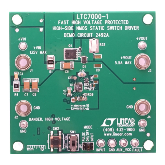
Demonstration circuit 2492A is a 135V protected, high
side switch featuring the
designed to switch a 5.5A output load from input voltages
from 8V to 135V. The wide input range and low shutdown
current (1µA typical) make it suitable for automotive,
industrial, medical instrument and telecom applications.
This board offers a low 50ns (typical) propagation delay,
fast switching times (<10ns) and 100% duty cycle opera-
tion.
The LTC7000-1 is a fast high voltage protected high side
N-channel MOSFET driver with high voltage pin spacing
(0.657mm). An internal charge pump fully enhances an
external N-channel MOSFET switch, allowing it to remain
on indefinitely. A powerful gate driver can drive large gate
capacitance MOSFETs with very short transition times,
ideal for both high frequency switching and static switch
applications. The LTC7000-1 operates over a 3.5V to 135V
input supply range. When an external current sense resis-
tor and internal comparator sense that the switch current
has exceeded a preset level, a fault flag is asserted and
the switch is turned off after a period of time set by an
external timing capacitor. After a cooldown period, the
LTC7000-1 can be configured to automatically retry or
remain off until the input is re-cycled.
performance summary
SYMBOL
PARAMETER
V
Input Voltage
IN
I
Output Current
OUT
Insertion Drop
V
Start-Up Voltage
IN
V
V
Undervoltage Lockout
CCUV
CC
Overcurrent to V
Input to Output Propagation Delay
Output Rise Time
Arrow.com.
Downloaded from
High Side NMOS Static Switch Driver
LTC
7000-1. The demo board is
®
CONDITIONS
V
– V
, 5.5A Load, Input to Output Terminals
IN
OUT
100kΩ Load, V
V
Rising
CC
V
Falling
CC
Hysteresis
Low
Turn-On into a 10A Resistive Load
OUT
V
= 135V, 50Ω Load, INP = 2.2V to V
IN
V
= 135V, 50Ω Load, 10% to 90%
IN
DEMO MANUAL DC2492A
Fast High Voltage Protected
The demo board includes input capacitors and an output
diode to accommodate input and output supply induc-
tance when switching loads. The switch can be controlled
directly with external signal or using the on-board on/
off switch. A single-shot pulse generator is included for
evaluating switching times while limiting output power.
Optional auxiliary V
associated with high frequency switching. Positions for RC
delay network to control inrush current are also included.
The LTC7000-1 data sheet gives a complete description of
the part, operation and application information. The data
sheet must be read in conjunction with this demo manual
for demo circuit 2492A. Proper board layout is essential
for maximum thermal and electrical performance. See the
data sheet sections for details. The LTC7000-1 is available
in 16-lead MSOP package and three operating junction
temperature grades, extended and industrial from –40°C
to 125°C, high temp automotive version from –40°C to
150°C and a military grade from –55°C to 150°C.
Design files for this circuit board are available at
http://www.linear.com/demo/DC2492A
L, LT, LTC, LTM, Linear Technology and the Linear logo are registered trademarks of Analog
Devices, Inc. All other trademarks are the property of their respective owners.
Specifications are at T
= 25°C
A
= 4V
INP
= 13.5V
OUT
LTC7000-1
input accommodates gate power
CC
MIN
TYP
MAX
8.0
135
5.5
150
7.0
8.0
6.5
7.0
7.5
5.8
6.4
6.9
0.6
19
50
6.5
UNITS
V
A
mV
V
V
V
V
µs
ns
ns
dc2492af
1
Advertisement
Table of Contents

Subscribe to Our Youtube Channel
Related Manuals for Linear Technology LTC7000-1


Summary of Contents for Linear Technology LTC7000-1
- Page 1 After a cooldown period, the L, LT, LTC, LTM, Linear Technology and the Linear logo are registered trademarks of Analog LTC7000-1 can be configured to automatically retry or Devices, Inc. All other trademarks are the property of their respective owners.
- Page 2 9. Placing SW1 to OFF position, moving JP1 to INPUT voltage slowly to 8V minimum. The input range is up position connects INPUT terminal to LTC7000-1 INP to 135V but hot-plugging with long leads may result pin. An INPUT pin voltage of 2.2V or more will turn-on in input voltages in excess of 135V.
- Page 3 DEMO MANUAL DC2492A Quick start proceDure – Figure 2. Measuring Output Voltage During Switching across C9. Note that C9 May Not Be Installed typical performance charateristics 50 RESISTIVE LOAD 50V/DIV 5V/DIV DC2492 F03 Figure 3. Rise Time into 50Ω Load (V = 135V, V 5V/DIV, V 50V/DIV, 10ns/DIV)
- Page 4 DEMO MANUAL DC2492A parts list ITEM REFERENCE PART DESCRIPTION MANUFACTURER/PART NUMBER Required Circuit Components C3, C4, C5, C7, C8 CAP ., 1µF, X7T, 250V, 1812 TDK, C4532X7T2E105K250KA C11, C14 CAP ., 1000pF, X7R, 25V, 10%, 0603 MURATA, GRM188R71E102KA01D CAP ., 0.1µF, X7R, 25V, 10%, 0805 AVX, 08053C104KAT2A CAP ., 0.1µF, X7R, 200V, 10%, 1206 AVX, 12062C104KAT2A...
- Page 5 DEMO MANUAL DC2492A parts list ITEM REFERENCE PART DESCRIPTION MANUFACTURER/PART NUMBER R27, R31 RES., 240k, 1/10W, 1%, 0805 VISHAY, CRCW0805240KFKEA RES., 976k, 1/10W, 1%, 0603 VISHAY, CRCW0603976KFKEA RES., 232k, 1/10W, 1%, 0603 VISHAY, CRCW0603232KFKEA RES., 182k, 1/10W, 1%, 0603 VISHAY, CRCW0603182KFKEA RES., SENSE, 0Ω, 1/2W, 1%, 1225 TEPRO, RN5326 SWITCH, SUB MINIATURE SLIDE...
- Page 6 DEMO MANUAL DC2492A schematic Diagram dc2492af Arrow.com. Arrow.com. Arrow.com. Arrow.com. Arrow.com. Arrow.com. Downloaded from Downloaded from Downloaded from Downloaded from Downloaded from Downloaded from...
- Page 7 Information furnished by Linear Technology Corporation is believed to be accurate and reliable. However, no responsibility is assumed for its use. Linear Technology Corporation makes no representa- tion that the interconnection of its circuits as described herein will not infringe on existing patent rights.
- Page 8 Linear Technology Corporation (LTC) provides the enclosed product(s) under the following AS IS conditions: This demonstration board (DEMO BOARD) kit being sold or provided by Linear Technology is intended for use for ENGINEERING DEVELOPMENT OR EVALUATION PURPOSES ONLY and is not provided by LTC for commercial use. As such, the DEMO BOARD herein may not be complete in terms of required design-, marketing-, and/or manufacturing-related protective considerations, including but not limited to product safety measures typically found in finished commercial goods.
Need help?
Do you have a question about the LTC7000-1 and is the answer not in the manual?
Questions and answers