Advertisement
DESCRIPTION
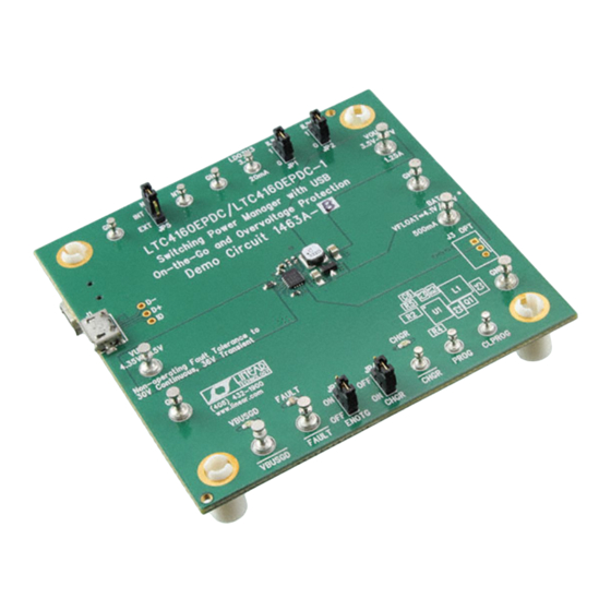
Demonstration Circuit DC1463A is a Switching Power Manager with USB On-the-Go and Overvoltage Protection
®
featuring the LTC
4160.
PERFORMANCE SUMMARY
SYMBOL
PARAMETER
VBUS
Bus Input Voltage Range
V(LDO3V3) 3.3V LDO Output
V(BAT)
Battery Float Voltage
I(BAT)
Battery Charge Current
VOUT
Output Voltage
V
VBUS voltage in OTG mode I(VBUS) ≤ -500mA
OTG
QUICK START PROCEDURE
Refer to Figure 1 for the proper measurement
equipment setup and jumper settings and follow the
procedure below.
When measuring the input or output voltage ripple, care
NOTE.
must be taken to avoid a long ground lead on the oscilloscope
probe. Measure the input or output voltage ripple by touching the
probe tip directly across the VBUS or VOUT(x) and GND terminals.
See Figure 2 for proper scope probe technique.
1. Set all jumpers as shown in Figure 1 and LD1 =
0A, PS1 = 5V, LD2 = 0A, LD3 = 0A, PS2 = 3.6V.
Observe VOUT (VM4), LDO3V3 (VM3), and
V(NTC) (VM2). The LTC4160 is operating as
USB power manager. The current from PS1 will
try to be the charging current * (3.6V/5V), or ap-
LTC4160EPDC / LTC4160EPDC-1
Switching Power Manager with USB
On-the-Go and Overvoltage Protection
Specifications are at T
CONDITIONS
VOUT > 3.5V
LTC4160 Constant Voltage Mode
LTC4160-1 Constant Voltage Mode
Constant Current Mode, R
= 2.00k
PROG
ILIM[1..0] = 01b, I(VOUT) ≤ 1.25A, V(BAT) > 3.6V
I(VOUT) ≤ 1.25A, V(BAT) < 3.6V
2. Increase LD3 to 80mA, and LD2 to 25mA. Ob-
3. Increase LD3 to 250mA. Observe VOUT(VM4),
DEMO CIRCUIT 1463A
QUICK START GUIDE
= 25°C
A
MIN
TYP
4.35
3.1
4.15
4.05
485
V(BAT)
3.6V
4.5
5
proximately 400mA, but will be limited by the in-
put current limiter to ~ 100mA.
serve VOUT(VM4), I(VUSB) (AM1) and LDO3V3
(VM3). Set LD2 to 0A. The loads on VOUT and
LDO3V3 are now reducing the charge current
further.
I(VUSB) (AM1). The load on VOUT will engage
the input current limit, and VOUT will drop until
the ideal diode engages to provide the difference
current.
MAX
UNITS
6
V
3.4
V
4.23
V
4.13
515
mA
VBAT + 0.45V
V
V
5.5
V
1
Advertisement
Table of Contents

Related Manuals for Linear Technology LTC4160EPDC


Summary of Contents for Linear Technology LTC4160EPDC
- Page 1 DEMO CIRCUIT 1463A QUICK START GUIDE LTC4160EPDC / LTC4160EPDC-1 Switching Power Manager with USB On-the-Go and Overvoltage Protection DESCRIPTION Demonstration Circuit DC1463A is a Switching Power Manager with USB On-the-Go and Overvoltage Protection ® featuring the LTC 4160. PERFORMANCE SUMMARY Specifications are at T = 25°C...
- Page 2 LTC4160EPDC/LTC4160EPDC-1 4. Change JP1 & JP2 to ‘1’. Observe VOUT(VM4) and I(VUSB) (AM1). The input current limit is now 500mA, and the load on VOUT is 250mA, so the battery charge current will be approximately 250mA. 5. Increase LD3 to 750mA. Observe VOUT(VM4) and I(VUSB)(AM1).
- Page 3 LTC4160EPDC/LTC4160EPDC-1 Figure 1. Proper Measurement Equipment Setup for DC1463A Figure 2. Measuring Input or Output Ripple...
- Page 4 LTC4160EPDC/LTC4160EPDC-1 Figure 3. Circuit Schematic...
- Page 5 LTC4160EPDC/LTC4160EPDC-1 Figure 4. Bill of Materials...
Need help?
Do you have a question about the LTC4160EPDC and is the answer not in the manual?
Questions and answers