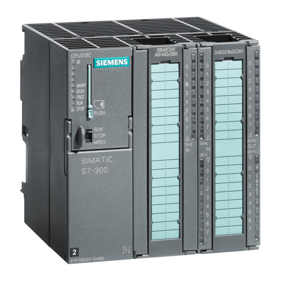
Siemens SIMATIC S7-300 Installation And Hardware Manual
Hide thumbs
Also See for SIMATIC S7-300:
- User manual ,
- Manual (676 pages) ,
- Reference manual (574 pages)
Advertisement
Quick Links
SIMATIC
S7-300 Programmable Controller
Installation and Hardware
Manual
This Manual is Part of the Documentation Package
with the Order Number:
6ES7 398-8AA02-8BA0
EWA 4NEB 710 6078-02a
Edition 2
Preface, Contents
Product Overview
Mechanical Configuration
Addressing the S7-300 Modules
Electrical Configuration
Installing an S7-300
Wiring an S7-300
Configuring an MPI or
PROFIBUS Subnet
Preparing an S7-300 for
Operation and Start-up of
PROFIBUS-DP
Changing the Backup Battery/
Rechargeable Battery, Module
and Fuses
CPUs
CPU 315-2 DP as DP Master/
DP Slave
Cycle Time and Response Time
of the S7-300
Appendices
Glossary, Index
1
2
3
4
5
6
7
8
9
10
11
12
Advertisement

Summary of Contents for Siemens SIMATIC S7-300
- Page 1 Preface, Contents Product Overview Mechanical Configuration Addressing the S7-300 Modules SIMATIC Electrical Configuration Installing an S7-300 S7-300 Programmable Controller Installation and Hardware Wiring an S7-300 Configuring an MPI or PROFIBUS Subnet Manual Preparing an S7-300 for Operation and Start-up of PROFIBUS-DP Changing the Backup Battery/ Rechargeable Battery, Module...
- Page 2 This device and its components may only be used for the applications described in the catalog or the technical description, and only in connection with devices or components from other manufacturers which have been approved or recommended by Siemens. This product can only function correctly and safely if it is transported, stored, set up, and installed correctly, and operated and maintained as recommended.
- Page 3 Preface Purpose of this The information contained in this manual will help you with the following: Manual Install and wire an S7-300 programmable controller, and Look up operator entries, functional descriptions and the technical speci- fications relevant to the S7-300’s CPUs. You will find the function descriptions and technical specifications for the signal modules, power supply modules and interface modules in the Mod- ule Specifications Reference Manual.
- Page 4 Preface Scope of this This manual applies for the following CPUs: Manual Order No. From Version CPU 312 IFM 6ES7 312-5AC01-0AB0 CPU 313 6ES7 313-1AD02-0AB0 CPU 314 6ES7 314-1AE03-0AB0 CPU 314 IFM 6ES7 314-5AE02-0AB0 CPU 315 6ES7 315-1AF02-0AB0 CPU 315-2 DP 6ES7 315-2AF02-0AB0 CPU 316 6ES7 316-1AG00-0AB0...
- Page 5 Reduction in materials used thanks to more compact design and fewer components through integration in ASICs The SIMATIC S7-300 can be recycled thanks to the low level of pollutants in its equipment. Please contact the following address for environmentally-friendly recycling...
- Page 6 Preface Scope of the Docu- Depending on the CPU, you require the following documentation for instal- mentation Package ling your S7-300: The following documentation is required for installing the S7-300 and for preparing it for operation: Documentation package Order No. 6ES7 398-8AA02-0BA0 Hardware and Reference...
- Page 7 Please contact your local Siemens representative if you have any queries tance about the products described in this manual. A list of Siemens representatives worldwide is contained in the appendix to this manual. If you have any questions or suggestions concerning this manual, please fill in the form at the end of this manual and return it to the specified address.
- Page 8 Preface S7-300, Installation and Hardware viii EWA 4NEB 710 6078-02a...
- Page 9 Contents Preface Product Overview Mechanical Configuration Horizontal and Vertical Arrangement of an S7-300 ....Mounting Dimensions of the S7-300 ....... . The Module Arrangement for an S7-300 Configuration on One Rack .
- Page 10 Contents Installing an S7-300 Installing the Rail ..........Module Accessories .
- Page 11 Contents CPUs 10.1 Performance Characteristics ........10-2 10.2 Mode Selector, LEDs and Test Functions...
- Page 12 ........General Protective Measures against Electrostatic Discharge Damage Spare Parts and Accessories for the CPUs of the S7-300 SIMATIC S7 Reference Literature Safety of Electronic Control Equipment Siemens Worldwide List of Abbreviations Glossary Index S7-300, Installation and Hardware...
- Page 13 Contents Figures Components of an S7-300 ........Horizontal and Vertical Arrangements of an S7-300 .
- Page 14 Contents Cable Lengths in an MPI Subnet ........7-17 Bus Connectors 6ES7 ...
- Page 15 Contents Header Information of a Sublist of the System Status List ... . . Structure of the “SZL-ID” of the Sublist ......Dimension Drawing of the CPU 312 IFM .
- Page 16 Contents Possible Reasons for MRES Request by CPU ..... . . 8-11 Internal CPU Events on Memory Reset ......8-13 10-1 Performance Characteristics of the CPUs...
- Page 17 Contents 12-6 Cycle Extension through Nesting of Interrupts ..... . . 12-11 12-7 Process Interrupt Response Times of the CPUs .
- Page 18 Contents S7-300, Installation and Hardware xviii EWA 4NEB 710 6078-02a...
- Page 19 Product Overview Modular Design The S7-300 has a modular design. You can set up your own individual system by combining components from a comprehensive range of S7-300 modules. The range of modules includes the following components: CPUs for various performance ranges Signal modules for digital and analog input/output(see Module Specifica- tions Reference Manual) Function modules for technological functions (see the relevant function...
- Page 20 Product Overview Configuring an An S7-300 programmable controller is made up of the following compo- S7-300 nents: Power supply (PS) Signal modules (SM) Function modules (FM) Communication processor (CP). Several S7-300s can communicate with each other over PROFIBUS bus cables. You require a programming device to program the S7-300.


Need help?
Do you have a question about the SIMATIC S7-300 and is the answer not in the manual?
Questions and answers