
Related Manuals for Peregrine Semiconductor Corporation UltraCMOS SP6T


Summary of Contents for Peregrine Semiconductor Corporation UltraCMOS SP6T
- Page 1 Multi-throw Count RF Switch Evaluation Kit (EVK) User’s Manual SP6T: PE42562, PE42462, PE426462 SP8T: PE42582, PE42482, PE426482 SP12T: PE42512, PE42412, PE426412 DOC-82458-1 – (02/2017) EVK User’s Manual www.psemi.com...
- Page 2 Multi-throw Count RF Switch EVK User’s Manual Copyright and Trademarks ©2017, Peregrine Semiconductor Corporation. All rights reserved. The Peregrine name, logo, UTSi and UltraCMOS are registered trademarks and HaRP, MultiSwitch and DuNE are trademarks of Peregrine Semicon- ductor Corp. Disclaimers The information in this document is believed to be reliable.
-
Page 3: Table Of Contents
Multi-throw Count RF Switch EVK User’s Manual Table of Contents Introduction - - - - - - - - - - - - - - - - - - - - - - - - - - - - - - - - - - - - - - - - - - - - - - - - - - - - - - 1 Introduction - - - - - - - - - - - - - - - - - - - - - - - - - - - - - - - - - - - - - - - - - - - - - - - - - - - - - - - - - - - - - - - - - - - - - - 1 Application Support . - Page 4 Multi-throw Count RF Switch EVK User’s Manual SP8T EVB Functional Overview ................. . 18 SP8T Hardware Operation .
-
Page 5: Introduction
Multi-throw Count RF Switch EVK User’s Manual Introduction Introduction The SP6T (PE42562, PE42462, PE426462), SP8T (PE42582, PE42482, PE426482) and SP12T (PE42512, PE42412, PE426412) are HaRP™ technology-enhanced absorptive high throw count RF switches manufac- ® tured on Peregrine’s UltraCMOS process, a patented variation of silicon-on-insulator (SOI) technology. These products deliver high port-to-port isolation, low insertion loss and fast switching time, making them ideal for filter bank switching and RF signal routing in test and measurement (T&M) and wireless applications up to 8 GHz. -
Page 6: Evaluation Kit Contents And Requirements
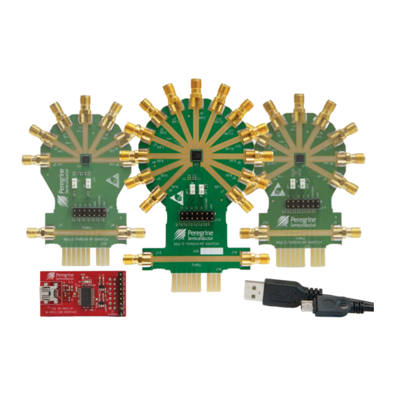
Multi-throw Count RF Switch EVK User’s Manual Evaluation Kit Contents and Requirements Kit Contents The Multi-throw Count RF Switch EVK includes the following hardware required to evaluate the high throw count RF switches. Table 1 • Multi-throw Count RF Switch Evaluation Kit Contents Quantity Description Device... -
Page 7: Evaluation Board Assembly
Multi-throw Count RF Switch EVK User’s Manual Evaluation Board Assembly SP6T Evaluation Board Assembly Overview The SP6T evaluation board (EVB) is assembled with the PE42562, PE42462 or PE426462, test headers and SMA connectors. The RF traces from each SMA connector to the RF switch are equal length, easing the task of de-embedding. -
Page 8: Sp8T Evaluation Board Assembly Overview
Multi-throw Count RF Switch EVK User’s Manual SP8T Evaluation Board Assembly Overview The SP8T EVB is assembled with the PE42582, PE42482 or PE426482, test headers and SMA connectors. The RF traces from each SMA connector to the RF switch are equal length, easing the task of de-embedding. The PCB includes an additional RF "thru"... -
Page 9: Sp12T Evaluation Board Assembly Overview
Multi-throw Count RF Switch EVK User’s Manual SP12T Evaluation Board Assembly Overview The SP12T EVB is assembled with the PE42512, PE42412 or PE426412, test headers and SMA connectors. The RF traces from each SMA connector to the RF switch are equal length, easing the task of de-embedding. The PCB includes an additional RF "thru"... - Page 10 Multi-throw Count RF Switch EVK User’s Manual This page intentionally left blank. Page 6 DOC-82458-1 – (02/2017) www.psemi.com...
-
Page 11: Quick Start Guide
Multi-throw Count RF Switch EVK User’s Manual Quick Start Guide Quick Start Overview Figure 4 • USB Driver Installation (Detecting) The EVB was designed to ease customer evaluation of the multi-throw count RF switches. This chapter will guide the user through the software installation, hardware configuration and using the graphical user interface (GUI). - Page 12 Multi-throw Count RF Switch EVK User’s Manual When executed, the installation application will For most users the default install location for the display a welcome screen. It is strongly recommended program files is sufficient. If a different location is that all programs be closed prior to continuing. Click desired, the install program can be directed to place the “Next>”...
- Page 13 Select “Switch Evaluation Software” to launch the cation, click “Yes” to confirm that the verified publisher evaluation software (Figure 13). is "Peregrine Semiconductor Corporation." Figure 13 • Multi-throw Count RF Switch Evaluation Figure 11 • Confirming the Installation Software Launch DOC-82458-1 –...
-
Page 14: Hardware Configuration
Multi-throw Count RF Switch EVK User’s Manual Hardware Configuration USB Interface Board Overview The USB interface board (Figure 14) is included in the evaluation kit. This board allows the user to control the ® digital input signals at the RF switch by using Peregrine software running the Windows operating system. -
Page 15: Evaluation Board Overview (Sp6T, Sp8T, Sp12T)
Multi-throw Count RF Switch EVK User’s Manual Evaluation Board Overview (SP6T, SP8T, SP12T) The evaluation boards are designed to ease customer evaluation of Peregrine’s multi-throw count RF switches. The board contains: 1) Standard 0.1-inch headers for power supply, digital control signals and USB interface board. 2) SMA connectors for RF performance verification and for connecting the THRU trace to calibrate board trace loss. -
Page 16: Sp6T Schematic
Multi-throw Count RF Switch EVK User’s Manual SP6T Schematic Figure 16 • SP6T Evaluation Board Schematic 5 0 O H M 5 0 O H M 5 0 O H M 5 0 O H M 5 0 O H M 0 O H M 1 LS G N D... -
Page 17: Sp6T Evb Functional Overview
Multi-throw Count RF Switch EVK User’s Manual SP6T EVB Functional Overview Figure 17 • SP6T Evaluation Board Functional Overview Common RF Port Logic State Jumper USB Interface Board Connector “THRU” trace is for board trace loss calibration DOC-82458-1 – (02/2017) Page 13 www.psemi.com... -
Page 18: Sp6T Hardware Operation
Multi-throw Count RF Switch EVK User’s Manual SP6T Hardware Operation Operation with USB Interface Board and Software Control The guidelines for operating the SP6T evaluation board with the USB interface board are listed in this section. Warning: Peregrine devices with external V supply voltage applied are not supported on the SP6T evaluation board when the USB interface board is connected. -
Page 19: Sp6T Control Logic Truth Table
Multi-throw Count RF Switch EVK User’s Manual SP6T Control Logic Truth Table Table 3 • Truth Table for SP6T RFC–RF1 RFC–RF2 RFC–RF3 RFC–RF4 RFC–RF5 RFC–RF6 Notes: 1) LS has an internal 1 MΩ pull-up resistor to logic high. Connect LS to GND externally to generate a logic 0. Leaving LS floating will generate a logic 1. -
Page 20: Sp8T Evb Connection To Usb Board
Multi-throw Count RF Switch EVK User’s Manual SP8T EVB Connection to USB Board The SP8T EVB and the USB interface board mate with a 14-pin connector. This feature allows the USB interface board (socket) to connect directly to the EVB (pin) on the front side (Figure 18). -
Page 21: Sp8T Schematics
Multi-throw Count RF Switch EVK User’s Manual SP8T Schematics Figure 19 • SP8T Evaluation Board Schematic 5 0 O H M 5 0 O H M 5 0 O H M 5 0 O H M 5 0 O H M 0 O H M 1 LS G N D... -
Page 22: Sp8T Evb Functional Overview
Multi-throw Count RF Switch EVK User’s Manual SP8T EVB Functional Overview Figure 20 • SP8T Evaluation Board Functional Overview Common RF Port Logic State Jumper USB Interface Board Connector “THRU” trace is for board trace loss calibration Page 18 DOC-82458-1 – (02/2017) www.psemi.com... -
Page 23: Sp8T Hardware Operation
Multi-throw Count RF Switch EVK User’s Manual SP8T Hardware Operation Operation with USB Interface Board and Software Control The guidelines for operating the SP8T evaluation board with the USB interface board are listed in this section. Warning: Peregrine devices with external VSS supply voltage applied are not supported on the SP8T evaluation board when the USB Interface board is connected. -
Page 24: Sp8T Control Logic Truth Table
Multi-throw Count RF Switch EVK User’s Manual SP8T Control Logic Truth Table Table 5 • Truth Table for SP8T V4 V3 V2 V1 RFC–RF1 RFC–RF2 RFC–RF3 RFC–RF4 RFC–RF5 RFC–RF6 RFC–RF7 RFC–RF8 Notes: 1) LS has an internal 1 MΩ pull-up resistor to logic high. Connect LS to GND externally to generate a logic 0. Leaving LS floating will generate a logic 1. -
Page 25: Sp12T Evb Connection To Usb Board
Multi-throw Count RF Switch EVK User’s Manual SP12T EVB Connection to USB Board The SP12T EVB and the USB interface board mate with a 14-pin connector. This feature allows the USB interface board (socket) to connect directly to the EVB (pin) on the front side (Figure 21). -
Page 26: Sp8T Schematics
Multi-throw Count RF Switch EVK User’s Manual SP12T Schematics Figure 22 • SP12T Evaluation Board Schematic 5 0 O H M 5 0 O H M 5 0 O H M J1 2 5 0 O H M 5 0 O H M J1 3 J1 4 5 0 O H M... -
Page 27: Sp12T Evb Functional Overview
Multi-throw Count RF Switch EVK User’s Manual SP12T EVB Functional Overview Figure 23 • SP12T Evaluation Board Functional Overview Common RF Port Logic State Jumper USB Interface Board Connector “THRU” trace is for board trace loss calibration DOC-82458-1 – (02/2017) Page 23 www.psemi.com... -
Page 28: Sp12T Hardware Operation
Multi-throw Count RF Switch EVK User’s Manual SP12T Hardware Operation Operation with USB Interface Board and Software Control The guidelines for operating the SP12T evaluation board with the USB interface board are listed in this section. Warning: Peregrine devices with external V supply voltage applied are not supported on the SP12T evalu- ation board when the USB interface board is connected. -
Page 29: Sp12T Control Logic Truth Table
Multi-throw Count RF Switch EVK User’s Manual SP12T Control Logic Truth Table Table 7 • Truth Table for SP12T RFC– RFC– RFC– RFC– RFC– RFC– RFC– RFC– RFC– RFC– RFC– RFC– V4 V3 V2 V1 RF10 RF11 RF12 Notes: 1) LS has an internal 1 MΩ pull-up resistor to logic high. Connect LS to GND externally to generate a logic 0. Leaving LS floating will generate a logic 1. -
Page 30: Using The Graphical User Interface
Multi-throw Count RF Switch EVK User’s Manual Using the Graphical User Interface Figure 24 shows the Multi-throw Count RF Switch application software graphical user interface (GUI), which has a single USB interface board connected to the computer. The status bar on the lower left corner displays the message "USB Interface Board #101-0653 connected."... -
Page 31: Graphical User Interface Controls
Multi-throw Count RF Switch EVK User’s Manual Graphical User Interface Controls When evaluating devices that feature Logic State control, a check box also appears in the control area. Device Selection This allows the user to toggle the Logic State input to The drop-down control allows the user to select the the device on the EVB. -
Page 32: Switch 1 Usb Board Serial Number
Multi-throw Count RF Switch EVK User’s Manual Controlling Multiple EVBs Switch 1 Status Figure 29 shows the current condition of the RF The Multi-throw Count RF Switch GUI supports switch on the EVB. Clicking on the radio button in multiple EVBs to enable the user to easily evaluate Figure 27 immediately updates the RF switch on the and control two EVBs with devices that feature Logic... -
Page 33: Switch 2 Status
Multi-throw Count RF Switch EVK User’s Manual The high throw count RF switches application Switch 2 USB Board Serial Number software GUI in Figure 31 shows the available Figure 33 shows the USB Board Serial Number drop- controls and messages available to the user when down menu that displays the selected USB interface controlling dual EVKs. - Page 34 Multi-throw Count RF Switch EVK User’s Manual This page intentionally left blank. Page 30 DOC-82458-1 – (02/2017) www.psemi.com...
-
Page 35: Technical Resources
Multi-throw Count RF Switch EVK User’s Manual Technical Resources Technical Resources Additional technical resources are available for download in the Products section at www.psemi.com. These include the Product Specification datasheet, s-parameters zip file, evaluation kit schematic and bill of materials, material declaration form and PC-compatible software file. - Page 36 Multi-throw Count RF Switch EVK User’s Manual This page intentionally left blank. Page 32 DOC-82458-1 – (02/2017) www.psemi.com...
- Page 37 Mouser Electronics Authorized Distributor Click to View Pricing, Inventory, Delivery & Lifecycle Information: pSemi EK42462-02 EK42482-02 EK42512-02 EK426462-02 EK42562-02 EK426412-02 EK42412-02 EK426482-02 EK42582-02...
Need help?
Do you have a question about the UltraCMOS SP6T and is the answer not in the manual?
Questions and answers