
Related Manuals for Peregrine Semiconductor Corporation UltraCMOS PE22100


Summary of Contents for Peregrine Semiconductor Corporation UltraCMOS PE22100
- Page 1 PE22100 Evaluation Kit (EVK) User’s Manual UltraCMOS® Isolated Transformer Driver PE22100 Evaluation Kit DOC84193-1 – (06/2017) EVK User’s Manual www.psemi.com...
- Page 2 EVK User’s Manual Copyright and Trademarks ©2017, Peregrine Semiconductor Corporation. All rights reserved. The Peregrine name, logo, UTSi and UltraCMOS are registered trademarks and HaRP, MultiSwitch and DuNE are trademarks of Peregrine Semicon- ductor Corp. All other trademarks mentioned herein are the property of their respective owners.
-
Page 3: Table Of Contents
PE22100 UltraCMOS® Isolated Transformer Driver Table of Contents Introduction - - - - - - - - - - - - - - - - - - - - - - - - - - - - - - - - - - - - - - - - - - - - - - - - - - - - - - 1 Introduction - - - - - - - - - - - - - - - - - - - - - - - - - - - - - - - - - - - - - - - - - - - - - - - - - - - - - - - - - - - - - - - - - - - - - - 1 Application Support . - Page 4 PE22100 EVK User’s Manual This page intentionally left blank. Page iv DOC-84193-1 – (06/2017) www.psemi.com...
-
Page 5: Introduction
PE22100 UltraCMOS® Isolated Transformer Driver Introduction Introduction The PE22100 is a push pull driver for driving small transformers for isolated power supply applications. The PE22100 drives the primary of a center-tapped transformer such as the 782100 family from Murata from a 3.0V or a 5V supply to deliver an isolated power supply. -
Page 6: Hardware Requirements
PE22100 UltraCMOS® Isolated Transformer Driver Hardware Requirements In order to evaluate the performance of the evaluation board, the following equipment is required: • 5V DC power supply • Digital voltmeter • Test leads Safety Precautions Caution: The PE22100 transformer driver EVK contains components that might be damaged by exposure to voltages in excess of the specified voltage, including voltages produced by electrostatic discharges. -
Page 7: Evaluation Board Assembly
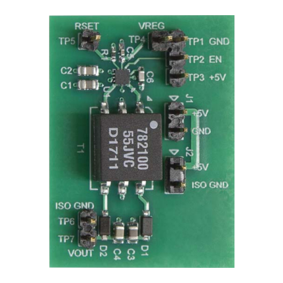
PE22100 UltraCMOS® Isolated Transformer Driver Evaluation Board Assembly Evaluation Board Assembly Overview The evaluation board (EVB) is assembled with a PE22100 transformer driver and a Murata 782100/55JVC transformer. The device is intended to be evaluated using the test pins shown in Figure Figure 1 •... -
Page 8: Block Diagram And Schematic
PE22100 UltraCMOS® Isolated Transformer Driver Block Diagram and Schematic The evaluation board block diagram and schematic are shown in Figure 2 Figure Figure 2 • PE22100 Evaluation Board Block Diagram 3.3V 100 nF Isolated 6.8V VREG OUTA 1:2.2 MBR0520 470 nF 3.3V 10 μF 0.1 μF... -
Page 9: Circuit Description
PE22100 UltraCMOS® Isolated Circuit Description The evaluation board is configured with a PE22100 transformer driver (U1) and a 782100/55JVC transformer (T1) in a push-pull configuration.The output from this transformer is then rectified via D1 and D2 to produce an isolated DC output. The PE22100 features an internal regulator that supplies the chip will output a nominal 2.6V on C5. - Page 10 PE22100 UltraCMOS® Isolated Transformer Driver This page intentionally left blank. Page 6 DOC-84193-1 – (06/2017) www.psemi.com...
-
Page 11: Quick Start Guide
PE22100 UltraCMOS® Isolated Transformer Driver Quick Start Guide Quick Start Overview This chapter will guide the user through the operating specifications, hardware configuration, and test setup. Operating the EVB beyond the operating specifications can result in damage to the high-speed driver and/or the transformer driver. -
Page 12: Evaluation Test Setup
PE22100 UltraCMOS® Isolated Transformer Driver Evaluation Test Setup Figure 5 shows the test setup for the PE22100 evaluation board. Make sure that the specified safety precau- tions mentioned in “Safety Precautions” on page 2 are followed. Figure 5 • PE22100 Evaluation Board Test Setup Supply PE22100 Reserved for... -
Page 13: Hardware Operation
PE22100 UltraCMOS® Isolated Hardware Operation The general guidelines for operating the hardware evaluation board are listed in this section. Follow the steps to configure the hardware properly for the performance. 1) Verify that all DC power supplies are turned off before proceeding. 2) Connect 5V to TP3 and ground return to TP1. - Page 14 PE22100 UltraCMOS® Isolated Transformer Driver This page intentionally left blank. Page 10 DOC-84193-1 – (06/2017) www.psemi.com...
-
Page 15: Technical Resources
PE22100 UltraCMOS® Isolated Transformer Driver Technical Resources Technical Resources Additional technical resources are available for download in the Products section at www.psemi.com. These include the Product Specification datasheet, evaluation kit schematic and bill of materials, material declaration form, and PC-compatible software file. Trademarks are subject to trademark claims. - Page 16 PE22100 UltraCMOS® Isolated Transformer Driver This page intentionally left blank. Page 12 DOC-84193-1 – (06/2017) www.psemi.com...
- Page 17 Mouser Electronics Authorized Distributor Click to View Pricing, Inventory, Delivery & Lifecycle Information: pSemi EK22100-01...
Need help?
Do you have a question about the UltraCMOS PE22100 and is the answer not in the manual?
Questions and answers