Advertisement
Quick Links
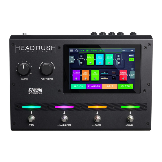
Footswitches
Knobs
Display
Connectors
Power
Dimensions
(width x depth x height)
Weight
SERVICE MANUAL
SPECIFICATIONS
(4) footswitches with color LEDs
(1) 300° master volume knob
(1) 360° navigation/data encoder
(1) full-color LED-backlit display with touch interface
6.9" / 176 mm (diagonal)
5.9" x 3.7" / 150 x 93 mm (width x height)
(1) 1/4" (6.35 mm) TS input (guitar)
(1) 1/4" (6.35 mm) TRS input (expression pedal)
(1) 1/4" (6.35 mm) TS input (expression pedal toe switch)
(1) 1/8" (3.5 mm) stereo input (auxiliary device)
(1) 1/4" (6.35 mm) TRS output (external amp switch)
(1) 1/4" (6.35 mm) TRS input (send)
(1) 1/4" (6.35 mm) TRS output (return)
(1) 5-pin MIDI input
(1) 5-pin MIDI output/thru
(1) USB Type-B port
(1) IEC power input
Connection DC power adapter input
Input Voltage 19 VDC, 3.42 A, center-positive
12.96" x 8.88" x 2.64"
32.92 x 22.56 x 6.71 cm
7.14 lbs.
3.24 kg
MODEL: GIGBOARD
Advertisement

Related Manuals for HEADRUSH GIGBOARD


Summary of Contents for HEADRUSH GIGBOARD
- Page 1 SERVICE MANUAL MODEL: GIGBOARD SPECIFICATIONS Footswitches (4) footswitches with color LEDs Knobs (1) 300° master volume knob (1) 360° navigation/data encoder Display (1) full-color LED-backlit display with touch interface 6.9” / 176 mm (diagonal) 5.9” x 3.7” / 150 x 93 mm (width x height) Connectors (1) 1/4”...
-
Page 2: Disassembly Procedure
DISASSEMBLY PROCEDURE DISASSEMBLE THE BOTTOM PANEL (A) REMOVE 6 PCS SCREW FROM THE TOP HOUSING.. (B) REMOVE 3 PCS SCREW FROM THE TOP HOUSING. (C) REMOVE 3 PCS SCREW FROM THE TOP HOUSING. (Fig1) DISASSEMBLE THE REAR PANEL PCB (A) REMOVE 3 PCS SCREW FROM THE REAR PANEL PCB ASS’Y. (B) REMOVE 9 PCS NUT FROM THE REAR PANEL PCB ASS’Y (Fig2) - Page 3 . DISASSEMBLE THE CARRIER BOARD PCB ASS’Y. (A)REMOVE 2 PCS SCREW FROM THE REAR PANEL PCB ASS’Y.. (B)REMOVE 2 PCS SCREW FROM THE CARRIER BOARD PCB ASS’Y. (Fig3) . DISASSEMBLE THE ADPTER PCB ASS’Y (A) REMOVE 2 PCS SCREW FROM THE ADPTER PCB ASS’Y. (Fig4)
- Page 4 DISASSEMBLE THE TOP PCB ASS’Y (A) REMOVE 2 PCS KNOB FROM THE VR PCB ASS’Y (B) REMOVE 2 PCS NUT FROM THE VR PCB ASS’Y (C) REMOVE 2 PCS WASHER FROM THE VR PCB ASS’Y (D) REMOVE 8 PCS SCREW FROM THE TOP PCB ASS’Y (E) REMOVE 5 PCS NUT FROM THE TOP PCB ASS’Y.
- Page 5 6. 6. 6. 6. DISASSEMBLE THE 7INCH CTP+TFT. (A) REMOVE 4 PCS SCREW FROM THE TOP HOUSING. (B) REMOVE 5 PCS SCREW FROM THE TOUCH PANEL HOLDER. (Fig6)
-
Page 6: Wiring Diagram
WIRING DIAGRAM (US/EU/UK/AUS/JIS/NZ/CCC/CA) -
Page 7: Packing Diagram
PACKING DIAGRAM (US/EU/UK/AUS/JIS/NZ/CCC/CA) -
Page 8: Explode Diagram
EXPLODE DIAGRAM (US/EU/UK/AUS/JIS/NZ/CCC/CA) EQUENCIAL NO EXPLODE DIAGRAM WILL BE MARKED ON REF.COLUMM OF BOM LIST... - Page 9 HG02MAO01 LEVEL DESCRIPTION HG02MAO01 GigBoard AC100~240V/60/50HZ(USA) AL9-79-075211 Carrier Board PCB Assembly(HG02) AL0-17-0102 RES ARRAY 4X1K AL2-49-0070 Diode BAV70 D4,D7,D11,D14,D20 AL2-51-0140 Schottky Barrier Rectifiers Diode B140-13-F SMA AL2-51-4401 Transistor 2N4401 NPN SOT-23 (Transistor 12 Q14,Q16~Q20,Q23,Q24,Q26~Q29 MMBT4401LT1 NPN SOT-23) AL2-51-4403 Transistor 2N4403 PNP SOT-23...
- Page 10 1F 0402 DIZDRCLAMP0524P Transient Voltage Suppressor Diode U55,U56 RCLAMP524PATCT QFN-10 DIZDSMA6J24CA Transient Voltage Suppressor Diode D1,C182 SMA6J24CA DIZDTPD2EUSB30A Transient Voltage Suppressor Diode U21,U29 TPD2EUSB30ADRTR SOT-3 ECS15725FLE ECAP 150UF/25V 8*10MM SMD Low ESR C126 ECS47650D Capacitor Electrolytic 47uf/50v D Type C172 EVA1704489 Rubber Foam Pad 5x20 (MS1-8)
- Page 11 RS010K10F03 RES 10K 1% SMD 0603 R23,R61,R63,R64,R66 RS010K16F02 RES 10K 1% SMD 0402 12 R14,R26,R53,R60,R69,R83,R114,R132,R148 R158,R159,R184 RS015K10F03 RES 15K 1% SMD 0603 RS015K16F02 RES 15K 1% SMD 0402 RS020010F03 RES 200 1% SMD 0603 R149 RS020K16F02 RES 20K 1% SMD 0402 R117 RS023716F02 RES 237 1% SMD 0402...
- Page 12 7Inch CTP+TFT Assembly PHG02MAO01 Pack Assembly AL7-51-1410-D Safety Manual AL7-91-1002 Gel Silica CGHG02310MAO01 Gift Box CTHG02513MAO01 Shipping Carton GEMAO12 Headrush Celestion Download Card GEMAO13 DRIVER Download Card OPHG02MAO01 Instuction Book PE150350BO Poly Bag 150*350mm PE230370402B07 Poly Bag 230*370mm PLHG0201 Polyfoam(LEFT) PLHG0202...
- Page 13 SC0310F2BBI Screw M3X10 HFB Tapping SPSAFSP065REBN2 Switching ADAPTOR 19V/3.42A UC/EU/UK TWAA812893J01 Footswitch Assembly CN0220000503 Flat Cable Multicolored 2P Pitch 2.0mm Dual Row Length 50mm Line/Female SWPB-24B-4 Switch Power Push Single Row TWPC17A02601 TOP PCB Assembly PC17A026 TOP PCB 2 Layer FR-4 312*165mm ENTEK TWPC17A026A01 TOP PCB Assembly CS101J5003NPO...
- Page 14 AL2-54-0138 Mosfet BSS138 N-CH SOT-23 AL2-61-7885 IC UA7805CKTTR Positive-Voltage Regulator TO-263 AL2-71-0072 IC TL072CDR Low-Noise Jfet-Input Operational Amplifiers Soic-8 AL4-00-0002 MIDI Jack 8P 90° Female J5,J6 CS100J5003NPO CCAP SMD 10pF/50V 5% 0603 NPO CS101J5003NPO CCAP SMD 100pF/50V 5% 0603 NPO 13 C45,C49,C58,C60,C61,C63,C65,C82,C87 C89,C90,C93,C94 CS101J5006NPO...
- Page 15 JK6K6J60A06E3K 6.3 Stero JACK 7P 90° DIP Female JKJY-3536L 3.5 phone Jack 5pin 90° JKK6J80LAA12E2K TRS Jack 13P 90° Female Dual J8,J12,J14,J20 MT11044128 Fixed Plate M1,M2,M3 PC17A027 REAR PANEL PCB 4-Layer FR-4 1.6T 186*96 RS000008J05 RES 0 5% SMD 0805 R65,R67,R70,R72,R76,R77,R102,R115,R123 RS000010J03 RES 0 5% SMD 0603...
- Page 16 SRHFD3-3 Relay HFD 3/3 K1,K2 TE612000202 Terminal 2P 2.0 180° TE612001201 Pin Header 180° Pitch:2.00mm Single Row 12P DIP TR2SD2704 TRANSISTOR 2SD2704 SOT-23 Q1,Q5,Q6,Q7,Q8,Q13,Q16,Q17,Q19 TRFDS4435BZ MOSFET P-chann FDS4435BZ SOIC-8 30r 8.8 UHBLM15AG102SN1 Inductor Bead 1000 200mA 0402 FB1~FB5 UHBLM18AG102SN1 BEAD 1000 100MHZ FB6~FB9 UHDRRI125-101M Inductor, 100UH±20% 1.3A SMD...
- Page 17 REV 1.03 HG02 Gigboard Test Procedure V1.03...
- Page 18 REV 1.03 Materials Needed: (1) Expression Pedal (1) Latching Sustain footswitch pedal (1) 1/4” TS male to 1/4” TS male cable (1) 1/4” TRS male to 1/4” TRS male cable (1) 1/4” TRS Y male to 2x RCA male cables (1) RCA female to 1/4”...
- Page 19 REV 1.03 Switch TEST Press each button and footswitch one at a time...
- Page 20 REV 1.03 Encoder TEST Rotate the large Encoder slowly first in a clockwise direction, then once the arrow has changed direction, rotate the encoder counter clockwise...
- Page 21 REV 1.03...
- Page 22 REV 1.03...
- Page 23 REV 1.03 TEST Rotate the pots one at a time first in a clockwise direction, then once the arrow has changed direction, rotate the pot counter clockwise. Move the expression pedal all the way forward (toe pressed down), and then all the way back (toe up/heel down) Materials Needed: (1) Expression Pedal cabling:...
- Page 24 REV 1.03...
- Page 25 REV 1.03...
- Page 26 REV 1.03...
- Page 27 REV 1.03...
- Page 28 REV 1.03 TEST Rotate the large Encoder slowly to cycle through all LED tests. The first test will light all LEDs white, the following tests will light each LED red, green, then blue. Confirm each color is lit per LED.
- Page 29 REV 1.03 Repeat for remaining LEDs...
- Page 30 REV 1.03 Display TEST Rotate the large Encoder slowly to cycle through all the display tests. The first test will fill the screen with all pixels white (check for any unlit pixels), the second test will turn all of the pixels black (check for any lit pixels), the third test will light the display with a gradient of colors at 100% brightness (check for any dim spots or color irregularities), the fourth test will light the display with a gradient of colors at 25% brightness (check for any bright spots or color irregularities)
- Page 31 REV 1.03...
- Page 32 REV 1.03...
- Page 33 REV 1.03 TEST Rotate the large Encoder slowly to cycle through all the CTP tests. The first test will have the tester place 5 fingers onto the display one at a time, then remove their fingers one at a time. The second test will have the tester touch all the yellow circles on the display.
- Page 34 REV 1.03...
- Page 35 REV 1.03 EXT AMP TEST – AMP T Test Materials Needed: (1) 1/4” TRS male to 1/8” TRS female adapter (1) 1/8” TRS male to RCA Y female adapter (1) RCA cable (1) RCA female to 1/4” TS adapter...
- Page 36 REV 1.03 TEST – AMP T Using a 1/4” TRS male to 1/8” TRS female adapter, 1/8” TRS male to RCA Y female adapter, RCA cable, and RCA female to 1/4” TS adapter, connect the 1/4” TRS male connector (of the 1/4” TRS to 1/8” TRS female adapter) to the HG03’s “EXT AMP”...
- Page 37 REV 1.03 TEST – AMP R Test Materials Needed: (1) 1/4” TRS male to 1/8” TRS female adapter (1) 1/8” TRS male to RCA Y female adapter (1) RCA cable (1) RCA female to 1/4” TS adapter...
- Page 38 REV 1.03 TEST – AMP R Using a 1/4” TRS male to 1/8” TRS female adapter, 1/8” TRS male to RCA Y female adapter, RCA cable, and RCA female to 1/4” TS adapter, connect the 1/4” TRS male connector (of the 1/4” TRS to 1/8” TRS female adapter) to the HG03’s “EXT AMP”...
- Page 39 REV 1.03 Device TEST Connect the USB 3 cable to the HG03, and 5 Pin MIDI cable from the MIDI Out/Thru to the MIDI In, and select “Start Test” Test 1 Materials Needed: (1) 5 Pin MIDI cable (1) USB 3 cable cabling: MIDI Out to MIDI In USB to host PC...
- Page 40 REV 1.03 Audio TEST 1 Materials Needed: (1) 1/4” TS male to 1/4” TS male cable cabling: TS FX Send to TS FX Return Setup HG03 Master knob: N/A TEST 2 Materials Needed: (1) 1/4” TS male to 1/4” TS male cable cabling: TS FX Send to TS Guitar In Setup...
- Page 41 REV 1.03 TEST 4 Materials Needed: (1) 1/4” TRS male to 1/4” TRS male cable cabling: TRS Out R to TRS FX Return Setup HG03 Master knob: N/A TEST 5 Materials Needed: (1) 1/4” TRS male to RCA male cable w/RCA to 1/4” TS adapters cabling: TRS Phones Out L to 1/4”...
- Page 42 REV 1.03 Audio Aux TEST Connect a CD player or MP3 player TRS out to the 1/8” Aux input and connect HG02’s Output TRS L to an external powered studio monitor, and HG02’s Output TRS R to an external powered studio monitor. Set the CD player/MP3 player’s volume to <=2Vrms (+6dBV) Test 1 Materials Needed:...
- Page 43 Set date and time and then press the “SET DATE/TIME” button and confirm that clock is correctly running. Version TEST Confirm the following Versions are listed correctly MIDI Controller FW Version: 01.00 (0100) Touch Panel FW Version: 0.0.3.0 AZ01 PCB Revision: RevG Extension PCB Hardware Revision: 2 HeadRush Gigboard Software Version: 1.0.0.4e03f2e Test App Version: 1.0.7...
- Page 44 REV 1.03 Serialization Connect the HG02 to a PC and run “HG02SerializationApp.exe” On HG02 select the “SERIAL” tab In the HG02SerializationApp select the “SYSTEM” tab Using a barcode scanner, scan the serial number into the Serialization App Once the serial has been entered select “PROGRAM” Confirm that the Serial Number is correct on the HG02...
- Page 45 HG02 Test Procedure v1.0.2: Clarified “Latching” footswitch to be used. Added to Materials Needed Updated Version Test software versions: MIDI Controller FW, Touch Panel FW, AZ01 PCB Rev, Extentension PCB Hardware Revision, HeadRusg Gigboard Software Version, and Test App Version Change List: HG02 Test Procedure v1.0.3:...
- Page 55 D B N u b t u j d E Y Q ! ) U N * ; ! !
- Page 56 D B N u b t u j d E Y Q ! ) U N * ; ! !
- Page 57 D B N u b t u j d E Y Q ! ) U N * ; ! !
- Page 58 D B N u b t u j d E Y Q ! ) U N * ; ! !
- Page 59 D B N u b t u j d E Y Q ! ) U N * ; ! !
- Page 60 D B N u b t u j d E Y Q ! ) U N * ; ! !
- Page 61 D B N u b t u j d E Y Q ! ) U N * ; ! !
- Page 62 D B N u b t u j d E Y Q ! ) U N * ; ! !
- Page 63 D B N u b t u j d E Y Q ! ) U N * ; ! !
- Page 64 D B N u b t u j d E Y Q ! ) U N * ; ! !
- Page 65 D B N u b t u j d E Y Q ! ) U N * ; ! !
- Page 66 D B N u b t u j d E Y Q ! ) U N * ; ! !
- Page 67 D B N u b t u j d E Y Q ! ) U N * ; ! !
- Page 68 D B N u b t u j d E Y Q ! ) U N * ; ! !
- Page 69 D B N u b t u j d E Y Q ! ) U N * ; ! !
- Page 70 D B N u b t u j d E Y Q ! ) U N * ; ! !
- Page 71 D B N u b t u j d E Y Q ! ) U N * ; ! !
- Page 72 D B N u b t u j d E Y Q ! ) U N * ; ! !
- Page 73 D B N u b t u j d E Y Q ! ) U N * ; ! !
- Page 74 D B N u b t u j d E Y Q ! ) U N * ; ! !
- Page 75 D B N u b t u j d E Y Q ! ) U N * ; ! !
- Page 76 D B N u b t u j d E Y Q ! ) U N * ; ! !
- Page 77 D B N u b t u j d E Y Q ! ) U N * ; ! !
- Page 78 D B N u b t u j d E Y Q ! ) U N * ; ! !
- Page 79 D B N u b t u j d E Y Q ! ) U N * ; ! !
- Page 80 D B N u b t u j d E Y Q ! ) U N * ; ! !
- Page 81 D B N u b t u j d E Y Q ! ) U N * ; ! !
- Page 82 D B N u b t u j d E Y Q ! ) U N * ; ! !
- Page 83 D B N u b t u j d E Y Q ! ) U N * ; ! !
- Page 84 D B N u b t u j d E Y Q ! ) U N * ; ! !
- Page 85 D B N u b t u j d E Y Q ! ) U N * ; ! !
Need help?
Do you have a question about the GIGBOARD and is the answer not in the manual?
Questions and answers