Table of Contents
Advertisement
Quick Links
Advertisement
Table of Contents

Related Manuals for Nortroll LineTroll 110Tmr

Summary of Contents for Nortroll LineTroll 110Tmr
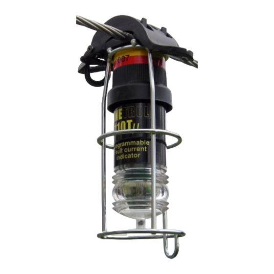
- Page 1 LineTroll 110Tµr User Manual...
-
Page 2: Table Of Contents
TABLE OF CONTENTS LINETROLL 110TµR OVERVIEW ............... 3 FUNCTIONAL DESCRIPTION ................3 2.1. Sensors ......................... 4 2.2. Activation criteria ....................... 4 2.3. Indication ........................4 2.4. Reset criteria ....................... 5 2.5. Battery lifetime / maintenance .................. 5 2.6. Low battery warning ....................5 2.7. -
Page 3: Linetroll 110Tµr Overview
Nortroll Collector device faults can be avoided. In this way the (CmT 115C or others). The Collector can be indicators can help to reduce wear and tear,... -
Page 4: Sensors
2.1. Sensors 2.2. Activation criteria The magnetic field generated by the line The LINETROLL 110Tr can be easily set current induces a signal in the indicators to operate in the wanted mode by altering a pickup coil. The induced signal is applied to number of switches inside the unit. -
Page 5: Reset Criteria
2.4. Reset criteria The indicator can be set to automatically resets in two different ways: 1) When the line is energised. The voltage or current sensor detects that the line is energised and can in turn reset the indicator after 30 seconds of continuously energised line 2) Automatic reset by internal timer. -
Page 6: Application
The LINETROLL-110T/r is suitable on: 3. APPLICATION 66-138kV Sub-Transmission & The application of LINETROLL 110Tµr Transmission networks. usually requires a preceding line survey so that the best use of the indicator may be Radial lines. identified. For the best economic benefit it is recom- ... -
Page 7: Application Notes
4. APPLICATION NOTES The aim of this section is to describe how the LINETROLL 110Tr indicator behaves for different service situations and network events. 4.1. Energising a healthy line Figure 6: Delayed reset of flashing. As the magnetising inrush current of a line can be very high, the indicator is provided with 5 seconds inrush blocking which 4.2. -
Page 8: Transient Faults
4.3. Transient faults 4.5. Multiple faults Multiple faults can sometimes occur. Transient faults cleared within the last Defective network components may burn or automatic reclosing, can be detected by the break due to the electro-dynamic force of a green LED. The green LED will flash for 24 fault current and cause a second fault. -
Page 9: Capacitive Discharges
4.6. Capacitive discharges To estimate the capacitive discharge current at any line point, you have to calculate the contribution from all the overhead lines and The LINETROLL-110Tr indicator is not underground cables lengths beyond that directional, it therefore detects current point only. -
Page 10: Programming
4.7. PROGRAMMING Switch Auto reset on return of voltage/current Programming the unit is done via a switch- bank on the printed circuit board. See fig. 9 ON * The indicator can be programmed to Table 5: Auto-Reset different current levels for either di/dt- * Note: If Auto-Reset = ON, then a sensing or threshold sensing. -
Page 11: Maintenance
LineTroll 110Tµr 5. MAINTENANCE It is advisable to inspect the indicator once a year or 1 year after it was last activated. The inspection should include a functional test with a magnet to show that the flash frequency and intensity are normal. 5.1. -
Page 12: Technical Specifications
7. TECHNICAL SPECIFICATIONS Indication: 1 Super intensive red Flash every 3 sec (10 Nominal voltage : 66-138 kV sec after 12 hours). Starting criteria : 1 green LED for transient fault Line energised for at least 5 seconds 1 amber/Yellow LED for battery warning followed by a stepped instantaneous Intensity: >... -
Page 13: Dimensions
2. Pull down, to release the indicator from the line. Figure 14Hot-stick mounting, - close to the traverse To fully cover all kinds of faults, NORTROLL recommend mounting indicators on all the phases in multi-phase networks. Locate the indicators at strategic points along the line. - Page 14 Test of the battery. Pull out the electronics board just as far as to enable operation of the switch-bank levers. Battery can be tested by placing a magnet on See Feil! Fant ikke referansekilden. 18. the yellow spot marked: RESET. Set the switches as required.
-
Page 15: Flashing Sequences
10. FLASHING SEQUENCES Transient fault: GREEN f=1/5 Hz f=1/10 Hz Comments: On transient fault, only the green LED will flash until timeout after 24h. The indicator is ready for a new fault within this 24 hour period. The red LED’s will NOT flash on transient fault. Permanent fault: GREEN f=1/3 Hz... - Page 16 Test & Reset The magnet must be kept at the yellow reset spot for minimum 2 sec to activate test or reset. Manual with magnet RESET Test sequence Manual with magnet Test sequence TEST-sequence; all 5 LED’s flashes in a rotating sequence LED flashes and a “Fault”...