Table of Contents
Advertisement
Quick Links
Advertisement
Table of Contents

Related Manuals for ITEM BL 1-04/C


Summary of Contents for ITEM BL 1-04/C
- Page 1 Controller BL 1-04 /C – 0.0.698.50 Product manual...
- Page 2 In the case of serious deviations from the user documentation, item has the right and the obligation to repair, unless it would involve an unreasonable effort.
-
Page 3: Table Of Contents
Controller BL 1-04 /C ― Product manual Table of Contents 1 1 About this Product manual ....................................5 1. 1 1. 1 ..Explanations and notation .................................5 1. 1 . 1 Structure of the warning notes ..............................5 1. 1 .2 Notation in this product manual..............................5 1.2 Additional documents ....................................6... - Page 4 Controller BL 1-04 /C ― Product manual 5 Fault messages........................................27 5. 1 Error management ....................................28 5.2 Error buffer ........................................ 30 6 Storage/transport ....................................... 31 7 Installation ........................................... 32 8 Technical data ........................................33 8. 1 General technical data .................................... 33 8.2 BL 1-04 /C: Power supply [X9] ................................
-
Page 5: 1 About This Product Manual
Controller BL 1-04 /C ― Product manual 1 About this Product manual The purpose of this Product manual is to ensure the safe use of the servo drives of the BL 1-04 /C series and of the item MotionSoft parameterisation software (abbreviated "iMS... -
Page 6: Additional Documents
Controller BL 1-04 /C ― Product manual 1.2 Additional documents Further information can be found in the following manuals: ▪ EtherCAT and CANopen manual Servo Positioning Controller C-Series:This manual describes the commissioning procedure for the servo drives C-Series or BL 1-04 /C with a CANopen or EtherCAT control system. -
Page 7: Applicable Standards
Controller BL 1-04 /C ― Product manual 1.4 Applicable standards Standard Description Safety of machinery - Safety-related parts of control systems - Part 1: General principles for EN 13849-1:2015 design Technical documentation for the assessment of electrical and electronic products with respect... -
Page 8: For Your Own Safety
Controller BL 1-04 /C ― Product manual 2 For your own safety 2.1 General information Servo drives of the BL 1-04 /C series can only be used safely if you read and comply with this document. The servo drive has a safe design. However, certain hazards exist in the context of certain activities. These hazards can be avoided by following the correct procedures. -
Page 9: Traget Group
Controller BL 1-04 /C ― Product manual 2.3 Target group Over its entire service life, work on the servo drive, with the exception of its operation, may only be performed by specialist per- sonnel and/or instructed persons who have been trained for the required tasks. The servo drive is to be operated by the user. -
Page 10: Personal Protective Equipment
Controller BL 1-04 /C ― Product manual 2.5 Personal protective equipment Always use personal protective equipment during the transport, installation, start-up, cleaning, maintenance and removal of the servo drive, for example: ▪ Protective gloves To prevent superficial hand injuries. -
Page 11: Protection Against Contact With Electrical Parts
Controller BL 1-04 /C ― Product manual Disconnect the electric equipment from the power supply via the main switch and secure it against reconnection. Wait until the DC bus has discharged in the following cases: ▪ maintenance and repairs ▪... -
Page 12: Protection Against Electric Shock By Way Of Protective Extra-Low Voltage (Pelv)
Controller BL 1-04 /C ― Product manual 2.8 Protection against electric shock by way of protective extra-low voltage (PELV) DANGER DANGER Dangerous electrical voltage! There is a risk of high electrical voltage due to incorrect electrical connections. Always follow the safety instructions stated hereinbelow. -
Page 13: Protection During The Handling And Installation Of The Devices
Controller BL 1-04 /C ― Product manual 2.11 Protection during the handling and installation of the devices CAUTION Risk of injury caused by crushing, shearing, cutting or impacts Improper handling and installation of certain parts will cause injuries. Always follow the safety instructions stated hereinbelow. -
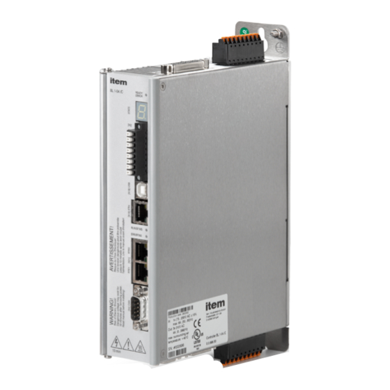
Page 14: Device View
Controller BL 1-04 /C ― Product manual 3.2 Device view Front view Product name Earthing screw Status indicator LED (READY, ERROR, ENABLE) Seven-segment status indicator [X3] STO interface (STOA, STOB), Limit switch (DIN6, DIN7), Dig. output (DOUT0) [X19] USB interface... -
Page 15: Features
Integrated fieldbus interfaces ▪ CANopen interface for the integration in automation systems ▪ EtherCAT interface (CoE) ▪ ProfiNet interface (Item standard telegrams, based on PROFIdrive) Integrated universal shaft encoder evaluation for the following encoder types: ▪ Resolvers ▪ Analogue and digital incremental encoders with and without commutation signals ▪... -
Page 16: Sto (Safe Torque Off)
The purpose of this chapter is to ensure the safe use of the STO (safe torque off) safety function that is integrated in the servo drive. This documentation refers to the following versions: ▪ Controller BL 1-04 /C with the STO function, revision 1.0 or higher ▪ item MotionSoft parameterisation program version 3.0 or higher. -
Page 17: Special Safety Instructions
Controller BL 1-04 /C ― Product manual 4.1 Special safety instructions DANGER Dangerous electrical voltage! Always follow the safety instructions for electric drives and control systems in section 2. For your own safety on page 8. WARNING Hazards due to the loss of the safety function If you do not comply with the specified ambient and connection conditions, the safety function will be lost. -
Page 18: Qualification Of The Specialist Personnel (Personnel Requirements)
Controller BL 1-04 /C ― Product manual 4.3.1 Qualification of the specialist personnel (personnel requirements) The device may only be set into operation by a qualified electrical technician who is familiar with: ▪ the installation and operation of electrical control systems ▪... -
Page 19: Description Of The Sto Safety Function
Controller BL 1-04 /C ― Product manual 4.5.1 Description of the STO safety function Use the "Safe Torque Off" (STO) function if you need to disconnect the motor safely from the energy supply for your applica- tion. The "Safe Torque Off" function switches off the driver supply for the power semiconductors. This prevents the power output stage from providing the voltage that is required by the motor. -
Page 20: Overview Of The [X3] Interface
Controller BL 1-04 /C ― Product manual 4.5.2 Overview of the [X3] interface Figure 5: Position of connector X3 At its front, the servo drive has an 8-pin connector [X3] for ▪ the STO control inputs, ▪ the digital output DOUT0, and ▪... -
Page 21: Discrepancy Time
Controller BL 1-04 /C ― Product manual to the safe state (STO) and for the tolerance time with regard to the OSSD signals (buffer time). These values depend on the input voltage. The time response is described in section 8. 1 1.2 Time response on page 48. -
Page 22: Circuit Examples
Controller BL 1-04 /C ― Product manual INFO Acknowledgement of error messages When error messages are acknowledged, all of the acknowledgeable errors concerning the functional safety technology will also be acknowledged at the same time. See section 4. 1 1 Diagnostics and fault clearance on page 27. -
Page 23: Safe Torque Off (Sto)
Controller BL 1-04 /C ― Product manual 4.6.1 Safe torque off (STO) Servo drive with an integ- 24V DC rated STO function (only 0V DC the relevant connections are shown) Emergency stop button Safety gate Light grid Safety relay... -
Page 24: Deceleration And Safe Torque Switch Off(Ss1, "Safe Stop 1")
Controller BL 1-04 /C ― Product manual 4.6.2 Deceleration and safe torque switch off (SS1, "Safe Stop 1") Servo drive with an integ- 24V DC rated STO function (only 0V DC the relevant connect ions are shown) X1, DIN5... -
Page 25: Prior To Commissioning
Controller BL 1-04 /C ― Product manual assumed that cross-circuit and earth faults between the individual wires are excluded (acceptance inspection of the control cabinet for correct wiring). ▪ The circuit example has a two-channel structure that is suitable for category 3 and, if additional measures are implemented, also for category 4. -
Page 26: Status Indication Of The Finite State Machine
The status of the internal finite state machine is also indicated in the window Safety module (integrated). 4.8.3 "Safety module (integrated)" window The window Safety module (integrated) can be opened as follows in item MotionSoft ® Figure 10: "Safety module (integrated)" window The window shows the status data of the integrated STO safety function. -
Page 27: Functional Test, Validation
Controller BL 1-04 /C ― Product manual The window has several areas: The first three LEDs indicate the status of the functional safety system in the servo drive firmware as it has been recognised by the finite state machine of the servo drive. -
Page 28: Error Management
2. Error elimination: Eliminate the cause of the error in compliance with the safety instructions (section 2.4 General safety instructions on page 9). 3. Error acknowledgement: Clear the error by clicking the button Clear in the item MotionSoft error window. Alternatively, the ®... - Page 29 Controller BL 1-04 /C ― Product manual Figure 12: "Error management" window You can use this window to define the reaction of the servo drive in the event of an error. Different responses can be assigned to every individual group. First select the group (by clicking) and then assign the responses. The following list shows the responses with a rising priority.
-
Page 30: Error Buffer
Controller BL 1-04 /C ― Product manual 5.2 Error buffer Error/Error buffer The Error buffer window shows all of the errors, warnings and events that have occurred since the last activation. The following information is provided: ▪ Error number ▪... -
Page 31: Storage/Transport
Controller BL 1-04 /C ― Product manual 6 Storage/transport The following requirements must be fulfilled for the storage and transport of the servo drive: Storage ▪ Store the servo drive in line with the specified storage temperatures. Use only its original packaging. -
Page 32: Installation
Controller BL 1-04 /C ― Product manual 7 Installation R 2,5 mm 25 mm R 5 mm R 2,5 mm 25 mm 50 mm Figure 14: Servo drive BL 1-04 /C The following requirements must be fulfilled for the installation of the servo drive: ▪... -
Page 33: Technical Data
Controller BL 1-04 /C ― Product manual ▪ The BL 1-04 /C servo drives have fastening tabs at the top and bottom. These tabs are used to mount the servo drive ver- tically to a control cabinet plate with two M5 screws. Recommended tightening torque for an M5 screw of property class 5.6: 2.8 Nm. -
Page 34: Bl 1-04 /C: Power Supply [X9]
Controller BL 1-04 /C ― Product manual Dimensions and weight*) Characteristic Value Dimensions including the mounting plate (H * W * D) 245 mm * 50 mm * 163 mm Housing dimensions (H * W * D) 200 mm * 50 mm * 163 mm Weight approx. -
Page 35: Bl 1-04 /C: Motor Connector [X6]
Controller BL 1-04 /C ― Product manual External braking resistor Characteristic Value Braking resistor ≥ 75 Ω Nominal power ≥ 8 kW Peak power ≥ 2,5 W INFO Additional information The external braking resistor must be connected in parallel to the internal braking resistor. As a result, the continuous power and pulse power can be doubled if a 75 Ω... - Page 36 Controller BL 1-04 /C ― Product manual PWM frequency f BL 1-04 /C nenn 10 kHz 12 A 16 kHz *) The PWM frequency is the reciprocal of half of the current controller cycle time ti. The variable cycle times enable particularly high dynamics combined with reduced power data.
- Page 37 Controller BL 1-04 /C ― Product manual Characteristic Value Sensor type Analogue Silicon temperature sensor PTC/NTC, Sensor type e.g. KTY84-130 or similar Linear/non-linear, parameterisable (10 nodes) Linear/non-linear, parameterisable (10 nodes) Measuring range from 300 Ω to 20 kΩ (+-10%)
-
Page 38: Resolver Connector [X2A]
Controller BL 1-04 /C ― Product manual 8.4 Resolver connector [X2A] Characteristic Value Transformation ratio 1:2 to 1:4 Carrier frequency 5-10 kHz Excitation voltage 5-6 Veff, short-circuit-proof Excitation impedance (at 10 kHz) 4 Ω Stator impedance > 30 Ω... - Page 39 Controller BL 1-04 /C ― Product manual Digital incremental encoders Digital incremental encoders with RS422-compatible A/B/N signals with a line count of up to 16,384 lines can be connected (e.g. ERN 420). In addition, Hall generator signals with a TTL level for determining the commutation position can also be connected.
- Page 40 Controller BL 1-04 /C ― Product manual HIPERFACE encoders ® Shaft encoders with HIPERFACE made by Sick-Stegmann are supported in the single- turn and multi-turn variants. The follow- ® ing encoder models can be connected: ▪ Single-turn SinCos encoders: SCS 60/70, SKS 36, SRS 50/60/64, SEK 34/37/52 ▪...
-
Page 41: Usb [X19]
Controller BL 1-04 /C ― Product manual 8.6 USB [X19] Communication interface Value Function USB 2.0, USB-B, slave–client, Connector type USB-B Current consumption None (self-powered) Protocol item-specific (generic device) 8.7 Standard Ethernet [X18] Communication interface Value Function Ethernet, 10/100 Mbaud, UDP communication... -
Page 42: Can Bus [X4]
Controller BL 1-04 /C ― Product manual 8.9 CAN bus [X4] Communication interface Value Standard ISO/DIS 11898-2, CAN 2 0A Baud rates 50, 100, 125, 250, 500, 1000 kBit/s Protocol CANopen, as per DS301 and DSP402 8.10 I/O Interface [X1] Servo drives of the BL 4000-C series have 3 digital outputs (DOUT), 9 digital inputs (DIN) and 2 analogue inputs (AIN). - Page 43 Controller BL 1-04 /C ― Product manual Analogue input AIN0 Characteristic Value Input range ± 10 V Resolution 12 Bit Filter time configurable: 2 x t to 200 ms *) t corresponds to the configurable current controller cycle time...
-
Page 44: Time Response Of The Digital Inputs
Controller BL 1-04 /C ― Product manual Master frequency output X1 The connector X1 also accommodates the master frequency output (encoder emulation). To use this function, X1 must be configured as the master frequency output. Characteristic Value Number of lines... -
Page 45: Time Response Of The Digital Outputs
Controller BL 1-04 /C ― Product manual Parameter Max. Maximum delay until the start of a position 5 • t set becomes active t start Current rise time (with current feedforward control) = position controller cycle time (typically 200 µs with a current controller cycle time ti of 50 µs) = speed controller cycle time (typically 100 µs with a current controller cycle time ti of 50 µs) -
Page 46: Time Response During Power On
Controller BL 1-04 /C ― Product manual 8.10.3 Time response during power ON 24V power on mains ready to enable drive enable output stage on (PWM active) holding brake released velocity boot Noff Figure 17: Time diagram of the servo drive Parameter Min. -
Page 47: Sto [X3]
Controller BL 1-04 /C ― Product manual 8.11 STO [X3] Characteristic values Characteristic Value Safety level Category 4 and performance level e or SIL3/SIL CL3. PFH(Probability of dange- 3 x 10 –11 rous Failure per Hour) PFD (Probability of dange-... -
Page 48: Time Response
Controller BL 1-04 /C ― Product manual Response time until power output stage inactive and maximum OSSD test pulse duration Characteristic Value Input voltage (STOA/STOB) 19.2 V 24 V 28.8 V Typical response time 2 ms 3 ms 4 ms Max. - Page 49 Controller BL 1-04 /C ― Product manual STOA STOB driver supply +5V_OS driver supply +5V_US „Safe Torque Off“ (STO) active „H“ is displayed „H“ wird angezeigt holding brake (optional) velocity Ext. drive enable STOA/B OFF STOA/B OFF STOA/B ON...
-
Page 50: Time Response Of The Ss1 Activation During Operation With A Restart
Controller BL 1-04 /C ― Product manual 8.11.2.2 Time response of the SS1 activation during operation with a restart The time response is based on the SS1 example circuit in section 4.6.2 Deceleration and safe torque switch off(SS1, "Safe Stop 1") on page 24. -
Page 51: Microsd Card
Controller BL 1-04 /C ― Product manual Time Description Value Delay between the switching of S1 and the See the data sheet of the safety relay closing of the undelayed contact K1 Delay between S1 and the opening of the... -
Page 52: Electrical Installation
Controller BL 1-04 /C ― Product manual 9 Electrical installation This chapter provides all of the relevant information for the electrical installation of a servo drive of the BL 4000-C series with an integrated "Safe Torque Off (STO)" safety function. -
Page 53: Operation With Long Motor Cables
Controller BL 1-04 /C ― Product manual ▪ The earthing (grounding) screw of the mounting plate (see section 3.2 Device view on page 14) must also be connected to the mains-side PE connector via a separate earth lead. ▪ The cross-section of each earth lead must not be smaller than the cross-section of the supply leads (L/N or L1-L3). -
Page 54: Additional Requirements For The Ul Approval
Controller BL 1-04 /C ― Product manual 9.2 Additional requirements for the UL approval Mains power supply protection Integral solid state short circuit protection does not provide branch circuit protection. Branch circuit protection must be provid- ed in accordance with the Manufacturer Instructions, National Electrical Code and any additional local codes. - Page 55 Controller BL 1-04 /C ― Product manual First, wire the servo drive completely. Then, switch on the 24 V supply and the mains power supply. Configuration on the device [X9] Weidmüller SL 5.08HC/09/90G 3.2SN BK BX Mating connector [X9] Weidmüller BLF 5.08HC/09/180 SN BK BX...
-
Page 56: Bl 4300-C: Connector: Power Supply [X9], [X9A], [X9B]
Controller BL 1-04 /C ― Product manual LAPP KABEL ÖLFLEX CLASSIC 110 Device type Cable type Specification (L, N, PE) Circuit breaker BL 4102-C 3 G 1.0 3 x 1,0 mm² (AWG 18) B 10 BL 4104-C 3 G 1.0 3 x 1,0 mm²... - Page 57 Controller BL 1-04 /C ― Product manual Pin assignment: motor with HIPERFACE DSL ® WEIDMÜLLER Pin assignment: motor with Hiperface DSL ® BLF 5.08HC/09/180 SN BK BX MT + MT - / DSL - DSL + BR + BR -...
- Page 58 Controller BL 1-04 /C ― Product manual An existing holding brake in the motor must be connected to the terminals BR+ and BR-. Please note the maximum output current that is provided by the servo drive. DANGER Dangerous electrical voltage! The signals for the temperature sensor "MT-"...
-
Page 59: Bl 4300-C: Connector: Motor [X6], [X6A]
Controller BL 1-04 /C ― Product manual ▪ The outer shield is always connected to PE (connector housing) on the servo drive side. ▪ The three inner shields are connected to PIN 3 of X2A on one side of the servo drive. - Page 60 Controller BL 1-04 /C ― Product manual It is also possible to evaluate an optional error signal (AS/NAS) via pin 6. With some incremental encoders, it is possible to detect and signal soiling or other faults/malfunctions of the measuring system via an output (AS or NAS). The error signal can be evaluated by digital as well as analogue incremental encoders.
- Page 61 Controller BL 1-04 /C ― Product manual Name Specification Motor temperature sensor, normally closed contact, PTC, NTC, KTY U_SENS+ Sensor cables for the encoder supply. In case of long cables, connect to US/GND at the motor end. U_SENS- Operating voltage for incremental encoders...
- Page 62 Controller BL 1-04 /C ― Product manual Name Specification Motor temperature sensor, normally closed contact, PTC, NTC, KTY U_SENS+ Sensor cables for the encoder supply. In case of long cables, connect to US/GND at the motor end. U_SENS- Operating voltage...
-
Page 63: Connector: Usb [X19]
Controller BL 1-04 /C ― Product manual Name Specification Motor temperature sensor, normally closed contact, PTC, NTC, KTY U_SENS+ Sensor cables for the encoder supply. In case of a long cable, connect to US/GND at the motor end. U_SENS-... -
Page 64: Connector: Standard Ethernet [X18]
Controller BL 1-04 /C ― Product manual In case of non-EMC-compliant wiring of the servo drive and motor, compensating electric current may flow via the connected computer and the USB interface. This may lead to communication problems. To avoid this, we recommend using an electrically isolated USB adapter "Delock USB Isolator" (type 62588 by Delock) or a comparable adapter. -
Page 65: Connector: Real-Time Ethernet [X21]
Controller BL 1-04 /C ― Product manual Cat.6 patch cable RJ45 LAN cable S-FTP/PIMF. Figure 29: Pin assignment of the network connector Name Description Colour Transmission signal + Yellow Transmission signal - Orange Reception signal + White Reception signal - Blue 9.9 Connector: real-time Ethernet [X21]... -
Page 66: Connector: Can Bus [X4]
In order to keep interferences as low as possible ensure that ▪ the motor cables are not installed parallel to signal lines ▪ the motor cables comply with the Item specification ▪ the motor cables are properly shielded and earthed (grounded) -
Page 67: Connector: I/O Interface [X1]
Controller BL 1-04 /C ― Product manual Steckerbelegung [X4] Name Specification Not used CAN-GND, directly coupled to GND in the servo drive CANL CAN low signal line CANH CAN high signal line See pin no. 6 Not used Not used... - Page 68 Controller BL 1-04 /C ― Product manual For optimal interference suppression on the analogue signal lines, the cores for the analogue signal must be shielded sepa- rately. It may be useful to run the analogue signal in a separate, shielded cable.
- Page 69 Controller BL 1-04 /C ― Product manual Pin assignment [X1] Name Specification #AIN1 Analogue input 1, input voltage 30 V max. AIN1 #AIN0 Analogue input 0, input voltage 30 V max. AIN0 A / CLK Incremental encoder signal A/stepper motor signal CLK...
-
Page 70: Connector: Sto [X3]
Controller BL 1-04 /C ― Product manual Cable type and configuration [X1] The cable name that is stated refers to a cable made by Lapp. However, it is also possible to use comparable cables from other manufacturers, for example Lütze or Helukabel. -
Page 71: Maintenance, Cleaning, Repair And Disposal
Controller BL 1-04 /C ― Product manual Cable type and configuration [X3] Characteristic Value Max. cable length, unshielded 30 m Max. cable length, shielded > 30 m In the case of wiring outside the control cabinet and with cable lengths > 30 m, Shielding the shield must be led into the control cabinet. - Page 72 Controller BL 1-04 /C ― Product manual Disposal, removal, decommissioning, replacement DANGER Dangerous electrical voltage! Following the instructions stated hereinbelow to ensure the safe decommissioning of the servo drive. ▪ Switch the power supply completely off. ▪ Disconnect the mains power connectors.
-
Page 73: Appendix
Controller BL 1-04 /C ― Product manual 11 Appendix 11.1 CE conformity (EMC, RoHS, Low Voltage Directive) -
Page 74: Ce Conformity (Machinery Directive)
Controller BL 1-04 /C ― Product manual 11.2 CE conformity (Machinery Directive) -
Page 75: Culus Certification
Controller BL 1-04 /C ― Product manual 11.3 cULus certification C E R T I F I C A T E O F C O M P L I A N C E E475045 Certificate Number E475045-20160413 Report Reference... - Page 76 Controller BL 1-04 /C ― Product manual C E R T I F I C A T E O F C O M P L I A N C E E475045 Certificate Number E475045-20160413 Report Reference 2020-NOVEMBER-17 Issue Date This is to certify that representative samples of the product as specified on this certificate were tested according to the current UL requirements.
-
Page 77: Safety Technology Glossary
Controller BL 1-04 /C ― Product manual 11.4 Safety technology glossary Term/abbreviation Description Common cause failure in accordance with EN ISO 13849-1 DC avg Average diagnostic coverage in accordance with IEC 61508 and EN 61800-5-2. Hardware fault tolerance in accordance with IEC 61508. - Page 78 Controller BL 1-04 /C ― Product manual 11.5 Risk reduction questions Questions for a validation in accordance with EN ISO 12100- 1:2010 (example) Question Yes / No Completed Have all of the operating conditions and interventions been taken into account? Has the "3-step method"...
- Page 79 Controller BL 1-04 /C ― Product manual Questions for a validation in accordance with EN ISO 13849-1 and -2 (example) Questions Yes / No Completed Has a risk assessment been conducted? Have an error list and a validation plan been drawn up?
-
Page 80: Error Messages And Warnings
Controller BL 1-04 /C ― Product manual 11.6 Error messages and warnings Group 0: Events An invalid (corrupted) entry in the error buffer has been marked with this error number. Entry in the permanent event memory. No measures required. - Page 81 Controller BL 1-04 /C ― Product manual Group 3: Overtemperature motor Motor overtemperature Motor too hot? Check the parameterisation. Correct sensor? Sensor defective? (analogue) Check the parameterisation of the sensor or the sensor characteristics. If the Motor overtemperature error still occurs after the sensor has been bypassed, replace the servo drive.
- Page 82 Controller BL 1-04 /C ― Product manual Group 7: Overvoltage Check the connection to the braking resistor (internal/external). Is the external Overvoltage DC bus circuit braking resistor overloaded? Check the rating. Disconnect the device immediately from the mains power supply and check the vol- Overvoltage at power input tage at the main power input.
- Page 83 Controller BL 1-04 /C ― Product manual Encoder EEPROM is write Please contact the Technical Support team. protected Too small memory size of Please contact the Technical Support team. encoder EEPROM Group 10: Motor overspeed protection Overspeed (motor over- 10-0 Check the offset angle.
- Page 84 Controller BL 1-04 /C ― Product manual Group 13: Timeout CAN-Bus 13-0 Timeout CAN bus Check the CAN parameterisation. Group 14: Motor and resolver identification Insufficient DC bus circuit 14-0 Check the power supply voltage. Check the motor resistance.
- Page 85 Controller BL 1-04 /C ― Product manual Group 17: Max. following error exceeded Max. following error 17-0 Increase the error window. Decrease the acceleration. exceeded Encoder difference External angle encoder not connected or defective? The deviation fluctuates, 17-1 monitoring e.g.
- Page 86 Controller BL 1-04 /C ― Product manual Group 24: Analogue input monitoring Analogue input above maxi- 24-0 Check the parameterisation of the maximum limit. Check the wiring. mum limit Analogue input below mini- 24-1 Check the parameterisation of the minimum limit. Check the wiring.
- Page 87 Controller BL 1-04 /C ― Product manual Group 28: Operating hours meter 28-0 Missing operating hours meter Please contact the Technical Support team. Operating hours meter: 28-1 write error Operating hours meter 28-2 corrected Acknowledge the error. If the error recurs, contact the Technical Support team.
- Page 88 Controller BL 1-04 /C ― Product manual Discharging period DC bus Bridge for the internal braking resistor installed?Check the connection of the 32-6 circuit exceeded external braking resistor. Please contact the Technical Support team. Supply voltage missing for 32-7 No DC bus voltage.
- Page 89 Controller BL 1-04 /C ― Product manual Sercos: unknown operation 37-5 Check the settings for the operating modes in the IDNs S-0-0032 to S-0-0035. mode selected 37-6 Sercos: T3 invalid Increase the baud rate. Shift T3 manually. Sercos III: communication 37-7 Please contact the Technical Support team.
- Page 90 Controller BL 1-04 /C ― Product manual Group 40: SW limit switches Negative SW limit switch 40-0 reached Check the permissible positioning range. Positive SW limit switch 40-1 reached Target position beyond the The start of a positioning run has been suppressed, since the target is located...
- Page 91 Controller BL 1-04 /C ― Product manual Group 44: CAM disc Check whether the index has been assigned correctly. 44-0 CAM table error Check whether there are cam discs present in the device. Ensure that the drive has been homed prior to the activation of the cam disc.
- Page 92 Controller BL 1-04 /C ― Product manual Group 51: FSM 2.0 Cause: No safety module detected or unknown module type. ▪ Measure: ▪ Install a safety module or fieldbus activation module that is suitable for the firmware and hardware.
- Page 93 Controller BL 1-04 /C ― Product manual Cause: Internal hardware error (brake activation control signals) of the safety module or fieldbus activation module. Measure: FSM: error in brake 51-5 Module presumably defective. If possible, replace with another module. activation Cause: Error in brake driver circuit section in the servo drive.
- Page 94 Controller BL 1-04 /C ― Product manual Cause: Servo drive reports error if the currently requested direction of movement is not possible because the safety module has blocked the setpoint value in this direction. Error may occur in connection with the SSFx safe speed functions if an asymme-...
- Page 95 Controller BL 1-04 /C ― Product manual Group 54: FSM: Violation of safety conditions Cause: Brake should engage; no feedback received within the expected time. Measure: ▪ Check how the feedback signal is configured – was the correct input selected...
- Page 96 Controller BL 1-04 /C ― Product manual Cause: Actual speed outside permitted limits for too long. Measure: Check when the violation of the safety condition occurs: a) During dynamic braking to zero. b) After the drive has reached zero speed.
- Page 97 Controller BL 1-04 /C ― Product manual Group 55: FSM: Actual value evaluation 1 Cause: • Subsequent error when a position encoder fails. FSM: no actual speed / position value available or 55-0 • Safety function SSF, SS1, SS2 or SOS requested and actual rotational standstill for >...
- Page 98 Controller BL 1-04 /C ― Product manual Cause: ▪ Error in connected position encoder. ▪ EMC malfunctions affecting the position encoder. ▪ Impermissibly high acceleration rates in the movement profiles. ▪ Acceleration limit parameterised too low. ▪ Angle jump after homing run in the position data transmitted from the servo drive to the safety module.
- Page 99 Controller BL 1-04 /C ― Product manual Group 57: FSM: Inputs/Outputs Cause: ▪ Internal error of digital inputs DIN40 ... DIN43 (detected via internal test signals). ▪ Error at brake output at X6 (signalling, detected by test pulses). ▪ Internal error of brake output (detected via internal test signals).
- Page 100 Controller BL 1-04 /C ― Product manual Cause: ▪ The safety module‘s temperature monitor has been triggered; the temperatu- re of μC1 or μC2 was below -20° or above +75°C. Measure: 57-6 FSM: overtemperature ▪ Check the operating conditions (ambient temperature, control cabinet tempe- rature, installation situation in the control cabinet).
- Page 101 Controller BL 1-04 /C ― Product manual Cause: Timeout during cross-comparison (no data) or cross-comparison faulty (data for μC1 and μC2 are different). ▪ Error in cross-comparison for digital I/O. ▪ Error in cross-comparison for analogue input. ▪ Error in cross-comparison for internal operating voltage measurement (5 V, 3.3 V, 24 V) and reference voltage (2.5 V).
- Page 102 Controller BL 1-04 /C ― Product manual Cause: Too many errors have occurred simultaneously. Measure: ▪ Clarify: What is the status of the inserted safety module - does it contain a valid parameter set? ▪ Read out and analyse the permanent event memory of the servo drive via the parameterisation program.
- Page 103 Controller BL 1-04 /C ― Product manual Group 62: EtherCAT 62-0 EtherCAT: general bus error There is no EtherCAT bus. Check the wiring. Replace the technology module. 62-1 EtherCAT: initialisation error Please contact the Technical Support team. Is the protocol incorrect (no CAN over EtherCAT)?
- Page 104 Controller BL 1-04 /C ― Product manual Group 65: DeviceNet DeviceNet active, but no 65-0 Deactivate the DeviceNet communication or insert a module. module 65-1 Timeout I/O Connection An I/O message has not been received within the expected time.
- Page 105 Controller BL 1-04 /C ― Product manual Group 72: PROFINET PROFINET: initialisation 72-0 Replace the PROFINET module. error Communication is not possible, e.g. because the bus cable has been disconnec- 72-1 PROFINET: bus error ted. Check the wiring and restart the PROFINET communication.
- Page 106 Controller BL 1-04 /C ― Product manual Group 81: IRQ_4_5 81-4 Time overflow low-level IRQ Please contact the Technical Support team. Group 82: Internal sequence control Internal sequence control: The process was aborted. 82-0 Sequence control+ For information only. No measures required.
- Page 107 Controller BL 1-04 /C ― Product manual Group 90: HW initialisation Missing hardware 90-0 component (SRAM) Missing hardware 90-1 component (FLASH) Error during booting of 90-2 FPGA Error during start of SD- 90-3 ADUs Synchronisation error SD- Please contact the Technical Support team.
- Page 108 Industrietechnik GmbH Friedenstrasse 107-109 42699 Solingen Germany Phone +49 212 6580 0 +49 212 6580 310 info@item24.com item24.com...
Need help?
Do you have a question about the BL 1-04/C and is the answer not in the manual?
Questions and answers