Table of Contents
Advertisement
Quick Links
Advertisement
Table of Contents

Related Manuals for ITEM C 3-Series


Summary of Contents for ITEM C 3-Series
- Page 1 Product Manual item Servo Positioning Controller C 3-Series designed for Functional Safety item Industrietechnik GmbH Telephone: +49-(0)212-6580-0 Friedenstraße 107-109 Fax: +49-(0)212-6580-310 42699 Solingen E-mail: info@item24.com ://www.item24.com Germany http...
- Page 2 systems.
- Page 3 Revision Information Author: item Industrietechnik GmbH Product Manual „item Servo Positioning Controller C 3-Series“ Manual title: File name: P-HB_item Steuerung_C3_5p0_EN_bearbeitet.docx Version 5.0 November 2016 Page 3...
-
Page 4: Table Of Contents
TABLE OF CONTENTS: GENERAL ......................15 Documentation ....................15 Scope of supply ..................... 16 SAFETY NOTES FOR ELECTRICAL DRIVES AND CONTROLLERS ........17 Symbols....................... 17 General notes ....................18 Hazards resulting from misuse................20 Safety instructions ..................21 2.4.1 General safety instructions ..............21 2.4.2 Safety notes for assembly and maintenance ........... - Page 5 FUNCTION OVERVIEW ..................... 52 Motors ......................52 5.1.1 Synchronous servomotors ..............52 5.1.2 Linear motors ................. 52 Functions of the item Servo Positioning Controller C 3-Series ........53 5.2.1 Compatibility .................. 53 5.2.2 Pulse width modulation (PWM) ............53 5.2.3 Setpoint management ..............
- Page 6 FSM 2.0 – STO (Safe Torque Off) ............68 MECHANICAL INSTALLATION ................... 69 Important notes ..................... 69 Device view ....................71 Installation....................73 ELECTRICAL INSTALLATION ..................74 Connector configuration .................. 74 item C 3-Series – complete system ..............75 Connector: power supply [X9] ................77 Page 6...
- Page 7 8.3.1 Configuration on the device [X9]............77 8.3.2 Mating connector [X9] ..............77 8.3.3 Pin assignment [X9] ................. 78 8.3.4 Cable type and configuration [X9] ............78 8.3.5 Connection notes [X9] ..............79 Connector: motor [X6] ..................80 8.4.1 Configuration on the device [X6]............80 8.4.2 Mating connector [X6] ..............
- Page 8 8.8.4 Cable type and configuration [X10] ............97 8.8.5 Connection notes [X10] ..............97 Connector: incremental encoder output [X11] ............98 8.9.1 Configuration on the device [X11] ............98 8.9.2 Mating connector [X11] ..............98 8.9.3 Pin assignment [X11] ............... 98 8.9.4 Cable type and configuration [X11] ............
- Page 9 10.2 Tools/material ..................... 114 10.3 Connecting the motor ..................114 10.4 Connecting the item Servo Positioning Controller C 3-Series to the power supply ..115 10.5 Connecting the PC (serial interface) ..............115 10.6 Connecting the PC (USB interface, alternative) ............. 115 10.7 Operability check ..................
- Page 10 11.1.11 Operating hours counter ..............118 11.2 Operating mode and error messages ..............119 11.2.1 Operating mode and error indication ..........119 11.2.2 Error messages ................120 TECHNOLOGY MODULES ..................153 12.1 PROFIBUS-DP interface ................. 153 12.1.1 Product description ................ 153 12.1.2 Technical data ................
- Page 11 Servo Positioning Controller C 3-Series: mounting plate ............73 Figure 13: Connection to the power supply and motor ................74 Figure 14: Complete set-up of the item C 3-Series with a motor and PC ............76 Figure 15: Power supply [X9] ......................79 Figure 16: Motor connector [X6] ......................81...
- Page 12 Figure 33: Servo positioning controller with an integrated technology module ..........160 Page 12...
- Page 13 Table of Tables: Table 1: Scope of supply .........................16 Table 2: Connector set: POWER connector ..................16 Table 3: Connector set: DSUB connector .....................16 Table 4: Connector set: shield connector .....................16 Table 5: Technical data: ambient conditions and qualification ..............36 Table 6: Technical data: dimensions and weight..................36 Table 7: Technical data: cable specifications ..................37...
- Page 14 Table 30: Output voltage at the motor terminals in the case of a DC bus circuit voltage (U ) of 560 V ....53 Table 31: Overview of the DIP switch functionality ...................63 Table 32: Fieldbus-specific assignment of the DIP switches ...............65 Table 33: Pin assignment [X9] ......................78 Table 34:...
-
Page 15: General
General Documentation The purpose of this product manual is to ensure the safe use of the item Servo Positioning Controller C 3-Series. It contains safety notes, which must be complied with. Further information can be found in the following manuals of the item C Series product range: Product Manual "item servo positioning controller C 1-Series": Description of the technical data and device functionality... -
Page 16: Scope Of Supply
General Scope of supply The scope of supply includes: Table 1: Scope of supply item Servo Positioning Controller C 3-Series Type Controller C 3-05 Controller C 3-10 item order number 0.0.668.65 0.0.668.66 Mating connectors for power, control, or shaft encoder connections are not part of the standard scope of supply. However, they can be ordered as accessories. -
Page 17: Safety Notes For Electrical Drives And Controllers
Safety notes for electrical drives and controllers Safety notes for electrical drives and controllers Symbols Information Important information and notes. Caution! Non-compliance may result in severe damage to property. DANGER! Non-compliance may result in damage to property and personal injuries. Caution! Hazardous voltage. -
Page 18: General Notes
Safety notes for electrical drives and controllers General notes In case of damage resulting from non-compliance with the safety notes in this manual, item Industrietechnik GmbH will not assume any liability. Safety notes for electrical drives and controllers Prior to commissioning the system, read the as of page 17 chapter 8.14 (Notes concerning the safe and EMC-compliant installation... - Page 19 Safety notes for electrical drives and controllers Opening the servo positioning controller by the operator is not permissible for safety and warranty reasons. Professional project planning is a prerequisite for the correct and trouble-free operation of the servo positioning controller! DANGER! Improper handling of the servo positioning controller and non-compliance with the warnings as well as improper manipulation of the safety devices may result in damage to property, personal injuries, electric...
-
Page 20: Hazards Resulting From Misuse
Safety notes for electrical drives and controllers Hazards resulting from misuse DANGER! High electrical voltages and high load currents! Danger to life or risk of serious personal injury from electric shock! DANGER! High electrical voltage caused by incorrect connections! Danger to life or risk of personal injury from electric shock! DANGER! The surfaces of the device housing may be hot! Risk of injury! Risk of burns! -
Page 21: Safety Instructions
Safety notes for electrical drives and controllers Safety instructions 2.4.1 General safety instructions The servo positioning controller has an IP20 protection rating and a pollution degree rating of 2. Ensure that the environment corresponds to this protection rating and pollution degree rating. Only use manufacturer-approved accessories and spare parts. - Page 22 Safety notes for electrical drives and controllers Without any claim to completeness, the following standards, rules, and regulations apply: VDE 0100 Erection of power installations with nominal voltages up to 1000 V EN 1037 Safety of machinery - Prevention of unexpected start-up EN 60204-1 Safety of machinery - Electrical equipment of machines - Part 1: General requirements EN 61800-3...
-
Page 23: Safety Notes For Assembly And Maintenance
Safety notes for electrical drives and controllers 2.4.2 Safety notes for assembly and maintenance In terms of the assembly and maintenance of the system, the corresponding DIN, VDE, EN, and IEC regulations as well as all of the national and local safety regulations and rules for the prevention of accidents apply. The system manufacturer or operator is responsible for ensuring compliance with these regulations: Only personnel who have been trained and qualified for working on or with electrical devices are authorised to operate, maintain, and/or repair the servo positioning controller. - Page 24 This does not apply to drives with the "Safe Stop" safety feature in accordance with EN 954-1 CAT 3 or with the "Safe Torque Off" safety feature in accordance with EN 61800-5-2. In the item C 3-Series, these safety features can be realised, for example, by way of an FSM 2.0 - STO module.
-
Page 25: Protection Against Contact With Electrical Parts
Safety notes for electrical drives and controllers 2.4.3 Protection against contact with electrical parts This section solely applies to devices and drive components with voltages above 50 V. Contact with parts carrying voltage of more than 50 V may be dangerous and cause electric shock. Certain parts will inevitably carry dangerous voltages during the operation of electrical devices. -
Page 26: Protection Against Electric Shock By Way Of Protective Extra-Low Voltage (Pelv)26
Safety notes for electrical drives and controllers 2.4.4 Protection against electric shock by way of protective extra-low voltage (PELV) All of the connections and terminals with voltages up to 50 V of the servo positioning controller have protective extra-low voltage. They are insulated in accordance with the following standards: International: IEC 60364-4-41 ... -
Page 27: Protection Against Contact With Hot Parts
Safety notes for electrical drives and controllers For the reasons mentioned above, protection must be ensured by monitoring or by superordinate measures. This must be implemented by the system manufacturer based on the specific system situation and on a hazard and fault analysis. This also includes the safety rules and regulations that apply to the system. -
Page 28: Protection During The Handling And Installation Of The Devices
Safety notes for electrical drives and controllers 2.4.7 Protection during the handling and installation of the devices Improper handling and installation of certain parts and components may cause injuries under adverse conditions. DANGER! Risk of injury due to improper handling! Risk of personal injury caused by crushing, shearing, cutting, or impacts! The following general safety instructions apply: Comply with the general set-up and safety regulations concerning the handling and installation of the devices. -
Page 29: Product Description
Product description General The servo positioning controllers of the item servo positioning controller C Series are intelligent AC servo inverters with extensive parameterisation and extension options. Due to their high level of flexibility, they can be adapted to numerous areas of application. - Page 30 Product description All item Servo Positioning Controller C Series devices have the following features: Space-saving, compact design, directly cascadable. High control quality due to high-quality sensors, far superior to conventional market standards, and above-average processor resources. Full integration of all of the components for the controller and power module, including a USB, Ethernet, and RS232 ...
- Page 31 Product description Freely programmable I/Os. ® User-friendly parameterisation with the item Motion Soft software. Menu-guided start-up. Automatic motor identification. Easy connection to a superordinate control system, e.g. to a PLC via the I/O level or fieldbus.
-
Page 32: Power Supply
3.2.1.1 Switch-on behaviour: As soon as the item Servo Positioning Controller C 3-Series is supplied with mains power, the DC bus circuit is charged (< 1 s) via the braking resistors while the DC bus circuit relay is deactivated. -
Page 33: Brake Chopper
Fieldbus system [X4]: CANopen I/O interface [X1]: digital and analogue input and outputs The serial, Ethernet, and USB interface are particularly important for the connection of a PC and for the use of the item Motion ® Soft parameterisation tool. -
Page 34: Usb Interface [X19]
Product description 3.4.2 USB interface [X19] This interface was also mainly intended as a parameterisation interface, but it can also be used for controlling the item servo positioning controller C Series. 3.4.3 UDP interface [X18] The UDP communication enables the connection of the item servo positioning controller C Series to the Ethernet fieldbus system. -
Page 35: Technology Module: Profibus
Ten digital inputs provide the elementary control functions (see The item C Series has a target table in which the positioning targets can be stored and from where they can be retrieved at a later point of time. At least four digital inputs are used for the target selection; one input is used as a start input. -
Page 36: Technical Data
Technical data Technical data General technical data Table 5: Technical data: ambient conditions and qualification Range Values Permissible temperature ranges Storage temperature: -25°C to +70°C Operating temperature: 0°C to +40°C +40°C to +50°C with power reduction 2.5%/K Permissible installation altitude Maximum installation altitude 2000 m above MSL;... -
Page 37: Control Elements And Display Elements
≈ 2000 Ω ≈ 3400 Ω Control elements and display elements On its front panel, the item Servo Positioning Controller C 3-Series has three LEDs and one seven-segment display to indicate the operating status. Table 9: Display elements and RESET button... -
Page 38: Power Supply [X9]
Technical data Power supply [X9] Table 10: Technical data: power data [X9] Type Controller C 3-05 Controller C 3-10 Supply voltage 3 x 230 ... 480 VAC [± 10%], 50 ... 60 Hz Maximum mains current in continuous operation DC bus circuit voltage (in the case of a supply 560 ... -
Page 39: Motor Connector [X6]
Technical data Motor connector [X6] Table 13: Technical data: motor connector [X6] Type Controller C 3-05 Controller C 3-10 Specifications for operation with 3x 400 VAC [± 10%], 50 Hz Nominal output power 3.0 kVA 6.0 kVA Max. output power for 5 s 6.0 kVA 12.0 kVA Nominal output current... -
Page 40: Current Derating
4.4.1 Current derating In deviation from the technical motor data, the item Servo Positioning Controller C 3-Series have current derating during nominal operation. The rated current and the duration of the maximum permissible peak current of the servo positioning controller depend on several factors. - Page 41 Technical data Parameter Values Nominal current (A Max. output current (A Max. permissible time (s) Power output stage clock frequency (kHz) Nominal current (A Max. output current (A Max. permissible time (s) Page 41...
-
Page 42: Table 16: Controller C 3-10: Rated Current Values For A Blocked Or Slow-Running Motor
Technical data Table 16: Controller C 3-10: rated current values for a blocked or slow-running motor ) ≤ 5 Hz and for an ambient temperature ≤ 40°C Parameter Values Power output stage clock frequency (kHz) ≤ 5 Nominal current (A Max. -
Page 43: Table 17: Controller C 3-10: Rated Current Values For A Rotating Motor
Technical data Table 17: Controller C 3-10: rated current values for a rotating motor (f ) ≥ 20 Hz and for an ambient temperature ≤ 40°C Parameter Values Power output stage clock frequency (kHz) ≤ 5 Nominal current (A Max. output current (A Max. -
Page 44: Angle Encoder Connector [X2A] And [X2B]
Technical data Angle encoder connector [X2A] and [X2B] The universal shaft encoder interface enables the connection of various types of feedback systems to the item Servo Positioning Controller C 3-Series: Resolvers (interface [X2A]) Encoders (interface [X2B]) Incremental encoders with analogue and digital track signals ... -
Page 45: Resolver Connector [X2A]
® number of pole pairs of the resolver must be specified by the user in the "Motor Data" menu of the item Motion Soft parameterisation program so that the item C 3-Series can determine the speed correctly. The number of pole pairs of the... -
Page 46: Encoder Connector [X2B]
This type of encoder is used for low-cost linear motor applications in order to save the costs for the provision of the commutation signals (Hall sensor). With this type of encoder, the item Servo Positioning Controller C 3-Series must perform an automatic pole position determination after power-on. - Page 47 Technical data ® Shaft encoders with HIPERFACE made by Sick-Stegmann are supported in their single-turn and multi-turn variants. The following encoder models can be connected: Single-turn SinCos encoders: SCS 60/70, SKS 36, SRS 50/60/64, SEK 37/52 Multi-turn SinCos encoders: SCM 60/70, SKM 36, SRM 50/60/64, SEL 37/52 ...
-
Page 48: Communication Interfaces
Communication interface Values Function USB 2.0, Slave–Client, 12 MBaud to 480 MBaud Connector type USB-B, no current consumption from the bus (integrated power supply) Protocol item-specific (generic device) 4.6.3 Ethernet [X18] Table 23: Technical data: Ethernet [X18] Communication interface Values... -
Page 49: I/O Interface [X1]
Technical data Communication interface Values Card type SD, SDHC, and MMC File system FAT12, FAT16, and FAT32 4.6.6 I/O interface [X1] Table 26: Technical data: digital inputs and outputs [X1] Digital inputs/outputs Values Signal level 24 V (8 V ... 30 V) active high, compliant with DIN EN 61131-2 Logic inputs (general) DIN 0 Bit 0 \... -
Page 50: Incremental Encoder Input [X10]
Technical data Table 27: Technical data: analogue inputs and outputs [X1] Analogue inputs/outputs Values High-resolution analogue input, AIN ± 10 V input range, 16 bits, differential, < 250 µs delay time Analogue input, AIN 1 As an option, this input can also be ±... -
Page 51: Incremental Encoder Output [X11]
Technical data 4.6.8 Incremental encoder output [X11] The output provides incremental encoder signals that can be processed in superordinate control systems. The signals are generated based on the angle of rotation of the encoder with a freely programmable line count. In addition to the track signals A and B, the emulation also provides an index pulse. -
Page 52: Function Overview
5.1.2 Linear motors In addition to rotary applications, item Servo Positioning Controller C 3-Series are also suitable for linear drives. In this case, too, permanent-magnet synchronous linear motors are supported. Due to the high signal processing quality, the item C 3-Series is particularly suitable for driving air-core and iron-core synchronous motors with a low motor inductance (2 …... -
Page 53: Functions Of The Item Servo Positioning Controller C 3-Series
Functions of the item Servo Positioning Controller C 3-Series 5.2.1 Compatibility For reasons of compatibility, the control structure of the item Servo Positioning Controller C 3-Series has more or less the same characteristics, interfaces, and parameters as the previous item C Series. Setpoint management:... -
Page 54: Setpoint Management
Function overview Converter output voltage Output voltage at the motor terminals = approx. 320 V out,(sin) LL,motor = approx. 360 V out,(sin+sin3x) LL,motor 5.2.3 Setpoint management The setpoint for the torque and speed control modes can be set via a setpoint management system. Possible setpoint sources are: 3 analogue inputs: ... -
Page 55: Speed-Controlled Mode
The cycle time of the speed control loop for the item Servo Positioning Controller C 3-Series is twice the PWM period, thus typically 208.4 µs. However, it can also be set as an integer multiple of the current controller cycle time. -
Page 56: 5.2.10 Synchronisation, Electronic Gear Unit
The item Servo Positioning Controller C 3-Series can be used in a master-slave configuration, hereinafter referred to as "synchronisation". The controller can be a master or a slave. If the item Servo Positioning Controller C 3-Series is the master, it can provide the slave with its current rotor position via the incremental encoder output [X11]. -
Page 57: Positioning Control
All that the user has to do for performing the positioning is to select the desired entry and to issue a start command. It also possible to change the target parameters online via the communication interface. The item Servo Positioning Controller C 3-Series can store at total of 256 position sets. The following settings are possible for the position sets: Target position ... -
Page 58: Relative Positioning
Every positioning control requires a defined zero at start-up, which is determined by way of a homing operation. The item Servo Positioning Controller C 3-Series can do this homing on its own. It evaluates several inputs, e.g. the limit switch inputs, as the reference signal. -
Page 59: Positioning Sequences
Homing can be started by way of a command via the communication interface or automatically when the controller is enabled. ® Optionally, it is also possible to configure the start via a digital input by way of the item Motion Soft parameterisation software in order to perform a homing process in a targeted manner regardless of whether the controller has been enabled or not. -
Page 60: Optional Stop Input
Function overview 5.3.7 Optional stop input The optional stop input can interrupt the running positioning process by setting the specified digital input. When the digital input is reset, the positioning process continues to the original target position. 5.3.8 Contouring control with linear interpolation The implementation of the "interpolated position mode"... -
Page 61: Time-Synchronised Multi-Axis Positioning
The implementation of clock synchronisation enables simultaneous movements for multi-axis applications in conjunction with the "interpolated position mode". All of the item Servo Positioning Controller C 3-Series, i.e. the entire controller cascade, will be synchronised with the external clock signal. As a result, any pending positioning values in the case of multiple axes will be taken over and executed simultaneously without jitter. -
Page 62: Functional Safety Technology
In their delivery state, the item servo positioning controller C Series are not equipped with any integrated functions for safety- related motion monitoring and motion control. However, they have an extension slot for a safety module. -
Page 63: Dip Switch
Functional safety technology 6.1.1 DIP switch The FBA module (Fieldbus Activation Module) and all of the integrated functional safety modules (FSM 2.0) are equipped with a DIP switch (8 poles). Under certain conditions, substantial parts of the parameters of the fieldbus communication can be configured with the aid of this DIP switch. -
Page 64: Assignment Of The Dip Switch
Setting of the fieldbus address via DIP switch (addition to the basic node number taken from the parameter data set) If the communication is deactivated via the DIP switch, it is optionally possible to reactivate or deactivate it via the item ... -
Page 65: Table 32: Fieldbus-Specific Assignment Of The Dip Switches
Example: DIP switch position <> 0 and DIP8 = ON ® fieldbus always activated, can be changed via item Motion Soft DIP switch position <> 0 and DIP8 = OFF ® fieldbus always off, can be changed via item Motion Soft DIP switch position = 0 ... -
Page 66: Integrated Safety Technology (Schematic Representation)
Functional safety technology Integrated safety technology (schematic representation) Filter + rectifier DC bus circuit Inverter Synchronus machine Mains DC bus circuit voltage Control signals Circuit breaker Set values / actual values Communication Control module Fieldbus I/Os Parameterisation Current Signal processing + control digital, Diagnostics analogue... -
Page 67: Module Variants
Functional safety technology Module variants 6.3.1 FBA module As a standard, the basic device comes supplied with a so-called "FBA module" (Fieldbus Activation module). It has a DIP switch (8 poles) on its front panel. Under certain conditions, substantial parts of the parameters of the fieldbus communication can be configured with the aid of this DIP switch. -
Page 68: Fsm 2.0 - Sto (Safe Torque Off)
Functional safety technology 6.3.2 FSM 2.0 – STO (Safe Torque Off) Please refer to the original instructions "FSM 2.0 – STO" for further information. Page 68... -
Page 69: Mechanical Installation
Please note that excessive heat may cause premature ageing of and/or damage to the device. In case the item Servo Positioning Controller C 3-Series are subject to high thermal stress, a mounting clearance of 75 mm is recommended! -
Page 70: Figure 8: Item Servo Positioning Controller C 3-Series: Installation Space
Mechanical installation Figure 8: item Servo Positioning Controller C 3-Series: installation space Page 70... -
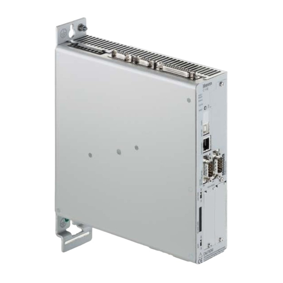
Page 71: Device View
Mechanical installation Device view Figure 9: item Servo Positioning Controller C 3-10: front view Page 71... -
Page 72: Figure 10: Item Servo Positioning Controller C 3-05: View From Above
[X11] OUT [X10] IN [X1] I/O [X9.] BR-CH BR-INT BR-EXT +24V GND24V Figure 10: item Servo Positioning Controller C 3-05: view from above [X6.] [X2B] ENCODER [X2A] RESOLVER Figure 11: item Servo Positioning Controller C 3-05: view from below Page 72... -
Page 73: Installation
Installation The item Servo Positioning Controller C 3-Series has fastening tabs at the top and bottom. These tabs are used to mount the servo positioning controller vertically to a control cabinet plate. The tabs are part of the heat sink profile. This is why the best possible heat transfer to the control cabinet plate must be ensured. -
Page 74: Electrical Installation
Electrical installation Electrical installation Connector configuration The item Servo Positioning Controller C 3-Series is connected to the power supply, motor, braking resistor, and holding brake as shown in Figure 13 C 3-Series 230VAC ... 480 VAC +/- Automatic circuit Power Supply [X9]... -
Page 75: Item C 3-Series - Complete System
The item Servo Positioning Controller C 3-Series must be connected to earth (ground) with its PE connector. As a first step, the item Servo Positioning Controller C 3-Series must be completely wired. It is only then that the operating voltages for the DC bus circuit and the electronic supply may be switched on. In the case of reverse connection of the operating voltage connectors, excessive operating voltage, or accidental interchanging of the operating voltage and motor connectors, the item Servo Positioning Controller C 3-Series will be damaged. -
Page 76: Figure 14: Complete Set-Up Of The Item C 3-Series With A Motor And Pc
Electrical installation Figure 14: Complete set-up of the item C 3-Series with a motor and PC Page 76... -
Page 77: Connector: Power Supply [X9]
Electrical installation Connector: power supply [X9] The item Servo Positioning Controller C 3-Series receives its 24 VDC power supply for the electronic control system via connector [X9]. The mains power supply is a three-phase system. As an alternative to AC power supply or for the purpose of DC bus circuit linking, a direct DC supply for the DC bus circuit is possible. -
Page 78: Pin Assignment [X9]
Electrical installation 8.3.3 Pin assignment [X9] Table 33: Pin assignment [X9] Pin no. Name Value Specification 230 ... 480 VAC [± 10%], Mains phase 1 50 ... 60 Hz Mains phase 2 Mains phase 3 < 700 VDC Pos. DC bus circuit voltage GND_ZK Neg. -
Page 79: Connection Notes [X9]
GND24V Figure 15: Power supply [X9] The item Servo Positioning Controller C 3-Series has an internal brake chopper and braking resistor. For more braking power, an external braking resistor can be connected to the [X9] pin-and-socket connector. Table 34: Pin-and-socket connector [X9]: external braking resistor Pin no. -
Page 80: Connector: Motor [X6]
Electrical installation Connector: motor [X6] 8.4.1 Configuration on the device [X6] PHOENIX Power-COMBICON PC 4/9-G-7.62 BK 8.4.2 Mating connector [X6] PHOENIX Power-COMBICON PC 4 HV/9-ST-7.62 BK 8.4.3 Pin assignment [X6] Table 35: Pin assignment [X6] Pin no. Name Value Specification 0 V brake... -
Page 81: Cable Type And Configuration [X6]
Electrical installation 8.4.4 Cable type and configuration [X6] The cable names that are stated refer to cables made by Lapp. They have proved to be reliable and are successfully used in many applications. However, it is also possible to use comparable cables from other manufacturers, for example Lütze or Helukabel. -
Page 82: Figure 17: Connecting A Holding Brake With A High Current Demand (> 2 A) To The Device
Please note the maximum output current that is provided by the item Servo Positioning Controller C 3-Series. It may be necessary to connect a relay between the device and the holding brake as shown... -
Page 83: Connector: I/O Communication [X1]
24 V inputs and outputs: These signals refer to the 24 V supply voltage of the item Servo Positioning Controller C 3-Series, which is supplied via [X9]. They are separated from the reference potential of the control module by way of optocouplers. -
Page 84: Figure 18: Basic Circuit Diagram Of Connector [X1]
Electrical installation Control system item C 3-Series AIN 0 #AIN 0 Pin Nr. AGND AIN 0 AIN 1 / AIN 2 #AIN AIN 1 AIN 2 AGND +VREF +VREF + 15 V AGND AMON 0 AGND AMON 1 AMON x... -
Page 85: Configuration On The Device [X1]
+10 V. These outputs can be led to the superordinate control system; the reference potential AGND must be carried along. If the control system is equipped with differential inputs, the "+" input of the control system is connected to the output of the item Servo Positioning Controller C 3-Series and the "-"... -
Page 86: Pin Assignment [X1]
Electrical installation 8.5.3 Pin assignment [X1] Table 36: Pin assignment: I/O communication [X1] Pin no. Name Value Specification AGND Shield for analogue signals, AGND AGND Reference potential for analogue signals AIN 0 = ± 10 V Setpoint input 0, differential, ≥... -
Page 87: Cable Type And Configuration [X1]
For optimal interference suppression of the analogue signals, the cores for the analogue signals must be shielded together and separate from other cores. This internal cable shield is connected to AGND (pin 1 or 14) on one side of the item C 3- Series. -
Page 88: Connector: Resolver [X2A]
Electrical installation Connector: resolver [X2A] 8.6.1 Configuration on the device [X2A] D-SUB connector, 9-pin type, female 8.6.2 Mating connector [X2A] D-SUB connector, 9-pin type, male Housing for a 9-pin D-SUB connector with locking screws of type 4/40 UNC ... -
Page 89: Cable Type And Configuration [X2A]
The outer shield is always connected to PE (connector housing) on the controller side. The three inner shields are connected to PIN 3 of [X2A] on one side of the item Servo Positioning Controller C 3-Series. Page 89... -
Page 90: Connector: Encoder [X2B]
Electrical installation Connector: encoder [X2B] 8.7.1 Configuration on the device [X2B] D-SUB connector, 15-pin type, female 8.7.2 Mating connector [X2B] D-SUB connector, 15-pin type, male Housing for a 15-pin D-SUB connector with locking screws of type 4/40 UNC ... -
Page 91: Pin Assignment [X2B]
Electrical installation 8.7.3 Pin assignment [X2B] Table 38: Pin assignment: analogue incremental encoder – option [X2B] Pin no. Name Value Specification + 3.3 V / Ri = 2 kΩ Motor temperature sensor , normally closed contact, PTC, KTY ... U_SENS+ 5 V ... -
Page 92: Table 39: Pin Assignment: Incremental Encoder With A Serial Interface (E.g. Endat, Hiperface) - Option [X2B]
Electrical installation Table 39: Pin assignment: incremental encoder with a serial interface (e.g. EnDat, HIPERFACE) – option [X2B] Pin no. Name Value Specification + 3.3 V / Ri = 2 kΩ Motor temperature sensor , normally closed contact, PTC, KTY ... U_SENS+ 5 V ... -
Page 93: Cable Type And Configuration [X2B]
Electrical installation Table 40: Pin assignment: digital incremental encoder – option [X2B] Pin no. Name Value Specification + 3.3 V / Ri = 2 kΩ Motor temperature sensor , normally closed contact, PTC, KTY ... U_SENS+ 5 V ... 12 V Sensor cables for the encoder supply ≈... -
Page 94: Connection Notes [X2B]
Electrical installation 8.7.5 Connection notes [X2B] D-SUB connector at Output of the analogue incremental encoder interface at the motor TEMP- TEMP+ U_SENS+ U_SENS- COS_Z1 #COS_Z1 SIN_Z1 #SIN_Z1 Male COS_Z0 #COS_Z0 SIN_Z0 #SIN_Z0 Connector Cable shield housing (optional) Connector housing Figure 20: Pin assignment: analogue incremental encoder –... -
Page 95: Figure 22: Pin Assignment: Digital Incremental Encoder - Option [X2B]
Electrical installation D-SUB connector Output of the digital incremental at X2B encoder at the motor TEMP- TEMP+ SENSE+ SENSE- HALL_U HALL_V HALL_W Male Connector Cable shield housing (optional) Connector housing Figure 22: Pin assignment: digital incremental encoder - option [X2B] Page 95... -
Page 96: Connector: Incremental Encoder Input [X10]
Electrical installation Connector: incremental encoder input [X10] 8.8.1 Configuration on the device [X10] D-SUB connector, 9-pin type, female 8.8.2 Mating connector [X10] D-SUB connector, 9-pin type, male Housing for a 9-pin D-SUB connector with locking screws of type 4/40 UNC ... -
Page 97: Cable Type And Configuration [X10]
Electrical installation 8.8.4 Cable type and configuration [X10] We recommend using encoder connecting cables in which the incremental encoder signals are twisted in pairs and the individual pairs are shielded. 8.8.5 Connection notes [X10] Input [X10] can be used to process incremental encoder signals and pulse direction signals like the ones generated by the control boards for stepper motors. -
Page 98: Connector: Incremental Encoder Output [X11]
Electrical installation Connector: incremental encoder output [X11] 8.9.1 Configuration on the device [X11] D-SUB connector, 9-pin type, female 8.9.2 Mating connector [X11] D-SUB connector, 9-pin type, male Housing for a 9-pin D-SUB connector with locking screws of type 4/40 UNC ... -
Page 99: Cable Type And Configuration [X11]
We recommend using encoder connecting cables in which the incremental encoder signals are twisted in pairs and the individual pairs are shielded. 8.9.5 Connection notes [X11] Incremental encoder input D-SUB connector (e.g. item Servo Positioning at X11 Controller C Series, X10) Incremental encoder output Male Cable shield... -
Page 100: Connector: Can Bus [X4]
Connector for the cable shield An external terminating resistor of 120 Ω is required on both ends of the bus. If the bus ends are not formed by item Servo Positioning Controller C 3-Series with integrated terminating resistors, we recommend using metal film resistors with a 1% tolerance of type 0207, e.g. -
Page 101: Cable Type And Configuration [X4]
Electrical installation 8.10.4 Cable type and configuration [X4] The cable names that are stated refer to cables made by Lapp. They have proved to be reliable and are successfully used in many applications. However, it is also possible to use comparable cables from other manufacturers, for example Lütze or Helukabel. -
Page 102: Figure 26: Integrated Can Terminating Resistor
Figure 25) to controller (see A terminating resistor of 120 Ω ± 5% must be present on both ends of the CAN bus cable. The item Servo Positioning Controller C 3-Series is equipped with an integrated terminating resistor that can be activated/deactivated via the DIP Figure 26 switch "CAN TERM"... -
Page 103: Connector: Rs232/Com [X5]
Electrical installation 8.11 Connector: RS232/COM [X5] 8.11.1 Configuration on the device [X5] D-SUB connector, 9-pin type, male 8.11.2 Mating connector [X5] D-SUB connector, 9-pin type, female Housing for a 9-pin D-SUB connector with locking screws of type 4/40 UNC ... -
Page 104: Cable Type And Configuration [X5]
Electrical installation 8.11.4 Cable type and configuration [X5] Interface cable for the serial interface (null modem), 3 cores 8.11.5 Connection notes [X5] D-SUB connector at X5 Female Female Connector housing Connector housing Figure 27: Pin assignment RS232 null modem cable [X5] Page 104... -
Page 105: Connector: Usb [X19]
Electrical installation 8.12 Connector: USB [X19] 8.12.1 Configuration on the device [X19] USB connector (female), type B 8.12.2 Mating connector [X19] USB connector (male), type B 8.12.3 USB [X19] Table 45: Pin assignment USB interface [X19] Pin no. Name Value Specification... -
Page 106: Sd/Mmc Card
Electrical installation 8.13 SD/MMC card 8.13.1 Supported card types SDHC 8.13.2 Supported functions Loading of a parameter set (DCO file) Saving of the current parameter set (DCO file) Loading of a firmware file 8.13.3 Supported file systems FAT12 ... -
Page 107: 8.13.5 Pin Assignment Sd/Mmc Card
Electrical installation 8.13.5 Pin assignment SD/MMC card Table 46: Pin assignment: SD card Pin no. Name SD mode SPI mode DATA3/CS Data line 3 (bit 3) Chip select CMD/DI Command/response Host to card commands and data Vss1 Supply voltage earth (ground) Supply voltage earth (ground) Supply voltage Supply voltage... -
Page 108: 8.13.6 Boot-Dip Switch
Electrical installation 8.13.6 BOOT-DIP switch During a restart/reset, the BOOT DIP switch is used to determine whether to perform a firmware download from the SD/MMC card or not. BOOT DIP switch in position "ON" firmware download requested BOOT DIP switch in position "OFF" firmware download not requested ... -
Page 109: Notes Concerning The Safe And Emc-Compliant Installation
In order to increase interference immunity and to decrease interference emissions, the item Servo Positioning Controller C 3- Series has integrated output chokes and line filters so that it can be used without additional shielding and filtering devices in most applications. -
Page 110: 8.14.4 Emc-Compliant Cabling
The following must be considered for the EMC-compliant set-up of the drive system (see also page 74 In order to keep the leakage currents and losses in the motor connecting cable as small as possible, the item Servo chapter 8.14.5 Operation... -
Page 111: 8.14.5 Operation With Long Motor Cables
Electrical installation DANGER! For safety reasons, all of the PE earth (ground) conductors must be connected prior to the initial operation of the system. The EN 61800-5-1 regulations concerning protective earthing (grounding) must be complied with during the installation! 8.14.5 Operation with long motor cables In applications involving long motor cables and/or in the case of unsuitable motor cables with a non-permissible high cable capacity, the filters may be thermally overloaded. -
Page 112: 8.14.6 Esd Protection
To prevent electrostatic discharge, protective caps are available from specialised suppliers (e.g. Spoerle). The item Servo Positioning Controller C 3-Series has been designed to provide high interference immunity. For this reason, some function blocks are electrically isolated. Inside the device, the signals are transmitted via optocouplers. -
Page 113: Additional Requirements To Be Fulfilled By The Servo Positioning Controllers For Ul Approval
Additional requirements to be fulfilled by the servo positioning controllers for UL approval Additional requirements to be fulfilled by the servo positioning controllers for UL approval This chapter provides further information concerning the UL approval of the C 3-05 and C 3-10 devices. Mains fuse In case of a required UL certification, the following data for the mains fuse must be complied with: Listed circuit breaker in accordance with UL 489, rated 480Y/277 VAC, 16 A, SCR 10 kA... -
Page 114: Start-Up
Start-up Start-up 10.1 General connection notes Since the laying of the connecting cables is essential in terms of EMC, compliance with the information given chapter 8.14.4 EMC-compliant cabling (page 110) in the previous must be absolutely ensured! DANGER! chapter 2 Safety notes for electrical drives and controllers (as of page Non-compliance with the instructions in may result in damage to property, personal injury, electric shock, or, in extreme cases, in death. -
Page 115: Connecting The Item Servo Positioning Controller C 3-Series To The Power Supply
Plug the plug A of the USB interface cable into the socket for the USB interface of the PC. Plug the plug A of the USB interface cable into the [X19] USB socket of the item Servo Positioning Controller C 3-Series. ... -
Page 116: Service Functions And Error Messages
11.1.1 Overview The item Servo Positioning Controller C 3-Series has an extensive sensor system that monitors the controller unit, power output stage, motor, and the communication with the outside world. Errors that occur will be stored in the internal error memory. -
Page 117: 11.1.3 Overcurrent And Short-Circuit Monitoring
11.1.7 I²t monitoring The item Servo Positioning Controller C 3-Series has an I²t monitoring system to limit the average power loss in the power output stage and in the motor. Since the power loss in the electronic power system and in the motor increases in a square manner with the current in the worst case, the squared current value is taken as the measure for the power loss. -
Page 118: 11.1.8 Power Monitoring Of The Brake Chopper
Servo positioning controllers, which are sent to item for service, will be equipped with a different firmware and different parameters for testing purposes. Before the end user uses the item Servo Positioning Controller C 3-Series once again, it must be parameterised. The item ®... -
Page 119: Operating Mode And Error Messages
A warning will be displayed at least twice on the seven-segment-display. The numbers are successively displayed. Option "STO" (Safe Torque-Off) active for the item servo positioning controller C Series. (seven-segment display = "H", blinking with a frequency of 2 Hz) -
Page 120: 11.2.2 Error Messages
11.2.2 Error messages If an error occurs, the item servo positioning controller C Series will display an error message cyclically by way of its seven- segment display. The error message is comprised of an "E" (for error), a main index (xx), and a subindex (y), for example E 0 1 0. - Page 121 Service functions and error messages Table 50: Error messages Error message Meaning of the error message Measures Main Sub index index Invalid error Information: Only for connected service module. An invalid (corrupted) entry in the error buffer has been marked by this error number.
- Page 122 Service functions and error messages Error message Meaning of the error message Measures Main Sub index index Undervoltage of the DC bus circuit Error priority set too high? Check the power supply. Check (measure) the DC bus circuit voltage. Check the response threshold of the DC bus circuit monitoring system.
- Page 123 Service functions and error messages Error message Meaning of the error message Measures Main Sub index index X10, X11 and RS232 supply voltage Check the pin assignment of the connected peripheral failure equipment. Check the connected peripheral equipment for short-circuits. Safety module internal voltage failure Safety module defective? Replace the safety module.
- Page 124 Service functions and error messages Error message Meaning of the error message Measures Main Sub index index Internal angle encoder error The internal monitoring system of the angle encoder at [X2B] has detected an error. Communication error? If necessary, contact the Technical Support. Encoder at [X2B] not supported Please contact the Technical Support.
- Page 125 Service functions and error messages Error message Meaning of the error message Measures Main Sub index index Homing: timeout The maximum time that has been parameterised for homing has been reached before the homing run could be completed. Check the parameterisation of the time. Homing: wrong/invalid limit switch The associated limit switch is not connected.
- Page 126 Service functions and error messages Error message Meaning of the error message Measures Main Sub index index CAN: Align the cycle time of the remote frames with the PLC or node Guarding failure of the PLC. Signals disturbed? CAN: Check the configuration. RPDO too short CAN: Check the command syntax of the control (record the data...
- Page 127 Service functions and error messages Error message Meaning of the error message Measures Main Sub index index Invalid number of pole pairs The calculated number of pole pairs is beyond the parameterisation range. Check the data sheet of the motor. If necessary, contact the Technical Support.
- Page 128 Service functions and error messages Error message Meaning of the error message Measures Main Sub index index PROFIBUS: Check the slave address. communication error Check the bus terminators. Check the cabling. PROFIBUS: Incorrect slave address. Please select another slave address. invalid slave address PROFIBUS: error in value range Mathematical error during the conversion of physical units.
- Page 129 Service functions and error messages Error message Meaning of the error message Measures Main Sub index index Error in data tables (CAM) Load the default parameter set and perform a start-up procedure. If necessary, reload the parameter set. If necessary, contact the Technical Support. Following error warning threshold Check the parameterisation of the following error.
- Page 130 Service functions and error messages Error message Meaning of the error message Measures Main Sub index index DC bus circuit discharge time exceeded Bridge for the internal brake resistor installed? Check the connection of the external braking resistor. If necessary, contact the Technical Support. No power supply for the controller No DC bus circuit voltage? enable signal...
- Page 131 Service functions and error messages Error message Meaning of the error message Measures Main Sub index index Positioning: no follow-up position: stop The positioning target cannot be reached with the current positioning options or boundary conditions. Positioning: reversal of rotation not Check the positioning parameters.
- Page 132 Service functions and error messages Error message Meaning of the error message Measures Main Sub index index No or unknown FSM module or faulty Cause: Internal voltage error of the safety module or of driver supply the fieldbus activation module. Action: Module presumably defective.
- Page 133 Service functions and error messages Error message Meaning of the error message Measures Main Sub index index Action: Identify interfering radiators in the environment of the servo drive. Replace module or basic device. Please contact the Technical Support. ...
- Page 134 Service functions and error messages Error message Meaning of the error message Measures Main Sub index index FSM: Rotational speed limits in basic Cause: Basic device reports error if the currently device overlap requested direction of movement is not possible because the safety module has blocked the setpoint value in this direction.
- Page 135 Service functions and error messages Error message Meaning of the error message Measures Main Sub index index Action: See USF0, error 53-0. USF3: Safety condition violated Cause: Violation of monitored speed limits of the SSF3 in operation / when USF3 / SSF3 requested. Action: See USF0, error 53-0.
- Page 136 Service functions and error messages Error message Meaning of the error message Measures Main Sub index index Action: Check when the violation of the safety condition occurs: During dynamic braking to zero. After the drive has reached zero speed. With a) Check of braking ramp – record ...
- Page 137 Service functions and error messages Error message Meaning of the error message Measures Main Sub index index Action: Check when the violation of the safety condition occurs: During dynamic braking to zero. After the drive has reached zero speed. With a) Check of braking ramp – record ...
- Page 138 Service functions and error messages Error message Meaning of the error message Measures Main Sub index index Action: Check whether the error can be acknowledged and whether it occurs again upon a new STO request – if yes: Basic device is presumably faulty.
- Page 139 Service functions and error messages Error message Meaning of the error message Measures Main Sub index index Action: Error may occur with SIN/COS and Hiperface encoders. Check the position encoder. Check the connection wiring (broken wire, short between two signals or signal / screening).
- Page 140 Service functions and error messages Error message Meaning of the error message Measures Main Sub index index Action: Check the position encoder at X2B. Check the connection wiring (broken wire, short between two signals or signal / screening). Check the supply voltage for the ENDAT ...
- Page 141 Service functions and error messages Error message Meaning of the error message Measures Main Sub index index Action: Check the connected position encoder: If further error messages occur in conjunction with the encoders, then eliminate their cause first. Check the motor and encoder cable / ...
- Page 142 Service functions and error messages Error message Meaning of the error message Measures Main Sub index index Error, cross-comparison of encoder Cause: Cross-comparison between µC1 and µC2 has analysis detected an angle difference or rotational speed difference or difference in capture times for the position encoders.
- Page 143 Service functions and error messages Error message Meaning of the error message Measures Main Sub index index Action: Check the connection wiring for the digital outputs DOUT40 ... DOUT42 (short circuit, cross circuit, etc.). Check the connection wiring for the brake ...
- Page 144 Service functions and error messages Error message Meaning of the error message Measures Main Sub index index Action: Check the external active and passive sensors – do they switch on two channels and simultaneously (within the parameterised discrepancy time). Two-handed control device: Check how the ...
- Page 145 Check whether the firmware versions of the safety module and basic device and the versions of the item Motion Soft® and SafetyTool are compatible. Packet counter error during transmission Communication module - basic device Cause: ...
- Page 146 Check whether the firmware versions of the safety module and basic device and the ® versions of the item Motion Soft SafetyTool are compatible. Error in cross-comparison for Cause: Timeout during cross-comparison (no data) or processors 1 - 2 cross-comparison faulty (data for µC1 and µC2...
- Page 147 Service functions and error messages Error message Meaning of the error message Measures Main Sub index index Action: This is an internal error in the module that should not occur during operation. Check the operating conditions (temperature, air humidity, condensation). Check the EMC wiring as specified and ...
- Page 148 - does it contain a valid parameter set? Read out and analyse the permanent event memory of the basic device via item Motion Soft® Eliminate error causes step by step. Install safety module with “delivery status”...
- Page 149 Service functions and error messages Error message Meaning of the error message Measures Main Sub index index Action: Check the firmware version of the basic device and the version of the safety module – update available? Safety module faulty; replace. ...
- Page 150 Service functions and error messages Error message Meaning of the error message Measures Main Sub index index DeviceNet: overflow of transmit buffer Reduce the number of message per time unit that are to be transmitted. DeviceNet: IO send error Please contact the Technical Support. DeviceNet: bus Off Check the DeviceNet wiring.
- Page 151 Service functions and error messages Error message Meaning of the error message Measures Main Sub index index IRQ: speed controller overflow IRQ: position controller overflow IRQ: interpolator overflow IRQ: Please contact the Technical Support. low-level overflow IRQ: MDC overflow Sequence control: general For information only, no measures required.
- Page 152 Service functions and error messages Error message Meaning of the error message Measures Main Sub index index IRQ 0 (current controller): trigger error CAN controller not available Device parameters checksum error DEBUG-Firmware loaded Internal initialisation error Please contact the Technical Support. Memory error Controller/power stage code read error Internal software initialization error...
-
Page 153: Technology Modules
The PROFIBUS-DP interface provides an additional fieldbus connection. All of the functions and parameters can be addressed directly, for example from a Simatic S7 control system. The interface is plugged into the technology slot TECH 2 of the item servo positioning controller C Series. -
Page 154: Figure 30: Profibus-Dp Interface: Front View
Technology modules Table 52: Technical data: PROFIBUS-DP interface: interfaces and communication Communication interface PROFIBUS module Controller PROFIBUS controller VPC3+, 12 Mbaud max. Protocol PROFIBUS-DP, 32-byte telegrams with operating-mode-depending configuration Interface Floating, D-SUB 9-pin, integrated bus terminating resistors (can be activated by DIP switches) Special functions Support of diagnosis data, RTS signal led out, fail-safe mode, sync/freeze... -
Page 155: Pin Assignment And Cable Specifications
Technology modules 12.1.3 Pin assignment and cable specifications 12.1.3.1 Pin assignment 9-pin DSUB connector, female Table 53: Pin assignment: PROFIBUS-DP interface Pin no. Name Values Specification Shield Cable shield + 5 V +5 V – output (floating) Not used Not used RxD / TxD-P Receive/transmit data B-line... -
Page 156: Termination And Bus Terminating Resistors
Technology modules 12.1.4 Termination and bus terminating resistors All of the bus segments of a PROFIBUS network must be equipped with bus terminating resistors to minimise line reflections and to adjust a defined rest potential on the line. The bus termination must be provided at the beginning and at the end of every bus segment. -
Page 157: Ethercat
EtherCAT 12.2.1 Product description The EtherCAT technology module enables the connection of the item servo positioning controller C Series to the EtherCAT fieldbus system. The communication via the EtherCAT interface (IEEE-802.3u) is realised with the aid of standard EtherCAT cabling. -
Page 158: Technical Data
Technology modules Figure 32: EtherCAT module: front view 12.2.3 Technical data Table 54: Technical data: EtherCAT module: ambient conditions, dimensions, and weight Range Values Storage temperature range - 25°C to + 75°C Operating temperature range 0°C to 50°C Atmospheric humidity 0 ... -
Page 159: Ethercat Interface
Technology modules Element Function LED 1 Run (green), link/activity EtherCAT port 1 (red), Two-colour-LED (green/red) EtherCAT active (yellow) LED 2 (red) Link/activity EtherCAT port 2 12.2.5 EtherCAT interface Table 56: Signal level and differential voltage Signal level 0 ... 2.5 VDC Differential voltage 1.9 ... -
Page 160: General Installation Notes For Technology Modules
Ensure that ESD protection measures are applied when handling technology modules. To insert a technology module into the item Servo Positioning Controller C 3-Series, please proceed as follows: Remove the front plate of the technology slot (TECH 1 or TECH 2) of the servo positioning controller with a suitable Phillips screwdriver.
Need help?
Do you have a question about the C 3-Series and is the answer not in the manual?
Questions and answers