Daikin Sky Air Alpha Series Installation Manual
Hide thumbs
Also See for Sky Air Alpha Series:
- Installer's reference manual (88 pages) ,
- Installation manual (20 pages) ,
- Installer's reference manual (36 pages)

Related Manuals for Daikin Sky Air Alpha Series


Summary of Contents for Daikin Sky Air Alpha Series
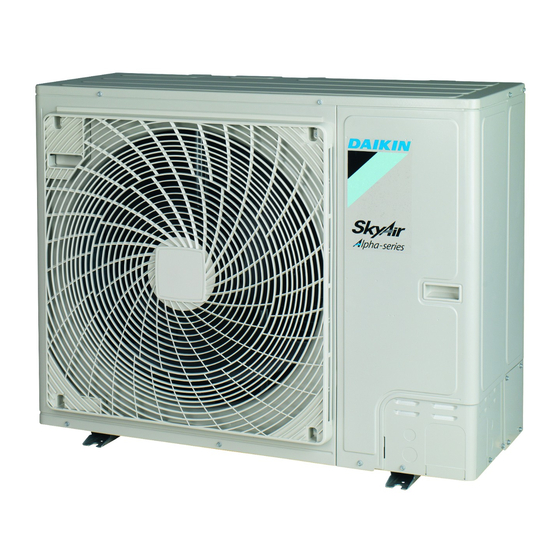
- Page 1 Installation manual Sky Air Alpha-series RZAG71N2V1B RZAG100N2V1B RZAG125N2V1B RZAG140N2V1B RZAG71N2Y1B RZAG100N2Y1B Installation manual RZAG125N2Y1B English Sky Air Alpha-series RZAG140N2Y1B...
- Page 2 (mm) — ≥100 A, B, C — ≥100 ≥100 ≥100 B, E — ≥100 ≥1000 ≤500 A, B, C, E — ≥150 ≥150 ≥150 ≥1000 ≤500 — ≥500 D, E — ≥500 ≥1000 ≤500 >H B, D ≥100 ≥500 ≤H ≥100 ≥500 B, D, E...
- Page 3 2P573424-5D...
- Page 4 2P573424-5D...
- Page 5 2P573424-6D...
- Page 6 2P573424-6D...
-
Page 7: Table Of Contents
Checking refrigerant piping: Setup......13 Daikin website (publicly accessible). 5.3.2 To check for leaks............13 ▪ The full set of latest technical data is available on the Daikin 5.3.3 To perform vacuum drying .......... 13 Business Portal (authentication required). Charging refrigerant ..............13 5.4.1... - Page 8 2 Specific installer safety instructions WARNING CAUTION If appliances contain R32 refrigerant, the floor area of the Install the refrigerant piping or components in a position room in which the appliances are installed, operated and where they are unlikely to be exposed to any substance stored MUST be larger than the minimum floor area which may corrode components containing refrigerant, defined in table below A (m...
- Page 9 2 Specific installer safety instructions WARNING CAUTION ▪ Only use R32 as refrigerant. Other substances may ▪ When connecting the power supply: connect the earth cause explosions and accidents. cable first, before making current-carrying connections. ▪ R32 contains fluorinated greenhouse gases. Its global warming potential (GWP) value is 675.
-
Page 10: About The Box
3 About the box About the box Outdoor unit 4× M12 3.1.1 To remove the accessories from the outdoor unit 1× 1× 2× 1× 1× 1× ENERG ENERG (mm) Make sure not to cover the drain holes of the bottom plate of the unit. -
Page 11: To Prevent The Outdoor Unit From Falling Over
5 Installation 3 Remove the burrs, and paint the edges and areas around the NOTICE edges using repair paint to prevent rusting. If the unit CANNOT be installed fully level, always make sure that the inclination is towards the backside of the unit. NOTICE This is required to guarantee proper drainage. - Page 12 5 Installation 4 Do the following: ▪ Insulate the liquid piping (a) and the gas piping (b). ▪ Wind heat insulation around the curves, and then cover it with vinyl tape (c). 2 Choose a piping route (a, b, c or d). ▪...
-
Page 13: Checking The Refrigerant Piping
5 Installation 5.3.3 To perform vacuum drying WARNING Provide adequate measures to prevent that the unit can be NOTICE used as a shelter by small animals. Small animals that make contact with electrical parts can cause malfunctions, ▪ Connect the vacuum pump to both the service port of smoke or fire. -
Page 14: About The Refrigerant
5 Installation Completely recharging refrigerant 5.4.2 About the refrigerant Before completely recharging refrigerant, make sure the following is This product contains fluorinated greenhouse gases. Do NOT vent done: gases into the atmosphere. 1 All refrigerant is recovered from the system. Refrigerant type: R32 2 The outdoor unit's external refrigerant piping is checked (leak Global warming potential (GWP) value: 675... -
Page 15: Charging Additional Refrigerant
5 Installation Triple Double twin G1 (m) Total length of <x> liquid piping x=Ø9.5 mm (standard) x=Ø12.7 mm (size‑up) G2 (m) Total length of Ø6.4 mm liquid piping 2 Determine R1 and R2. Then G1>40 m Use the table below to determine R1 (length=G1−40 m) and R2 (length=G2). -
Page 16: Completely Recharging Refrigerant
5 Installation Operate the switches and push buttons with an insulated stick (such To charge additional refrigerant as a closed ball-point pen) to avoid touching of live parts. WARNING ▪ Only use R32 as refrigerant. Other substances may cause explosions and accidents. ▪... -
Page 17: To Fix The Fluorinated Greenhouse Gases Label
5 Installation 4 Charge the complete refrigerant amount. Connecting the electrical wiring 5 Deactivate the vacuum mode (see "To activate/deactivate the setting" [ 4 16]). DANGER: RISK OF ELECTROCUTION vacuum mode field 6 Open the gas stop valve. WARNING 5.4.7 To fix the fluorinated greenhouse gases ALWAYS use multicore cable for power supply cables. - Page 18 5 Installation Cable tie 1~ 50 Hz 3N~ 50 Hz 3 Fix the cables (power supply and interconnection cable) with a 220-240 V 380-415 V L1 L2 L3 cable tie to the stop valve attachment plate and route the wiring according to the illustration above.
-
Page 19: Finishing The Outdoor Unit Installation
1 Perform introductory steps. the customer. This data can be found in the installer reference guide Action or via the Daikin website. Open the liquid stop valve and gas stop valve by NOTICE removing the cap and turning counterclockwise with a ALWAYS operate the unit with thermistors and/or pressure hex wrench until it stops. -
Page 20: Error Codes When Performing A Test Run
7 Disposal Action Result Error codes when performing a Press at least 4 seconds. The Service Settings menu test run is displayed. If the installation of the outdoor unit has NOT been done correctly, the following error codes may be displayed on the user interface: Select Test Operation. -
Page 21: Technical Data
8 Technical data Technical data A subset of the latest technical data is available on the regional Daikin website (publicly accessible). The full set of latest technical data is available on the Daikin Business Portal (authentication required). Service space: Outdoor unit... -
Page 22: Piping Diagram: Outdoor Unit
8 Technical data Piping diagram: Outdoor unit Electronic expansion valve 4‑way valve High pressure switch Low pressure switch Compressor accumulator Heat exchanger Compressor Distributor Accumulator Service port (with 5/16" flare) Stop valve Field piping (liquid: Ø9.5 flare connection) Filter Field piping (gas: Ø15.9 flare connection) PCB cooling Heating Cooling... - Page 23 8 Technical data Bottom plate heater (option) Fuse HAP (A1P) Light-emitting diode (service monitor is green) K1M, K3M (A1P) (Y1 Magnetic contactor only) K1R (A1P) Magnetic relay (Y1S) K4R (A1P) Magnetic relay (E1H) K10R, K13R~K15R Magnetic relay (A1P) K11M (A1P) (V1 Magnetic contactor only) L1R (Y1 only)
- Page 24 4P695306-1 0000000R 4P695306-1 2022.05 Verantwortung für Energie und Umwelt...
Need help?
Do you have a question about the Sky Air Alpha Series and is the answer not in the manual?
Questions and answers