CYBEX V Series Assembly Instructions Manual
Hide thumbs
Also See for V Series:
- Assembly instructions manual (31 pages) ,
- Owner's manual (23 pages) ,
- Assembly instructions manual (23 pages)
Table of Contents
Advertisement
Quick Links
Advertisement
Table of Contents

Related Manuals for CYBEX V Series


Summary of Contents for CYBEX V Series
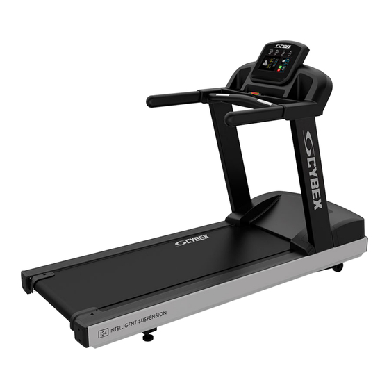
- Page 1 Cybex - V Series Treadmill Assembly Instructions Part Number 1018092-0001 AA...
- Page 3 United Kingdom All Other EMEA Countries and Distributor Business EMEA* North America Life Fitness UK LTD Bijdorpplein 25-31 2992 LB Barendrecht Cybex International Inc. Queen Adelaide THE NETHERLANDS Ely, Cambs, CB7 4UB 10601 W Belmont Ave Telephone: (+31) 180 646 644 Telephone: General Office (+44) 1353.666017...
- Page 4 User and Service Documents Link https://lifefitness9512.zendesk.com/hc/en-us https://lfworld.lifefitness.com Additional information is available online using the links above. أ علاه إل ر إبط باستخدإم إ لإ ن تر نت على إضافية معلومات تتوفر 点击上面的链接可在线获取更多信息。 Flere oplysninger er tilgængelige online gennem linket ovenfor. Bijkomende informatie is online beschikbaar via bovenstaande link.
-
Page 5: Table Of Contents
Cybex logo are registered trademarks of Cybex International, Inc. DISCLAIMER: Cybex International, Inc. makes no representations or warranties regarding the contents of this manual. We reserve the right to revise this document at any time or to make changes to the product described within it without notice or obligation to notify any person of such revisions or changes. -
Page 6: Getting Started
Getting Started Safety Instructions Read all instructions before use. CAUTION: Any changes or modifications to this equipment could void the product warranty. CAUTION: Risk of injury to persons – to avoid injury, use extreme caution when stepping onto or off of a moving belt. Read assembly instruction manual before using. - Page 7 • Do not use these products in bare feet. Always wear shoes. Wear shoes with rubber or high-traction soles. Do not use shoes with heels, leather soles, cleats or spikes. Make sure no stones are embedded in the soles. • Keep all loose clothing, shoelaces, and towels away from moving parts.
-
Page 8: Set-Up
Set-Up Read the entire manual before setting up the treadmill. Place the treadmill where it will be used before beginning the setup procedure. Electrical Power Requirements The treadmill requires a dedicated* line with isolated neutral according to the electrical configurations listed in the chart below. Supply Voltage (VAC) Frequency (Hz) Rated Current (Amps) - Page 9 How to Position and Stabilize the Treadmill Follow all safety instructions. Move the treadmill to the location in which it will be used. NOTE: See How to Adjust and Tension the Striding Belt to center the striding belt. Safety Clearances The following information is supplied as regional reference data regarding safety clearances around the exterior of the treadmill.
- Page 10 Power Switch Located on the front panel at the base of the treadmill, the ON/OFF switch has two positions: "I" (one) for ON and "0" (zero) for OFF. Power Cord Routing WARNING: Make sure the power cord is unplugged before attempting to route it around or through the treadmill. Connect the power cord to the power receptacle in the front of the treadmill.
-
Page 11: Product Overview
Product Overview Product Features Item Description Console Cup Holders Emergency Stop Lanyard Contact Heart Rate Sensors Handrails Striding Belt Mounting and Dismounting the Treadmill Use the handrails to enhance stability when mounting or dismounting a treadmill. Never mount or dismount the treadmill while the running belt is moving. -
Page 12: Assembly
Assembly Component and Hardware List Components Item Description Left Upright Right Upright Ergo™ Front Crossbar Upper Dashboard Tray Lower Dashboard Tray Console End Cap Front End Cap Rear Bridge Ergo™ Bar Backing Plate Cable Tie Hardware Item Description Bolt, 3/8 x 5” Hex Head Washer, 3/8”... -
Page 13: Tools Required
Tools Required • Phillips screwdriver • 9/16" Wrench (2) • 9/16" Socket 3/8" Drive • 13 mm Socket • 13 mm Wrench • 3" Extension 3/8" Drive • 3/8” Drive ratchet Remove Motor Cover 1. Remove screws securing motor cover to base assembly using a Phillips screwdriver. Item Description Motor Cover... -
Page 14: Install Uprights
Install Uprights 1. Place uprights on base assembly. 2. Install one bolt, washer, and lock nut to left and right upright and base assembly using a 9/16" socket and wrench. Item Description Left Upright Right Upright Bolt, 3/8 x 5” Hex Head Washer, 3/8”... -
Page 15: Install Front Crossbar
Install Front Crossbar 1. Route cable from front crossbar into left upright. Item Description Ergo™ Front Crossbar 2. Install bolts, washers, and lock nuts securing front crossbar to uprights using a 13mm socket and wrench. Item Description Lock Nut, M8 Washer, M8 Bolt, M8 x 20mm Hex Head Page 13 of 28... -
Page 16: Install Bridge
Install Bridge 1. Install a bolt, washers, and lock nut to each upright using a 13mm socket and wrench. Item Description Upright Lock Nut, M8 Washer, M8 Bolt, M8 x 20mm Hex Head NOTE: Leave a spacing of 5-12mm between washer and upright. 2. -
Page 17: Tighten Upper Hardware
3. Install bolts, washers, and lock nuts securing the bridge to uprights using a 13mm socket and wrench. Item Description Bridge Upright Lock Nut, M8 Washer, M8 Bolt, M8 x 20mm Hex Head Tighten Upper Hardware Tighten hardware 100%. Item Description Bolt, M8 x 20mm Hex Head Tighten Lower Hardware... -
Page 18: Install Console Cables And Grommets
Install Console Cables and Grommets NOTE: TV cables (Coax and power) are included in every treadmill with or without TV option. They must be routed up through left upright and stored in dashboard. 1. Route TV cables (Coax and power) up through left upright and into dashboard area. Item Description Coax Cable... -
Page 19: Install Upper Dashboard Tray
4. Secure cables from front crossbar and left upright to the bridge using cable ties. Install Upper Dashboard Tray 1. Install screws securing bar backing plate to front crossbar using a Phillips screwdriver. Item Description Ergo™ Bar Backing Plate Screw, #10 x 0.5” Phillips Head (black) 2. -
Page 20: Console Connections
Console Connections Item Description Qty. Display Connection Install Lower Dashboard Tray Install screws securing lower dashboard tray to upper dashboard tray using a Phillips screwdriver. Item Description Lower Dashboard Tray Screw, M4.2 x 19mm Phillips Head Screw, #10 x 0.5” Phillips Head (silver) Install Rear End Caps Install screws securing rear end caps to base assembly using a Phillips screwdriver. -
Page 21: Install Motor Cover
Install Motor Cover Install screws securing motor cover to base assembly using a Phillips screwdriver. Item Description Motor Cover Screw, M4.2 x 19mm Phillips Head Install Front End Caps Install screws securing front end caps to base assembly using a Phillips screwdriver. Item Description Front End Cap... - Page 22 2. Route power cord on left or right side of treadmill depending on installation / site needs. CAUTION: Make sure that there is 6.5 ft. (2 m) of clearance behind the treadmill. Contact Life Fitness Customer Support Services for an optional longer power cord if necessary. CAUTION: Insure that power cord does not contact striding belt or get pinched between frame, lift frame, or wheel.
-
Page 23: Service And Technical Data
Service and Technical Data Preventive Maintenance Schedule Item Weekly Monthly Biannually Console Overlays Clean Inspect Bottle Holders / Accessory Trays Clean Inspect Console Mounting Bolts Inspect Hardware Inspect Frame Clean Inspect Plastic Covers Clean Inspect Lifepulse Sensors Clean / Inspect Striding Belt Centered Inspect Emergency Stop Magnet... -
Page 24: Approved And Compatible Cleaners
Approved and Compatible Cleaners Two preferred cleaners have been approved by reliability experts: PureGreen 24 and Gym Wipes. Both cleaners will safely and effectively remove dirt, grime and sweat from equipment. PureGreen 24 and the Antibacterial Force formula of Gym Wipes are both disinfectants that are effective against MRSA and H1N1. -
Page 25: How To Obtain Product Service
Probable Cause Corrective Action Power source is insufficient. Plug treadmill into an appropriate circuit. Refer to Grounding Instructions. NOTE: In North America use a dedicated 20 amp circuit. Rubbing sound comes from underneath machine. Probable Cause Corrective Action Foreign objects may be stuck underneath the machine. Power down the unit and disconnect AC power. -
Page 26: How To Adjust And Tension The Striding Belt
NOTE: Do not exceed one full turn of the adjusting screws in either direction. If after one full turn the belt does not track properly, contact Cybex Customer Support. Do not overtighten the tensioning bolts while making belt adjustments. Overtightening of bolts may over stretch and damage the striding belt or roller. - Page 27 4. Repeat STEPS 2 and 3 until the belt no longer slips. Do not exceed one full turn (four quarter turns) per side when adjusting the belt tensioning bolts. 5. Press GO, operate the treadmill at 2.0 MPH (3.2 KPH) and check to insure proper tracking (see Tracking (Centering) A Striding Belt). If the striding belt drifts to the left or right see Centering an Existing or New Striding Belt .
-
Page 28: Specifications
Specifications Specifications Designed Use Heavy / Commercial, EN ISO 20957 Class S Maximum User Weight 400 lbs. / 181 kg Speed Range 0.5 - 12.0 MPH (0.8 - 19.3 KPH) in 0.1 increments Incline Range 0% - 15% Drive Train AC motor with variable speed controller Motor Type AC Induction... - Page 30 10601 W Belmont Ave, Franklin Park, IL 60131 • 800-351-3737 • 847-288-3700 • www.cybexintl.com...
Need help?
Do you have a question about the V Series and is the answer not in the manual?
Questions and answers