Table of Contents
Advertisement
Quick Links
TABLE OF CONTENTS
1 Specifications ----------------------------------------------------- 2
2 Location of Controls and Components ------------------- 3
3 Troubleshooting Guide ----------------------------------------- 5
4 Disassembly and Assembly Instructions ---------------- 6
4.1. Main body and the dust box separation-------------- 6
4.2. Motor removal ---------------------------------------------- 6
4.3. Air outlet cover unit removal ---------------------------- 8
4.4. Main switch (with fuse) removal ----------------------- 8
4.5. Fuse replacement ----------------------------------------- 9
4.6. Indicator pipe unit removal ------------------------------ 9
4.7. Cloth bag unit removal ----------------------------------- 9
5 Wiring Connection Diagram ---------------------------------10
6 Schematic Diagram ---------------------------------------------10
7 Exploded View and Replacement Parts List -----------12
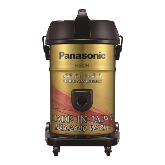
Model No.
Product Color : Gold
Destination
PAGE
7.1. EXPLODED VIEW (ATTACHMENTS) -------------- 12
7.2. PARTS LIST (ATTACHMENTS) ---------------------- 12
7.3. EXPLODED VIEW (BODY UNIT)-------------------- 13
7.4. PARTS LIST (BODY UNIT)---------------------------- 14
7.5. PACKING INSTRUCTIONS --------------------------- 15
7.6. PACKING LIST ------------------------------------------- 16
© Panasonic Corporation 2016 Unauthorized copy-
ing and distribution is a violation of law.
Order Number VCB01605001CE
Vacuum Cleaner
MC-YL799-N147
MC-YL799-N149
MC-YL799-N747
: 1.UAE ------------------------YL799-N147
2.Oman Kuwait ------------YL799-N149
3.Saudi Arabia Kuwait ---YL799-N747
PAGE
Advertisement
Table of Contents

Related Manuals for Panasonic MC-YL799-N147


Summary of Contents for Panasonic MC-YL799-N147
-
Page 1: Table Of Contents
4.6. Indicator pipe unit removal ------------------------------ 9 4.7. Cloth bag unit removal ----------------------------------- 9 5 Wiring Connection Diagram ---------------------------------10 6 Schematic Diagram ---------------------------------------------10 7 Exploded View and Replacement Parts List -----------12 © Panasonic Corporation 2016 Unauthorized copy- ing and distribution is a violation of law. -
Page 2: Specifications
1 Specifications Model No. MC-YL799 Motor power 2400W Dust capacity 21.0L Cord Length 8.0m Weight (With Attachments) 7.8kg METAL 2 Extension Wand Blower Operation Floor Nozzle 2-Step Attachments Crevice Tool / Upholstery Nozzle Specifications are subject to change without notice for further improvement. -
Page 3: Location Of Controls And Components
2 Location of Controls and Components... -
Page 5: Troubleshooting Guide
3 Troubleshooting Guide CONDITION CHECKPOINT METHOD OF INSPECTION CAUSE / REMEDY Fan motor unit fails to rotate when Meltdown of fuse unit • Check fuse continuity. Replace the main switch unit (with it is switched on (Visual and conduction check) fuse). -
Page 6: Disassembly And Assembly Instructions
4 Disassembly and Assembly Instructions Caution: 1. When disassembling, check the component fitting state and wirings. After repairing, always restore them to the original state. 2. Carefully handle the removed components, packing, etc. If they are damaged, then replace them with new ones. 3. - Page 7 3. Take the cord reel partition unit out from the body cover 5. Remove the lead wires by shifting the noise suppressor unit. unit. * Take care not to damage the noise suppressor when shifting the noise suppressor unit. <Assembly precaution> When mounting, align form of the motor support rub- ber (rear) unit with form of the body cover connection 6.
-
Page 8: Air Outlet Cover Unit Removal
4.4. Main switch unit (with fuse) 7. Remove the lead wires. * There is a tape (glass tape) wrapped on the faston removal terminals, and when removing the faston terminals, press on to the protrusion on the faston terminal 1. Remove the 2 screws mounting the handle. (arrow) as shown in fig. -
Page 9: Fuse Replacement
4.5. Fuse replacement * Fuse is supplied by the main switch unit (with fuse) 4.6. Indicator pipe unit removal 1. Remove the indicator pipe unit from the body upper. 4.7. Cloth bag unit removal 1. Remove the cloth bag unit from the expander. -
Page 10: Wiring Connection Diagram
5 Wiring Connection Diagram 6 Schematic Diagram... - Page 11 7 Pictorial Diagram NOTE: After servicing any electrical component or electrical enclosure, the unit should be reassembled and checked for dielectric breakdown or current leakage. Use Glass Tape (Refer to "Replacement Parts List") whenever original tape is removed...
-
Page 12: Exploded View And Replacement Parts List
8 Exploded View and Replacement Parts List 8.1. EXPLODED VIEW (ATTACHMENTS) 8.2. PARTS LIST (ATTACHMENTS) Safety Ref.No Service Parts No. Part Name & Description Q'TY Remarks AMV84P7X000J HOSE UNIT (HOSE)WITH PROJECTION AMC24P-0R0V HOSE SUPPORTER (PROJECTION) AMC98P4Y000J CURVED PIPE UNIT (CURVED WAND) WITH SUCTION REGULATOR AMV09PLV0K0J JOINT PIPE UNIT (HOSE CONNECTION WAND) -
Page 13: Exploded View (Body Unit)
8.3. EXPLODED VIEW (BODY UNIT) -
Page 14: Parts List (Body Unit)
EXHAUST PACKING UNIT AMV98ELD000J MAIN SWITCH UNIT AMV96LLD0K0J BLOWER OUTLET UNIT WITH COVER SPRING XTT4+20BFJ TRUSS SCREW AMV91NLD0K5J CORD REEL PARTITION UNIT MC-YL799-N147/MC-YL799-N747 AMV91NLD0KQJ CORD REEL PARTITION UNIT MC-YL799-N149 ONLY AMV46NLD0Y0J CORD REWIND BUTTON AMV71NBW000J SPRING BRAKE BUTTON AMC0NA-ZK0 GLASS TAPE... -
Page 15: Packing Instructions
8.5. PACKING INSTRUCTIONS... -
Page 16: Packing List
8.6. PACKING LIST Safety Ref.No Service Parts No. Part Name & Description Q'TY Remarks AMV61ZLV0N0J INDIVIDUAL CARTON AMV63ZLV000J BOTTOM PLATE AMC56Z-QN0 CUSHION BOTTOM AMV70ZLV000J CUSHION B AMV69ZLV000J CUSHION A AMV78ZLV000J SUPPORTER AMV72ZLV000J CUSHION PLATE A AMV01ZLV000J INSTRUCTION BOOK AMV21ZLV000J NOTE LABEL AMV10Z99000J BODY BAG...
Need help?
Do you have a question about the MC-YL799-N147 and is the answer not in the manual?
Questions and answers