Table of Contents
Advertisement
Quick Links
Advertisement
Table of Contents

Subscribe to Our Youtube Channel
Related Manuals for Ironwood COMPACT Series


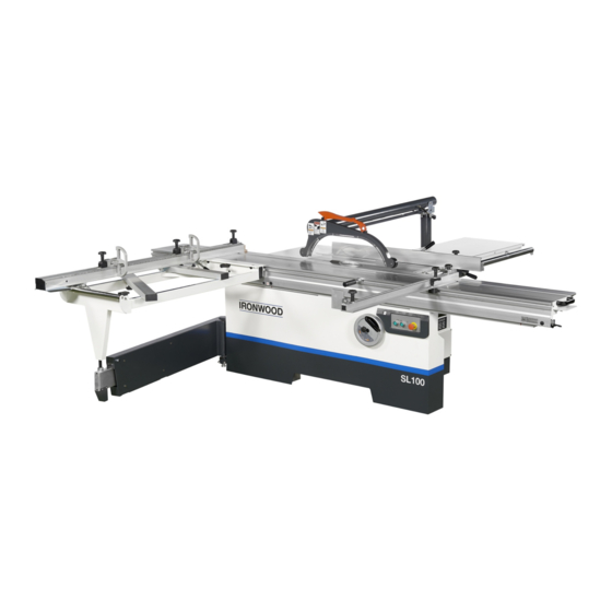
Summary of Contents for Ironwood COMPACT Series
- Page 1 SLIDING TABLE SAW COMPACT SERIES ORIGINAL OPERATING MANUAL...
- Page 3 Thank you very much for your purchasing our SLIDING TABLE SAW. For personal safety and excellent performance of the machine, please first carefully read the Operating Manual and other attachments to be familiar with the machine’s functions, safe instructions and notes. Noise range The figures quoted are emission levels and are not necessarily safe working levels.
-
Page 4: Table Of Contents
CATALOG SAFE INSTRUCTIONS EXPLANATION OF WARNING SIGN 1.BRIEF INTRODUCTION TO MACHINE 1-1 SPECIFICATION 1-2 MACHINE DIMENSION 1-3 FEATURES 1-4 INDICATION 1-5 RIVING KNIFE SPECIFICATION 2.SPARE PARTS ASSEMBLY UNIT 2-1 TRANSPORT 2-2 SLIDING TABLE UNIT 2-3 CROSSCUT TABLE UNIT 2-4 CROSSCUT FENCE UNIT 2-5 RIP FENCE UNIT 2-6 EXTENSION TABLE 2-7 DUST GUARD UNIT... - Page 5 6-5 FENCE UNIT 6-24 RIP FENCE CROSSCUT FENCE COMPACT16 CROSSCUT FENCE 6-26 CROSSCUT FENCE COMPACT19 26 32 CROSSCUT FENCE 6-27 6-29 MITER FENCE COMPACT19 26 32 MITER FENCE 6-6 SAFETY GUARD UNIT 6-30 SIMPLE TYPE SAW GUARD DUST-COLLECTING FASTENING RACK 6-31...
-
Page 6: Safe Instructions
1. If you are not fully familiar with the machine’s operation, you must be instructed by your supervisor or qualified person. 2. If the running direction of the saw is wrong, it will cause danger. 3. The anti-skid floor cushion is put at the operator ’s standing area and the machine’s working area. -
Page 7: Explanation Of Warning Sign
To secure safety Please make sure to carefully read the safe instructions to be familiar with the machine’s functions, safe information and notes before you start, run & start the machine. Please carefully read the trouble-shooting guide to be familiar with the machine’s functions, safe information and notes before you repair or check the breakdown. -
Page 9: Brief Introduction To Machine
1 . BRIEF INTRODUCTION TO MACHINE SPECIFICATION L S1 0 0 ITEM M O D EL R e c tifie d c a s t iro n fix e d ta b le d im e n s io n 5 7 0 x 8 8 0 Slid in g ta b le d im e n s io n 3 5 0 x 1 6 0 0... -
Page 10: Features
FEATURES : Dust guard Not only reduce dust produced by chips while cutting, but also warning the operator where the saw-blade position. : Main table Main working table. : Rip fence Reference positioning while ripping. : Sliding table Table for main feeding while cutting. : Controlling panel Control bottoms for start and stop. -
Page 11: Indication
INDICATION Fig.1 Fig.2 Fig.3 Note Fig. 1:the main saw's size and running direction. Fig. 2:the main saw's size and running direction. -
Page 12: Riving Knife Specification
RIVING KNIFE SPECIFICATION A : Available Main Saw diameter range. B : Riving knife depth. C : Simple riving knife. D : Luxurious riving WARNING Prior to setting the riving knife, check whether it matches the saw blade diameter and body thickness. Always switch off the main switch prior to setting the riving knife preventing cause danger. - Page 13 MACHINE NOISE DECLARED NOISE EMISSION VALUES in accordance with ISO 7960. Idling Operating Declared A-weighted Sound Power Level, Lward, in dB re 1 pW. Declared A-Weighted Emission Sound Pressure Level , lpAd , in dB re 20 μPa , at the operator’s position.
- Page 14 From the above measured results, this sliding table sawing machine present a little hearing or noise hazard to operator, the operator is required to wear ear caps whenever possible during operation and conform to the local safety regulations of labors. Noise level From the above measured results, this auto planer machine present no sever hearing or noise hazard to operator, However, the operator is recommended to wear ear caps...
-
Page 15: Spare Parts Assembly Unit
2 .SPARE PARTS ASSEMBLY UNIT TRANSPORT TRANSPORT WOODEN CRATE WARNING To transport the machine, please request the person who has licenses of gantry, crane, lift truck, etc, to operate. The weight of machine is listed in the chapter 2-1 and 2-2. After confirming, please proceed as per the weight. To suspend and move the machine, please follow Notes of Chapter 2-1 and 2-2 to operate. - Page 16 TRANSPORT MACHINE The machine's net weight is about : Body (Cutting width 1m):67 0kgs Body (Cutting width 1.3m):71 0kgs Body (Cutting width 1.5m):750kgs Please refer to Chapter 1-2 for detailed data. 1 . USE LIFT TRUCK TO TRANSPORT MACHINE WARNING ●The lift truck must be able to bear to least 5tons.
-
Page 17: Sliding Table Unit
SLIDING TABLE UNIT ASSEMBLE ★Prior to setting sliding table , release the trimming planks (Fig.2-2-1). Ensure the trimming planks releasing before 1 working operation or the machine damaged. Put the sliding table on the contact surface Clean the contact surface of the and tightly against the adjusting screw. - Page 18 ADJUST Adjust the adjusting screws at two sides Loosen 3 fixing screws. of the machine to make the sliding table parallel to the saw blade and keep the gap as shown in the left drawing with the working table. After assembling, tighten the fixing screws.
-
Page 19: Crosscut Table Unit
CROSSCUT TABLE UNIT ASSEMBLE Put one end of the crosscut table into Lock part A to fixcd the sliding table. the projected round rod of the expansion pipe ( apply the lubricating oil to the balls to prevent friction from Tighten the handle to fasten the Put two C-shaped aluminum pipes into the crosscut table. -
Page 20: Crosscut Fence Unit
CUOSSCUT FENCE UNIT ASSEMBLE Put the crosscut fence into the Press down the handle to fix the crosscut fence. positioning point of the crosscut Note : If the crosscut fence is moved, table. please first adjust the perpendicularity of fence and ADJUST saw blade before use. -
Page 21: Rip Fence Unit
RIP FENCE UNIT ASSEMBLE Use the gage to measure the parallelism of Lock the screw on the round rod the rip fence and the main saw blade. into the rihgt side of the working Measuring way : The rip fence is fixed and table, put into the rip fence base, the sliding table is pushed to the left. - Page 22 ● Tighten the rip scale, adjust the limit screw on the stop block. The safe gap between the fence and the saw blade is suggested at 15mm. ● The screw at the left side of above drawing is the limit for cutting 90 degree.
-
Page 23: Extension Table
EXTENSION TABLE ASSEMBLE MAIN TABLE EXTENSION Adjust 2 adjusting bolts of the Loosen about 3~5mm of 3 metal extension metal sheet to make the sheet fixing screws at the left side metal sheet and the main working of the machine, put extensnion table become a plane. - Page 24 ASSEMBLE WIDTH EXTENSION TABLE Lock the support into the back of Loosen 3~5mm of 4 metal sheet the machine. fixing screws at the left side of the Note : The opening of the support machine, put width extension must be outwards as shown table on the fixing screws, slightly in above drawing.
-
Page 25: Dust Guard Unit
DUST GUARD UNIT SIMPLE TYPE SAW GUARD Install the dust collection fixing Install the dust collecting hood on the ribbing knife, connect dust collection rack and the dust collection pipe hose, use clamp to fix the hose as onto the left side of the machine shown in above drawing. - Page 26 LUX SAW GUARD Install the dust collection fixing rack Parallelize the safety guard and onto the left side of the machine as the sliding table. then lock withe shown in above drawing. nuts. WARNING Before you install the safety guard, please lower the saw under the table.
- Page 27 ASSEMBLE It needs 2 people to install the safety guard . Fastening rack Fastening base Dust colletor fixed base and dust collector frame screw with nexagon screw and fixed as figA. After fixed check the nuts and make sure it's being completely locked. Dust collector Fastening rack Insert the dust collector into the...
- Page 28 Fixing ring Base ring Prop up the dust collector, tighten up part Fixing ring and part Base ring and then lock with nuts. Take out the nuts on the guard. Staff A lowers the dust collector down; staff B inserts the dust collector into the hole on the guard and lock with nuts.
- Page 29 Check the grooving Fig. A in the guard if parallel to the saw. (If not parallel please refer to Fig. 10 and 11, P.2-16) Make sure the guard parallel to the saw. Insert the indexing plungers to part A and lock the fixing ring with nuts. Install completed.
- Page 30 PUSHING STICK INSTALLING WARNING Before the machine is used to cut workpiece, Please make sure the dust collector work normally. Note1 : The required air speed at the end of flexible tube is 30~34m/sec. The required air volume of the machine is 1220~1390 m³/hr. (43,000~49,000 cuft/hr) Adjust dust collector to proper position and vertical to sliding table.Tighten hexagon screw on arrow sign A.
- Page 31 Make the guard to a proper position then adjust and fasten J1. (J1 is the max. height position; J2 is the max. low position. ) 2 position holes on the dust collector (as shown on ). (A) positioning hole is being used when the guard works. (B) positioning hole is being used when the guard stops.
-
Page 32: Miter Fence Unit
MITER FENCE UNIT ASSEMBLE Lock the fixing block on the sliding Put the slide block on the bevel table. cutting fence into the round rod of the sliding table. ● Tighten knob A to fasten the center point of bevel cutting fence. -
Page 33: Riving Knife Unit
RIVING KNIFE UNIT ADJUST ● Loosen the fixing screw on the Measure the relative size of the riving knife base. riving knife and saw blade. ● Adjust the 3 adjusting screws at WARNING the two sides of the fixing screws as After adjustment of the riving knife the projected place shown in the above drawing. -
Page 34: Main Saw Unit
MAIN SAW UNIT 2-10 CHANGE MAIN SAW BLADE DANGER ● Before changing saw blade, please confirm if power is closed. ● At changing saw blade, please put on the protective film to avoid any damage during changing. Push the sliding table towards the Open the saw blade guard. - Page 35 ADJUSTMENT FOR MAIN SAW HEIGHT AND TILTING. Hand wheel operation A. Hand wheel for main saw blade height adjustment. (As displaying in the diagram, the arrow direction is downward, on the contrary, upward.) B.Hand wheel for main saw blade tilting adjustment.
-
Page 36: Scoring Saw Unit
SCORING SAW UNIT 2-11 OPERATE A : Forward/backward adjusting knob. B : Lifting displacement knob. C : Lifting fixing knob. CHANGE DANGER ● Before changing the saw, please make sure if the power is closed to void danger. ● Before changing the saw please install the protective film to protect the saw and avoid danger while change Push the sliding table to the ottom,... -
Page 37: Protect Switch On The End Of Sliding Table
2-12 PROTECT SWITCH ON THE END OF SLIDING TABLE A: Should you accidently press the ON button when changing saw blade, this protect switch is able to keeps the saw blade standstill so that the operator won’t get hurt. Fig. 1 is the default installation Default Installation Fig. -
Page 38: Operating Unit
3 . OPERATING UNIT POWER CONNECTION DANGER ● Power connection must be done by the qualified electrical engineer. ● The machine must have an earth wire to prevent electric leakage from happening electric shock and even death. Connect the wiring step : 1.Make sure the voltage of the machine conforms to your company's power. -
Page 39: Operation Of Control Panel
OPEN POWER CONTROLLING BOX ATTENTION Electricity input: make sure the voltage conform to company or country. DANGER Please make sure the power is turned off before opening the electric cabinet door. OPERATION OF CONTROL PANEL A. Main saw and Scoring saw start button Start the main saw and scoring saw. -
Page 40: Clean & Maintain Unit
4.CLEAN & MAINTAIN UNIT MAINTENANCE OF THE SLIDING TABLE ● Clean the machine on a daily basis for its optimal performance. ● Clean the contact surface (Surface A) of upper slide base and lower slide base. ● Clean the contact surface (Surface B) of lower slide base and the roller. - Page 41 SAFETY CHECK 【 】 WARNING Do safety check at least twice every week to secure emergency switch's normal function. CHECK OF EMERGENCY STOP SWITCH Steps of check : 1. Connect to power, start the main saw blade and the scoring saw to make the machine run.
- Page 42 5.TROUBLE SHOOTING GUIDE ERROS REASON(s) TROUBLE SHOOTIONG 1. NO POWER. 1.CHECK THE POWER. 2. EMERGENCY STOP BUTTION 2.LOOSEN THE EMERGENCT HAS BEEN PRESSED. STOP BUTTON PRESS ON BUT MACHINE 3.INACCURATE VOLTAGE. 3.CHECK THE VOLTAGE. ISN’T WORKING 4.THE SAFETY GURAD HAS NOT 4.COVER SAFETY BEEN COVERED...
- Page 44 FIG.NO. DESCRIP TION SPEC FIG.NO. DESCRIP TION SPEC 20411001-B Saw frame body NST-427-0-0 Set straight 20427005-0 Right slide base 402070007 Star knobs HS40AM825 20427006-0 Trunnion(Left) 414080001 Retaining plug head HP-22 20425011-0 Shaft 402010001 Revolving hadles HL90 403090044 Bushing NST-430A Tilt mark 20425012-0 Spmdle 401052131...
- Page 45 FIG.NO. DESCRIP TION SPEC FIG.NO. DESCRIP TION SPEC LST-G001G Crosscut Swing Arm P26/P32 402120001 Magnet Ø12x5 S03302 LST-G004 Adjustment shaft 403015133 Ball Bearing 6203-LLU TPI ST-J014K Roller/Ball bearing 6003-ZZ TPI LST-G003 Way wipers 401252012 Ext Retaining Ring S-17 LST-G002 Locating plate ST-J014L Roller/Ball bearing 6202-ZZ TPI...
- Page 47 FIG.NO. DESCRIP TION SPEC FIG.NO. DESCRIP TION SPEC 20421001-0 401103001 Lock nut Motor mount casting 20421003-0 Fixed bar 401150004 Lock washer Ø8 20423023-0 Fix base 401022080 Cap screw M8x30 20425001-0 Tilting nut bas 20427002-0 Limit switch stop 20427001-A Lpwer blade cover 401140010 Washer Ø6...
- Page 49 FIG.NO. DESCRIP TION SPEC FIG.NO. DESCRIP TION SPEC 20431001-0 Spindie base 401022057 Cap scre M6x30 403010319 Ball bearing TPI 6206 LLB 20431004-0 Cover LST-C004 Bearing cover 401032029 Cap scre M6x10 LST-C005 Bearing cover 20434002-0 Fixed block ST-H070 Fixed Sheet 401032029 Round head screw M6x10 401150003...
- Page 51 FIG.NO. DESCRIP TION FIG.NO. DESCRIP TION 20423009-0 Join arm 22 20423004-0 Universal joint 20423010-0 Fixed shaft 23 403060003 Thrust bearing 51102 403090041 Oilless Bearing BM1512 24 20423006-0 Washer 20423013-0 Washer 25 411050003 Waves spring 401252010 STW- Ø15 26 403013234 Ball bearing 6902 LLU Retaing rings for shaft 401140005...
- Page 53 FIG.NO. DESCRIP TION SPEC FIG.NO. DESCRIP TION SPEC 1 20441001-0 Spindle base 37 NST-317-0-0 Pivot axis 2 NST-321-0-0 38 NST-328-0-0 Adjustment collars Bearing's front cover Left hex head bolt 3 ST-I038A 39 RH-2040 Washer 4 ST-I039A Fixing Ring 40 20445007-0 bushing 5 ST-I044 Small spindle...
- Page 55 FIG.NO. DESCRIP TION SPEC FIG.NO. DESCRIP TION SPEC 20433002-0 Spring sheet 19 402040006 Adjustable handle 95KA-M12-O 401140010 Washer Ø6 20 LST-C019 Rotary block 401150003 Lock Washer Ø6 21 LST-C020 Adjust handle 401022055 Cap scre M6x20 22 401200006 Spring pin Ø6X32 20421004-A Pivot axis 23 401022106...
- Page 56 FIG.NO. DESCRIP TION SPEC FIG.NO. DESCRIP TION SPEC 20442001-A Pivot axis 405040006 Flat belt 15x670x1.8t 20442002-0 Stop board 401021126 Cap scre M12x25 NST-104-0-0 Torque Spring 401150006 Lock washer Ø12 ST-I032A Pulley 401022076 Cap scre M8x16 ST-I040 Lock Ring 401150003 Lock washer Ø8 Moto 1_2HP...
- Page 57 FIG.NO. DESCRIP TION SPEC FIG.NO. DESCRIP TION SPEC 20451001-0 Main table 401052134 M6x30 Counter sunk head cap screw 20451002-0 Table insert 401101004 Hex nut 401150003 Lock nut Ø8 401140010 Washer Ø6 401080012 Hex head bolt M8x15 402100001 Knob bolt M6 X30 ST-O016A Scale base 1.3m...
- Page 59 FIG.NO. DESCRIP TION SPEC FIG.NO. DESCRIP TION SPEC NLST-J001E Sliding table 401010022 Hex head bolt M8x35 NLST-J002E Supporting base 401022053 Cap scre M6x16 Sliding wheel adjusting block ST-K044 NLST-J054 Washer ST-K043A Sliding Wheel NLST-J053 Washer ST-L007 Positioning block NLST-J052 T shape block NLST-J003 Lock black ST-K004...
- Page 60 FIG.NO. DESCRIP TION SPEC FIG.NO. DESCRIP TION SPEC NLST-J034C ST-M017 Caps 70-40-3t Crosscut table frame 403140001 Roller ST-M016 Block U-318 SC-RL524-12/M8X15 NLST-J046 Guide ST-M018 Short cross-support NLST-J048 Adjust cloumn ST-M019 Long cross-support NLST-J047 Positioning pin ST-M020 Clampingn element 401140004 Washer Ø8 402070005 Knob bolt...
- Page 61 FIG.NO. DESCRIP TION SPEC FIG.NO. DESCRIP TION SPEC LST-F014B Width extension 1.3m 401140002 Washer Ø5 LST-F011A Normal 401150002 Lock Washer Ø5 Small Extension Table ST405-505 Hex screw 401022033 Cap screw M5x25 401101007 Hex Nut 401101012 Hex Nut 401151002 Safety Washer Ø8 401140020 Washer...
- Page 63 FIG.NO. DESCRIP TION SPEC FIG.NO. DESCRIP TION SPEC LST-F002J Rip Fence Rail 1.3M ST-Q035 Hex head screw 401072135 Set screw M16x130 LST-F009 Guide key 401102001 M16-8t ST-Q033 Fixed Ring Hexagon Thin Nut 401140007 Washer Ø16 401052118 Counter sunk head cap screw M5x12 401011015 Hex Bolt...
- Page 65 FIG.NO. DESCRIP TION SPEC FIG.NO. DESCRIP TION SPEC ST-N058 Fence Scale Base 2.6、3.2m 414080008 Hole plug HP-9 ST-N058C Fence Scale Base 1.9m ST-N023 Embossing screw ST-N023-01+402100003 ST-N061 Scale Base 401101004 Hex Nut 401150003 Lock nut Ø8 ST-N434 2.6、3.2Fence Scale 60~1670mm 401022078 Cap scre M8x20...
- Page 66 FIG.NO. DESCRIP TION SPEC 401010022 Hex head bolt M8x35 401071071 Set screw M10x40 401072075 Set screw M10-60 401151002 Safety Washer Ø8 402040025 Adjustable handle 92ZN-M10 402070003 Star-shaped knob HS50AM10 402130008 Caps 25-25-2t NLST-J027A Blacket RH-2040 Washer ST-L001D 45 Fence ST-L003 Set screw ST-L005 Gap ring...
- Page 68 FIG.NO. DESCRIP TION SPEC FIG.NO. DESCRIP TION SPEC 20481001-B Fixed base 1.3M NLST-H011B Links 1.3M 20481002-0 Dust guard stand 401150002 Washer Ø5 401140005 Washer Ø10 401150002 Lock washer Ø5 401150005 Lock washer Ø10 401022028 Cap screw M5x12 401022103 Cap scre M10x20 20481018-0 Block...
- Page 69 FIG.NO. DESCRIP TION SPEC FIG.NO. DESCRIP TION SPEC 416071036 transformer 120VA 416023001 Rely MY-2NJ AC220V 416081001 Bridge Rectifler KBPC 2506 416051014 Fuse Holder DF102 10x38 2P 416021125 LC1-D18(M7) 416052025 lnput fuses 4A GG Electromagnetic contactor 416021109 LC1-D09(M7) 416052012 lnput fuses 2A GG Electromagnetic contactor 416091008...
- Page 70 FIG.NO. DESCRIP TION SPEC 416230001 Ground plate 414041017 Terminal Block PT-2.5 414041020 Terminal Block PT-4 414041018 Terminal Block PT-6 414041021 Terminal Block PT4/1P 414041022 Terminal Block(Active end) PP-H4/14...
Need help?
Do you have a question about the COMPACT Series and is the answer not in the manual?
Questions and answers