Table of Contents
Advertisement
Quick Links
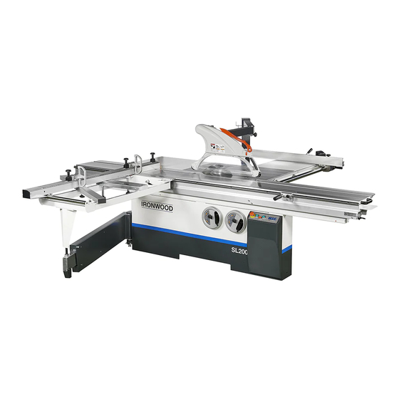
SLIDING TABLE SAW
ORIGINAL OPERATING MANUAL
■
Before you use the machine , please carefully read the manual and obey all related notes for
safety and instructions.
■
This manual is a part of the machine , so please make sure to include this manual when the
machine is moved , transferred and sold.
SL 200
Advertisement
Table of Contents

Subscribe to Our Youtube Channel
Related Manuals for Ironwood SL 200


Summary of Contents for Ironwood SL 200
- Page 1 SLIDING TABLE SAW SL 200 ORIGINAL OPERATING MANUAL ■ Before you use the machine , please carefully read the manual and obey all related notes for safety and instructions. ■ This manual is a part of the machine , so please make sure to include this manual when the...
- Page 3 Thank you very much for your purchasing our SCORING TABLE SAW. For personal safety and excellent performance of the machine, please first carefully read the Operating Manual and other attachments to be familiar with the machine’s functions, safe instructions and notes. NOTES 1.
- Page 4 1. If you are not fully familiar with the machine’s operation, you must be instructed by your supervisor or qualified person. 2. If the running direction of the saw is wrong, it will cause danger. 3. The anti-skid floor cushion is put at the operator ’s standing area and the machine’s working area.
- Page 5 To secure safety Please make sure to carefully read the safe instructions to be familiar with the machine’s functions, safe information and notes before you start, run & start the machine. Please carefully read the trouble-shooting guide to be familiar with the machine’s functions, safe information and notes before you repair or check the breakdown.
-
Page 6: Table Of Contents
CATALOG SAFE INSTRUCTIONS EXPLANATION OF WARNING SIGN 1.BRIEF INTRODUCTION TO MACHINE 1-1 SPECIFICATION 1-2 MACHINE DIMENSION 1-3 FEATURES 1-4 INDICATION 1-5 RIVING KNIFE SPECIFICATION 1-6 PROTECT SWITCH ON THE END OF SLIDIN TABLE 2.SPARE PARTS ASSEMBLY UNIT 2-1 TRANSPORT 2-2 SLIDING TABLE UNIT 2-3 CROSSCUT TABLE UNIT 2-4 CROSSCUT FENCE UNIT 2-5 RIP FENCE UNIT... - Page 7 6-4 TABLE UNIT MAIN TABLE 6-15 SLIDING TABLE 6-16 CROSSCUT TABLE 6-19 EXTENSION TABLE 6-20 6-5 FENCE UNIT RIP FENCE 6-21 RIP FENCE DIGITAL DISPLAY 6-23 6-25 CROSSCUT FENCE CROSSCUT FENCE DIGITAL DISPLAY 6-27 MITER FENCE 6-30 6-6 SAFETY GUARD UNIT SIMPLE TYPE SAW GUARD 6-31 DUST-COLLECTING FASTENING RACK...
-
Page 8: Brief Introduction To Machine
1 . BRIEF INTRODUCTION TO MACHINE SPECIFICATION Technical data , Standard and optional equipment Unit : mm MODEL SL200 ITEM Rectifed cast iron fixed table dimension 570 × 1000 Sliding table dimension 380 × 2600 Main saw blade 305 (12") Main saw blade 355 (14") / Max. -
Page 9: Features
Cutting depths Cutting depths Sliding table cutting lengths Witch or w itout scoring saw blade Saw blade diameter 255(10") 305(12") 355(14") 0~55 mm 0~80 mm 0~105 mm 1900 mm (74.8 in) 1800 mm (70.87 in) Cutting depths at 90° (0~2.16 in) (0~3.15 in) (0~4.13 in) 2600 mm (102.36 in) -
Page 10: Indication
INDICATION 1- 4 Fig.1 Fig.2 Main blade speed Fig.3 Fig.4 Note Fig. 1:the main saw's size and running direction. Fig. 2:the main saw's size and running direction. -
Page 11: Riving Knife Specification
RIVING KNIFE SPECIFICATION Riving knife A : Available Main Saw diameter range. B : Riving knife depth. C : Luxurious riving knife. WARNING Prior to setting the riving knife, check whether it matches the saw blade diameter and body thickness. Always switch off the main switch prior to setting the riving knife preventing cause danger. -
Page 12: Protect Switch On The End Of Slidin Table
1 - 4 PROTECT SWITCH ON THE END OF SLIDIN TABLE A: Should you accidently press the ON button when changing saw blade, this protect switch is able to keeps the saw blade standstill so that the operator won’t get hurt. -
Page 13: Spare Parts Assembly Unit
2 .SPARE PARTS ASSEMBLY UNIT TRANSPORT TRANSPORT WOODEN CRATE WARNING To transport the machine, please request the person who has licenses of gantry, crane, lift truck, etc, to operate. The weight of machine is listed in the chapter 2-1 and 2-2. After confirming, please proceed as per the weight. To suspend and move the machine, please follow Notes of Chapter 2-1 and 2-2 to operate. - Page 14 TRANSPORT MACHINE The machine's net weight is about : Body (Cutting width 1m):76 0kgs Body (Cutting width 1.3m):77 0kgs Body (Cutting width 1.5m):780kgs Please refer to Chapter 1-2 for detailed data. 1 . USE LIFT TRUCK TO TRANSPORT MACHINE WARNING ●The lift truck must be able to bear to least 5tons.
-
Page 15: Sliding Table Unit
SLIDING TABLE UNIT ASSEMBLE ★Prior to setting sliding table , release the trimming planks (Fig.2-2-1). Ensure the trimming planks releasing before 1 working operation or the machine damaged. Put the sliding table on the contact surface Clean the contact surface of the and tightly against the adjusting screw. - Page 16 ADJUST Adjust the adjusting screws at two sides Loosen 3 fixing screws. of the machine to make the sliding table parallel to the saw blade and keep the gap as shown in the left drawing with the working table. After assembling, tighten the fixing screws.
-
Page 17: Crosscut Table Unit
CROSSCUT TABLE UNIT ASSEMBLE Put one end of the crosscut table into Put the other end on the round rod the projected round rod of the of the sliding table and put the expansion pipe ( apply the lubricating locking bar under the round rod of oil to the balls to prevent friction from the sliding table. -
Page 18: Crosscut Fence Unit
CUOSSCUT FENCE UNIT ASSEMBLE Put the crosscut fence into the Press down the handle to fix the crosscut fence. positioning point of the crosscut Note : If the crosscut fence is moved, table. please first adjust the perpendicularity of fence and ADJUST saw blade before use. -
Page 19: Rip Fence Unit
RIP FENCE UNIT ASSEMBLE Use the gage to measure the parallelism of Lock the screw on the round rod the rip fence and the main saw blade. into the rihgt side of the working Measuring way : The rip fence is fixed and table, put into the rip fence base, the sliding table is pushed to the left. -
Page 20: Extension Table
ADJUST After the rip fence is moved, if the moving size and the target size have slight difference, the following is the operating way of the micro-knob : 1. Pull the handle (Part A) upwards, move the rip fence to near the target size. - Page 21 Measure if the main table Adjust and fasten 2 adjusting bolts extension and the main table and 3 metal sheet fixing screws. become a plane. ASSEMBLE WIDTH EXTENSION TABLE Lock the support into the back of Loosen 3~5mm of 4 metal sheet the machine.
-
Page 22: Dust Guard Unit
DUST GUARD UNIT SIMPLE TYPE SAW GUARD Install the dust collection fixing Install the dust collecting hood on the ribbing knife, connect dust collection rack and the dust collection pipe hose, use clamp to fix the hose as onto the left side of the machine shown in above drawing. - Page 23 LUX SAW GUARD Install the dust collection fixing rack Adjust the guard parallel with the onto the left side of the machine as saw and tighten the screw as shown in above drawing. shown in above drawing. WARNING Before you install the safety guard, please lower the saw under the table.
- Page 24 WARNING Before the machine is used to cut workpiece, Please make sure the dust collector work normally. Note1 : The required air speed at the end of flexible tube is 30~34m/sec. The required air volume of the machine is 1220~1390 m³/hr. (43,000~49,000 cuft/hr) Note2 :Antistatic and electrically conductive hoses only.
- Page 25 CHANGE SAFETY GUARD Push up the lock button on the saw guard loosen the saw blade shield to outward can be replacement. WARNING ● In order to prevent the saw blade touch the saw shield during the replacement, kindly downward the saw blade to the bottom and move the saw guard unit to the upward.
-
Page 26: Miter Fence Unit
MITER FENCE UNIT ASSEMBLE Put the slide block on the bevel Lock the fixing block on the sliding cutting fence into the round rod of table. the sliding table. ● Tighten knob A to fasten the center point of bevel cutting fence. -
Page 27: Riving Knife Unit
RIVING KNIFE UNIT ADJUST ● Loosen the fixing screw on the Measure the relative size of the riving knife base. riving knife and saw blade. ● Adjust the 3 adjusting screws at WARNING the two sides of the fixing screws as After adjustment of the riving knife the projected place shown in the above drawing. -
Page 28: Main Saw Unit
MAIN SAW UNIT 2-10 CHANGE MAIN SAW BLADE DANGER ● Before changing saw blade, please confirm if power is closed. ● At changing saw blade, please put on the protective film to avoid any damage during changing. Push the sliding table towards the Open the saw blade guard. - Page 29 CHANGE SPINDLE'S ROTATING SPEED DANGER Change spindle's rotating speed, please confirm if power is closed. Turn the saw blade’s lifting hand Open the service door at the back wheel to lower main saw blade to of the machine, loosen the adjust the bottom.
- Page 30 ADJUSTMENT FOR MAIN SAW HEIGHT AND TILTING. Hand wheel operation A. Hand wheel for main saw blade height adjustment. (As displaying in the diagram, the arrow direction is downward, on the contrary, upward.) B.Hand wheel for main saw blade tilting adjustment.
-
Page 31: Scoring Saw Unit
SCORING SAW UNIT 2-11 OPERATE A : Forward/backward adjusting knob. B : Forward/backward fixing knob. C : Lifting displacement knob. D : Lifting fixing knob. CHANGE DANGER ● Before changing the saw, please make sure if the power is closed to void danger. ●... -
Page 32: Operating Unit
3 . OPERATING UNIT POWER CONNECTION DANGER ● Power connection must be done by the qualified electronic engineer. ● The machine must have an earth wire to prevent electric leakage from happening electric shock and even death. Connect the wiring step : 1.Make sure the voltage of the machine conforms to your company's power. - Page 33 OPEN POWER CONTROLLING BOX Use the specific tools enclosed in According to the Fig marked the tooling box. direction can be open the electric cabinet door. DANGER Please make sure the power is turned off before opening the electric cabinet door. Notes for wiring : 1 .
-
Page 34: Operation Of Control Panel
OPERATION OF CONTROL PANEL EXPLANATION OF MAIN KEYS Digital display A. Emergency stop button Urgently shut down the machine’s power. B. Main saw start button Start main saw. C. Scoring saw start Start scoring saw. button Stop the main saw and scoring saw.. - Page 35 OPERATING INSTRUCTION FOR CORRECTING CURRENT DIMENSION Current figure show on the display is 21.5 To correct in 35.1, the steps to operate are as the following diagrams demonstrated. DIAGRAM.3 Step 4: The display Press button once shows 21.5 and press button 5 times.
- Page 36 5. DESCRIPTION OF PARAMETER SETTING P2.P3 angle setting .P2 default parameter is 0111 which means 4 digits prior to decimal.P3 default parameter is 8300 which means 4 digits after decimals and therefore , the angle parameter is 0.011183.(should there be deviation for parameter please kindiu adjust p3.) WARNING 1.The operators have to pay their attention not to make any change.
- Page 37 Step 6: Step 11: Press button once and Press button press button once. , The display shows The display shows 101.1 000.0 and 4th digital and 3th digital (1) flash. is flashing. Step 12: Step 7: Press button 2 times and Press button once and press...
-
Page 38: Clean & Maintain Unit
4.CLEAN & MAINTAIN UNIT MAINTENANCE OF THE SLIDING TABLE ● Clean the contact surface (Surface A) of upper slide base and lower slide base. ● Clean the contact surface (Surface B) of lower slide base and the roller. ● Periodically clean above contact surfaces to keep long-term accuracy of machine. - Page 39 SAFETY CHECK 【 】 WARNING Do safety check at least twice every week to secure emergency switch's normal function. CHECK OF EMERGENCY STOP SWITCH Steps of check : 1. Connect to power, start the main saw blade and the scoring saw to make the machine run.
- Page 40 5.TROUBLE SHOOTING GUIDE T R O U B L E C H E C K C A U S E A C T IO N C h e c k i f p o w e r A C 5 V a n d In p u t c o r r e c t v o lta g e .
- Page 42 FIG.NO. DESCRIP TION SPEC FIG.NO. DESCRIP TION SPEC 20211001-0 Saw frame body 401072033 Setscrew M6X6 20211002-0-56 Rear door 416010045 Power Switch ZH-28-2-80-BY 20213002-0 Bearing base LST-A011 Mark 20413001-0 Bearing base 416010046 Emergency button ZB4-BS844+ZB4-BZ102(1B) 402090002 Aluminum Hinges CL-208 20213005-0 Support adjusting baes 401022028 Cap scre M5x12...
- Page 43 FIG.NO. DESCRIP TION SPEC FIG.NO. DESCRIP TION SPEC LST-G001G Crosscut Swing Arm P26/P32 402120001 Magnet Ø12x5 S03302 LST-G004 Adjustment shaft 403015133 Ball Bearing 6203-LLU TPI ST-J014K Roller/Ball bearing 6003-ZZ TPI LST-G003 Way wipers 401252012 Ext Retaining Ring S-17 LST-G002 Locating plate ST-J014L Roller/Ball bearing 6202-ZZ TPI...
- Page 45 FIG.NO. DESCRIP TION SPEC FIG.NO. DESCRIP TION SPEC LST-B002 Adjust shaft 20225001-0 Scraper 403015132 Ball Bearing 6202 ZZ LST-B002A Adjust shaft 401252010 STW-15 LST-B001B Rotary base Retaing rings for shaft LST-B009 Cover LST-B004 Fixed block 20222005-A Lower blade cover LST-B005 Fixed Pole LST-B013A Join bar...
- Page 47 FIG.NO. DESCRIP TION SPEC FIG.NO. DESCRIP TION SPEC 20234001-A Riving Knife 27 NLST-C056 Riving knife's front fixed block 20234002-0 Bulletproof claw 28 NLST-C054 Riving knife's rear fixed block 20234003-0 Connect film 29 401200032 Roll Pin D13x60 20234004-0 The rings 30 401022055 Cap scre M6x20 401052118...
- Page 49 FIG.NO. DESCRIP TION SPEC FIG.NO. DESCRIP TION SPEC LST-E015 Connecting block LST-E006 Worm shaft 401150005 Lock washer Ø10 401052118 Counter sunk head cap screw M5x12 401022104 Cap screw M10x25 LST-E004 Cover 401200015 Fixed Ring Ø8x20 401022055 Cap scre M6X20 NST-406-1-0 LST-E009A Housing RS-3021...
- Page 51 FIG.NO. DESCRIP TION SPEC FIG.NO. DESCRIP TION SPEC LST-D008A Adjustment shaft 401103003 Lock nut LST-D010A Adjustment shaft 401072083 Set screw M12x40 LST-D014 Sleeve ring 401072054 Set screw M8x20 LST-D017A Washer LST-D001 Scoring S pindle Housing 401072136 Set Serew M5x4 403010305 Ball Bearing 6204-LLB-CM LST-D022A...
- Page 53 FIG.NO. DESCRIP TION SPEC FIG.NO. DESCRIP TION SPEC LST-C015A Shaft 401230005 8x7x32 LST-C016A 20233011-0 lnspection seat Main Motor Pivot Plate LST-C033 End caps 401150003 Lock Washer Ø6 Sew serew 401072085 M12x50 401022051 Cap scre M6x12 401101007 Hex Nut 20233012-0 Belt posltlon detector plate 401150006 Lock washer Ø12...
- Page 54 FIG.NO. DESCRIP TION SPEC FIG.NO. DESCRIP TION SPEC LST-D005 Pivot axis Motor LST-D007A Washer 401140014 Washer Ø12 401150005 Lock Washer Ø10 401150006 Lock Washer Ø12 Cap scre 401022105 M10x30 401011023 Hex Bolt M12x55 NST-104-0-0 Spring 401101007 Hex Nut 401200019 Spring pin Ø6x32 ST-I032 Pulley...
- Page 55 FIG.NO. DESCRIP TION SPEC FIG.NO. DESCRIP TION SPEC LST-F001G Main Table Model 350 11 ST-N436 Rip Fence Scale 1.3m、1.5m LST-F003A Table Insert 12 401052134 M6x30 Count er sunk head cap screw 401072135 Set screw M16x130 13 ST-O026 S cale base rubber guide 401071131 Set Screw M16x150...
- Page 57 FIG.NO. DESCRIP TION SPEC FIG.NO. DESCRIP TION SPEC ST-K302G Support Base ST-311 Fixed Pillar ST-K041A Stop block ST-K313A Connect Block 401022076 Cap screw M8-16 401104003 Cap Nup ST-K002 Lock Block 401103005 Lock Nut 401052131 M6x16 401022057 Cap screw M6x30 Counter sunk head cap screw ST-K316 Positioning block ST-K312...
- Page 59 FIG.NO. DESCRIP TION SPEC FIG.NO. DESCRIP TION SPEC 20274005-0 Crosscut table ST-M019 Long cross-support LST-G027 Support frame ST-M020 Clampingn element 401052152 M10x25 402070005 Knob bolt HS50AM850 Counter sunk head cap screw 401140010 Washer Ø6 ST-M017 Square tube plug 70x40x3t 401150003 Lock Washer Ø6 401010038...
- Page 60 FIG.NO. DESCRIP TION SPEC FIG.NO. DESCRIP TION SPEC LST-F014B Width extension 1.3m 401140002 Washer Ø5 LST-F011 Small Extension Table 401150002 Lock Washer Ø5 ST405-505 Hex screw 401022033 Cap screw M5x25 401101007 Hex Nut 401101012 Hex Nut 401151002 Safety Washer Ø8 401140020 Washer Ø16 401150003...
- Page 62 FIG.NO. DESCRIP TION SPEC FIG.NO. DESCRIP TION SPEC LST-F002M Slide rail 1.3M ST-Q011A Fixed shaft 401072135 Set screw M16x130 402070006 Hand Knobs HS50AM1030 401102001 M16x8t 401071025 Set serew M5x10 Hexagon Thin Nut 401140007 Washer Ø16 ST-K044 Sliding wheel adjusting block 401011015 Hex Bolt M8x12...
- Page 64 FIG.NO. DESCRIP TION SPEC FIG.NO. DESCRIP TION SPEC ST-N058U-01 Fence scale base 401051110 Counter sunk head cap screw M4x12 LST-G023 Fixed axis ST-N107 Set screw 401140010 Washer Ø6 401101005 Hex Head Bolt 401150003 Lock Washer Ø6 414080008 Hole plug HP-9 402140001 Swing bolts ST-N054A...
- Page 66 FIG.NO. DESCRIP TION SPEC FIG.NO. DESCRIP TION SPEC ST-N058V-01 Fence Scale Base ST-N102 Link 401200008 Spring Pin Ø6x40 401022027 Cap scre M5x10 20275007-0 Offset scale 401140002 Washer Ø5 401053101 M3x5 401101003 Hex screw Countersink Hend Screw ST-N059 Fixing sheet ST-N066E Lock slide base 20275008-0 Positioning column...
- Page 67 FIG.NO. DESCRIP TION SPEC FIG.NO. DESCRIP TION SPEC LST-H004A Lower Support Arm(350、400) 1.3m 401072055 Set screw M8x25 LST-H005A Upper Support A rm(350) 401140010 Washer Ø6 401150003 Lock nut Ø8 401150003 Lock Washer Ø6 ST-D525-0-1 Fasten Base 401022056 Cap screw M6x25 401022076 Cap screw M8x16...
- Page 68 FIG.NO. DESCRIP TION SPEC ST405-609 Rotery Arm 1.3m ST-D027B Connect Block 401022076 Cap screw M8x16 ST-D527-0-0 Bush ST-D529-0-1 Fixed Base ST-D531-0-0 Lock Shaft 402070002 Knob HS50AM8 401140004 Washer Ø8 401150003 Lock nut Ø8 401022080 Cap screw M8x30 401010019 Hex Head Bolt M8x20...
- Page 70 SPEC SPEC FIG. NO. DESCRIP TION FIG. NO. DESCRIP TION ST-Q047B Push Stick 27 401022058 Cap Screw M6x35 ST-D311A Left Safety Guard 28 401022056 Cap Screw M6x25 ST-D314 Open/Lock Button 29 401022082 Cap Screw M8x40 ST-D311B Right Safety Guard 30 401251017 Retain Ring φ22 ST-D303A...
- Page 71 FIG.NO. DESCRIP TION SPEC FIG.NO. DESCRIP TION SPEC 416071037 transformer 160VA 416230001 Ground plate 416081001 Bridge Rectifler KBPC 2506 416023001 Rely MY-2NJ AC220V Electromagnetic contactor 416021128 LC1-D25(M7) 416051014 Fuse Holder DF102 10x38 2P 416240001 Auxiliary contact LADN11 416052025 lnput fuses 4A GG 416021109 LC1-D09(M7)
- Page 72 FIG.NO. DESCRIP TION SPEC 414041022 Terminal Block(Active end) PP-H4/14 414041021 Terminal Block PT4/1P 414041018 Terminal Block PT-6 414041020 Terminal Block PT-4 414041017 Terminal Block PT-2.5 416230001 Ground plate...
Need help?
Do you have a question about the SL 200 and is the answer not in the manual?
Questions and answers