Advertisement
Quick Links
Advertisement

Related Manuals for Avision DF-1911B


Summary of Contents for Avision DF-1911B
- Page 1 Sheet-fed Scanner User’s Manual Regulatory model: DF-1911B Avision Inc.
- Page 2 Warranty The information contained in this document is subject to change without notice. Avision makes no warranty of any kind with regard to this material, including, but not limited to, the implied warranties of fitness for a particular purpose. Avision shall not be liable for errors contained herein or for incidental or consequential damages in connection with the furnishing, performance, or use of this material.
- Page 3 User’s Manual Federal Communications Commission (FCC) compliance information statement Part 15 This equipment has been tested and found to comply with the limits for a Class B digital device, pursuant to Part 15 of the FCC Rules. These limits are designed to provide reasonable protection against harmful interference in a residential installation.
- Page 4 RED (Radio Equipment Directive) (2014/53/EC) CE compliance of this product is valid if powered with the correct CE-marked AC adapter provide by Avision. This product satisfies the Class B limits of EN55032, EN55035, and safety requirements of EN62368-1. *This machine is certified as Class 1 LED product.
- Page 5 ® As an ENERGY STAR Partner, Avision Inc. has determined that this product meets the ENERGY STAR guidelines for energy efficiency. System Requirements ®...
- Page 6 User’s Manual Product Safety Guide Please clearly read all these instructions, and follow all instructions and warnings before installing and using the device. The following indications are used in this document to obviate any chance of accident or damage to you and/or the device. Indicates potentially hazardous situations, which WARNING if instructions are not followed, could result in...
- Page 7 User’s Manual Do not place or store the device or its AC power adapter: Outdoors Near excessive dirt or dust, water, or heat sources In locations subject to shocks, vibrations, high temperature or humidity, direct sunlight, strong light sources, or rapid changes in temperature or humidity Do not use the device with wet hands.
- Page 8 User’s Manual CAUTION: Do not attempt to operate the battery in temperature outside the range of -20°~60° C. If so, this may cause cracking, rupturing, bursting, emission of flame or expulsion of molten metal to the outside of the equipment enclosure. Note the operating temperature for the battery is from -20°...
- Page 9 User’s Manual IMPORTANT NOTICE: FCC Radiation Exposure Statement: This equipment complies with FCC radiation exposure limits set forth for an uncontrolled environment. This equipment should be installed and operated with minimum distance 20cm between the radiator & your body. To maintain compliance with FCC RF exposure compliance requirements, please avoid direct contact to the transmitting antenna during transmitting.
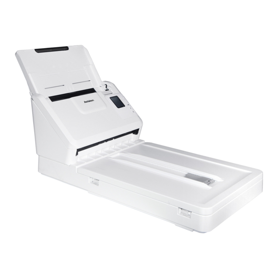
- Page 10 User’s Manual 1. Introduction Congratulations on your purchase of the high speed document image scanner. With this scanner, you can you scan your multi-page documents from the auto document feeder at a rated speed or scan irregular single-page document from the flatbed.
- Page 11 2. Please unpack the packing carefully, and check the contents against the checklist. If any items are missing or damaged, please contact your dealer immediately. 3. * The availability varies according to your scanner model. 4. To access more service supports, visit www.avision.com to register your Avision’s product.
- Page 12 User’s Manual Front View Extension Paper Guide Screen with Paper Tray Up/Down Buttons Paper Guide Scan Button Paper Stopper Cancel Button Power Button Document Cover Part Name Description Extension Can be pulled out and adjusted to the size of the document being scanned. Paper Width Slide it up or down to fit your paper Switch...
- Page 13 User’s Manual 1.3 Control Panel Item Description Display the scanning and error status. Display Button Panel. Used to scroll up and down to select your function button via the software application - Button Manager V2. Used to select an item.
- Page 14 User’s Manual 1.4 Rear View Power Jack LAN Port USB Port Part Name Function LAN Port Used to connect to network. USB Port Used to connect to your computer. Power Jack Used to connect the AC adapter to the scanner.
- Page 15 User’s Manual LCD Display USB Connection After installing the scanner driver and connecting the scanner to your computer via the USB cable, the following LCD display will be prompted: Indicates successful USB connection 1. USB You may use a TWAIN-compliant application such as Xerox Capture Tool to start a scan.
- Page 16 User’s Manual Indicates Button # and Button Name Press (Scan button), the paper starts feeding into the scanner and the scanned image will be sent to your specified destination. Refer to chapter 6 – Using the Buttons on how to press the button to complete a scan.
- Page 17 User’s Manual Status Bar/Options Icon/Option Status Indication Successful USB connection between PC and scanner Successful Wi-Fi AP (Access Point) Connection Turn on Wi-Fi connection. Successful ethernet cable connection. Select to refresh the connection status. Select to access more settings. Select to use WPS (Wi-Fi Protected Setup) to connect to a wireless access point which supports WPS.
- Page 18 User’s Manual 1.6 Removable Parts Friction Roller ADF Roller...
-
Page 19: Scanner Installation
User’s Manual Scanner Installation 2.1 Precautions Keep the scanner out of direct sunlight. Direct exposure to the sun or excessive heat may cause damage to the unit. Do not install the scanner in a humid or dusty place. Be sure to use the proper AC power source. - Page 20 User’s Manual 2.2 Connecting to Power Before connecting, make sure the power switch is off. Plug the small end of the power adaptor into the power jack of your scanner. Insert the other end to an appropriate power outlet. 2.3 Turning on the Power Press the Power Switch button on the front panel, the Power LED will flash.
- Page 21 User’s Manual 2.4 Installing the Scanner Driver Note: To ensure your computer can identify the USB scanner, please install scanner driver first before connecting the scanner to your computer. The scanner driver contains TWAIN, ISIS and WIA driver. After the installation of scanner driver is completed, this scanner allows you to scan via a TWAIN, ISIS, or a WIA interface.
- Page 22 User’s Manual Contents on the installation graphic: Install Scanner Driver: To communicate with your scanner, you need to install the scanner driver. Install Button Manager V2: To use the buttons on the scanner, you need to install Button Manager V2. To ensure Button Manager V2 works properly, please FIRST install scanner driver before installing Button Manager V2.
- Page 23 User’s Manual 2.5 Connecting to Computer Connect the square end of the USB cable to the USB port of your scanner. Connect the rectangle end to the USB port at the rear side of your computer. Note: The scanner is designed with a USB 3.2 Gen 1x1 interface to ensure the optimal speed.
- Page 24 User’s Manual 2.6 Connecting to a Network Cable Connect one end of your network cable to an available port of the switching hub of your LAN. Connect the other end to the LAN port marked at the back of the product as shown.
- Page 25 The Network Setup Tool is included in the supplied software CD. Start [Virtual Scanner Link] by choosing Start>All Programs>Avision Virtual Scanner>Virtual Scanner Link. The main window will be displayed and the scanners in your network will be searched automatically. In a few seconds, the result including the scanner model and scanner’s IP address will be displayed as shown.
- Page 26 User’s Manual After the scanner has been connected successfully, launch your TWAIN-compliant image-editing software application to start a scan (Figure A). Or simply press the [Scan] button on the scanner to start a scan (Figure B). Figure A Figure B...
- Page 27 User’s Manual Note: The VSL program allows multiple users to connect to the network scanner at anytime. Yet, the scanner operation can be used by one user at a time. If the network scanner is being used by other user, you will be prompted with a message to connect the scanner later.
- Page 28 User’s Manual The connection is always enabled, whether the scanner enters into the sleeping mode or turns off and on again. VSL will automatically detect the previously connected scanner and connect again. [Automatically searching and connecting device]: Check this option and enter your time (1~5 min.) to allow the VSL to reconnect to the device every specified minute(s) if the device has been woken up during sleep mode or the device has been turned off and on again.
- Page 29 (Refer to the preceding section 2.3~2.7) On your computer, start [Virtual Scanner Link] by choosing Start>All Programs>Avision Virtual Scanner>Virtual Scanner Link. The main window will be displayed and the scanners in your network will be searched automatically.
- Page 30 User’s Manual Use the Arrow key to select your desired Button No. or destination and then press (OK). The scanner starts feeding your paper and the scanned image will be sent to your specified application or destination. 2-12...
- Page 31 In VSL main window, connect the scanner. Open Avision Capture Tool by choosing Start>All Programs>Avision XXX Scanner>Capture Tool. Select the scanner model and then the main window will be displayed.
- Page 32 User’s Manual Press (Scan button), the paper starts feeding into the scanner and the scanned image will be displayed. Note: The timeout for the lock status is 60 seconds. If you wish to cancel the lock status within timeout, press ...
- Page 33 User’s Manual 2.10 How to View Scanner’s Detailed Information 1. On the scanner, press (Down arrow) to select [More Settings] and then press (OK) to confirm. The screen including [Wi-Fi], and [Information] option will be displayed. 2. Select [Information], and press (OK), and then choose your desired option.
- Page 34 User’s Manual Counter Information : Counter : The scan count of ADF roller and Friction Roller Total: Scanner Wi-Fi Wi-Fi Wi-Fi Direct Link ADF: Ethernet Counters Friction Roller: Information Clean Mode 2-16...
- Page 35 2.11 How to Change the Scanner’s IP Address and Device Name Start [Virtual Scanner Link] by choosing Start>All Programs>Avision Virtual Scanner>Virtual Scanner Link. The main window will be displayed and the scanners in your network will be searched automatically. Click the scanner’s IP address as indicated. The scanner’s web page will be displayed.
- Page 36 User’s Manual Note: You may also use the webpage to change your connection type, authentication method, or connect to other access point or router which supports the WPS connection. 2-18...
-
Page 37: Completing Your First Scan
User’s Manual 3. Completing Your First Scan Placing Your Document on the Flatbed Open document cover. Place your document FACE DOWN on the document glass and align the document to the reference mark as indicated. Close document cover. - Page 38 User’s Manual 3.2 Loading Your Paper 3.2.1 Notice on Using the ADF Before using the ADF, please make sure that your paper meets the following specifications: Document (s) can range in size from 74 x 52 mm (2.9 x 2 in.) to 216 x 356 mm (8.5 x 14 in.) ...
- Page 39 User’s Manual 3.2.2 Loading Your Document in the ADF Paper Tray Fanning Your Document Note: To avoid occasional multi-feeds or paper jams, please fan your documents and align the top edges before feeding them into the scanner. 1. Hold both ends of the documents and fan them a few times.
- Page 40 User’s Manual Document Feeding 1. Unfold the document feeder and its extension. 2. Unfold the output tray and raise the paper stopper. ...
- Page 41 User’s Manual 3. Raise the paper guide to hold your multi-page document. 4. Load the stack of document face down with the top of the pages pointing into the feeder. 5. Verify that the paper guides are aligned with the edges of the stack.
- Page 42 User’s Manual 3.2.3 Scanning a Stack of Document with Various sizes and Weights When scanning a batch of documents with different sizes and weights, be sure to follow these guidelines to avoid a skewed image or a paper jam: 1. Align the documents TOP EDGE first in the sequence of paper size from large to small.
- Page 43 User’s Manual 3. Align the edges of the documents by tapping the bottom of the stack against the table top. 4. Center these pages in the document feeder and make sure that the edges of page of the largest size slightly touch the Paper Guide.
- Page 44 Verifying Your Scanner Installation To verify if your scanner installation is correct, Avision provides you a useful test program called Avision Capture Tool. With this tool, you can perform simple scans and view the captured images. In addition, it helps you complete your scan at a rated speed.
- Page 45 User’s Manual Actual Page Size File Format Save File Path Scan Setup Choose your desired file format from the File Format drop down list box. (Default is JPEG, other choice includes TIFF, MTIFF, PDF, MPDF, GIF, and BMP.) The supported file formats vary depending on your scanner model.
- Page 46 User’s Manual Image Selection From the Image Selection Box, choose your desired image type for your scanned image. (Default is Front B&W) If you have a duplex scanner, choose Front and Rear to scan both sides of your document. Click OK to quit the Scanner Properties dialog box. (To learn more details about the Scanner Properties dialog box, please see the subsequent chapter, Using the Scanner Properties Dialog Box.)
- Page 47 User’s Manual Display View Thumbnail View 11. You can view the scanned image in Fit Page ( ) or Actual Size (100%) button ( ) from the Viewing toolbars at the right side. 12. Click the Close box or Quit from the File menu to exit the Scan Validation Tool.
- Page 48 User’s Manual A Glance of the Scanner Properties Dialog Box 1. Tab Options Choice: Image, Compression, Color Dropout, Paper, Multi-Feed Detection, Preview, Options, Settings, Information. 2. Image Choose your image type and the side of Selection Box document you wish to scan. Options vary based on type of scanner.
- Page 49 User’s Manual Using the Scanner Properties Dialog Box The Scanner Properties dialog box allows you to configure the scanner’s settings. It consists of several tabbed windows each of which will be described in this chapter. Note: In this chapter, all options are available based on a duplex (double-side) scanner.
- Page 50 User’s Manual 4.1 Buttons on the Scanner Properties Dialog Box The buttons on the Scanner Properties dialog box Buttons Description Defaults Click the Defaults button, the factory default settings will be shown on each tab. Cancel Click the Cancel button to leave the Scanner Properties dialog box.
- Page 51 User’s Manual The following table shows the default settings: Tab name Default settings Image Image:Front B&W Binarization:Dynamic Threshold Resolution:200 dpi Invert:Blank on White Scan Source:Auto Document Feeder Threshold:None Brightness:None Contrast:None Compression None Color Dropout None Paper Cropping:Automatic Deskew:Yes Orientation:Portrait OverScan:0.00 Note: The availability of this option varies due to scanner model.
- Page 52 User’s Manual Showing or Hiding Tabs The [Scanner Properties] dialog box is displayed in default with three basic tabs - Image, Paper, and Information. To show more tabs, click the [Scanner Properties] icon to access more scan settings. To show more tabs, Click the [Scanner Properties] icon ( ) on the upper left corner, and choose [Tab] to show available tab names.
- Page 53 User’s Manual...
- Page 54 User’s Manual The Image Tab The Image tab allows you to choose the front side and (or) the rear side of your document, the type of image, and to set several basic scan settings. Note that except for the resolution, you can set individual scan settings for the front side and the rear side.
- Page 55 User’s Manual 4.3.1 The Image Selection Box The Image Selection box includes the image type and document side option. you wish to scan both the front side and the rear side of your color document, you can check both Front Color and Rear Color at the same time.
- Page 56 User’s Manual Example 2:Scanning a two-sided color document, one in B&W, the other in color Side/Image Front Rear Selection Image Type Description Color Choose Color if you wish to scan a color image for your original in color. Gray Choose Gray image if your original contains actual shades of gray.
- Page 57 User’s Manual Front/Rear Auto Color Detection: Click to automatically detect and scan the front or the rear page of your color document in color image mode. If your document is in colors, the scanner will automatically scan the document into a color image. If your document is non-color, you can choose the output to be either B&W or Gray from the Non-Color Selection option.
- Page 58 User’s Manual Sensitivity of Auto Color Detection If your documents contain primarily B&W text and small amount of light or pale colors and you do not wish them to be recognized as color image to save the file size, you can increase the sensitivity value by moving the bar to the right to let these images to be detected as B&W.
- Page 59 User’s Manual Same settings on both sides: Click to apply same scan settings for both sides of your documents. After checking this option, any settings you have changed will automatically applied to both the front side and the rear side. For example, if you choose your ideal resolution to be 300 dpi, this will be applied both to the front side and rear side of your document.
- Page 60 User’s Manual 4.3.2 Other Image Options Binarization This is the process of converting a grayscale or color image to a bi-tonal image. There are several different methods of performing this conversion. Options: Dynamic Threshold, Dynamic Threshold (AD), Fixed Processing, Halftone 1~5, Error Diffusion.
- Page 61 User’s Manual Fixed Processing: Used for black-and- white and other high contrast documents. A single level is set to determine the black- and-white transition. The threshold is programmable over the entire density range. Fixed Processing sets Contrast to 0. If Fixed Processing is selected, Contrast is not available.
- Page 62 User’s Manual Error Diffusion Image Dynamic Threshold (AD) Dynamic Threshold 4-14...
- Page 63 User’s Manual Threshold Used to convert a grayscale image to a bi-tonal image. The value ranges from 0 to 255. A low threshold value produces a lighter image, and can be used to subdue backgrounds and subtle, unneeded information. A high threshold value produces a darker image, and can be used to help pick up faint images.
- Page 64 User’s Manual Gray Document Type: Choice: Normal, Photo, Document Three options of document type are provided when you choose Gray as the image type for your scanned document. Choice: Normal, Photo, Document. Document: Choose Document if your original contains pure text or a mixture of text and graphic since it is an optimal setting for regular business document.
- Page 65 User’s Manual Normal Photo Document (Threshold: 230) Normal Photo Document (Threshold: 230) 4-17...
- Page 66 User’s Manual Brightness Adjusts the lightness or darkness of an image. The higher the value, the brighter the image. Drag the slider to the right or left to increase or decrease the brightness. The range is from –100 to +100. Contrast Adjusts the range between the darkest and the lightest shades in the image.
- Page 67 User’s Manual Resolution A good control of the resolution results a good detail of an image that scans. The resolution is measured by dots per inch (dpi). Normally, the greater the dpi number, the higher the resolution and the image file size.
- Page 68 User’s Manual Invert Reverses the brightness and the colors in the image. The default setting is Black on a White background. Reverse mode is White on a Black background. For color images, each pixel will be changed into its complementary color at the command of Invert.
- Page 69 User’s Manual Scan Choice: Source Auto Document Feeder: Used to scan multiple pages. Flatbed: Used to scan a single page. For example, pages from newspaper clipping, paper with wrinkles or curls. Flatbed (book): Used to scan several inside pages from book.
- Page 70 User’s Manual Note: If you have purchased a duplex sheet-fed scanner, choose [Merge Two Sides] on the [Scan Source], then the scanner is able to scan both sides of your document and merge them into a single image. If “Merge Two Sides into One Image” is selected, its choice will be available including “Merge Horizontally”, “Merge Vertically”, “Merge Vertically (Back Side Flip)”, “Merge Horizontally...
- Page 71 User’s Manual Color The purpose of Color Matching is getting the Matching accurate color. This option uses the default parameters (ICC profile) to adjust the colors of the image. Choice: None, Document, Photo None: Choose “None” to disable this option.
- Page 72 User’s Manual 4.3.3 Scanning color images The following options are available for scanning color images. Brightness Contrast Resolution Invert 4.3.4 Scanning grayscale images The following options are available for scanning gray images. Brightness Contrast Resolution ...
- Page 73 User’s Manual 4.3.6 Editing Profiles The Scanner Properties dialog box allows you to change and save your frequently used scan settings into a profile. You can edit these profiles by renaming or deleting them. To add a new profile, Customize your settings. (For example, change your resolution, image type, cropping method, scan size, or other scan settings.) Click the Image tab and then choose “Profiles”...
- Page 74 User’s Manual To load a profile, From the Image tab dialog box, choose your favorable profile from the “Profiles” dropdown list box. Your favorable profile will be immediately loaded and displayed on Scanner Properties dialog box. To delete a profile, From the Image tab dialog box, click “Profiles”...
- Page 75 User’s Manual To rename a profile, From the Image tab dialog box, click “Profiles” to prompt the Edit Your Profile dialog box. Choose the profile you want to rename from the dropdown list box and then click the Rename button. Enter new name for the profile.
- Page 76 User’s Manual 4.4 The Compression Tab The Compression tab allows you to compress your scanned image and choose the level of compression. Bi-tonal images are normally compressed using CCITT standard called Group 4 (G4). Color and grayscale images are often compressed using JPEG technology.
- Page 77 User’s Manual Compression: To complete your scan at a rated speed, the scanned image is compressed by default during transmission. However, if you wish to obtain the highest image quality, you can choose to uncompress the image data before it is outputted. Scanned Scanned Image...
- Page 78 User’s Manual The Compression tab dialog box 4-30...
- Page 79 User’s Manual 4.5 The Color Dropout Tab 4.5.1 Color Dropout Selection The [Color Dropout] tab allows you to select either green, red, blue, or a color of your choice to remove the details of the selected color from a scanned image. This feature is used to sharpen your text when using OCR (Optical Character Recognition) software.
- Page 80 User’s Manual Auto/Remove Green Original (normal mode) Remove Red (normal mode) Remove Green (quality mode: Threshold: 18) Preview the color dropout result: To preview the color dropout result, please follow these steps: Click the [Scanner Properties] icon ( ) on the upper left corner, and choose [Tab] to show available tab names.
- Page 81 User’s Manual Move your cursor over the preview image. Your mouse cursor now becomes an Eyedropper. Click to select a color which you wish to remove. Click and hold your mouse button to view the result after removing the specified color. If the result is satisfactory, click [OK] to close the Preview window.
- Page 82 User’s Manual The Color Dropout dialog box 4-34...
- Page 83 User’s Manual To select a color on the Color palette, Click the Color Dropout tab from the Scanner Properties dialog box. Choose Gray or B&W from the Image Selection box and click “Custom” from the Color Dropout drop-down menu. The Color palette appears.
- Page 84 User’s Manual Move your cursor over the palette. The cursor becomes a cross sign. Click to choose a color. The RGB values are changed simultaneously. 4-36...
- Page 85 User’s Manual The Paper Tab The Paper tab allows you to define values relating to image output (i.e., Auto Crop or not, Scan Area, OverScan, Multi-Feed Detection). The Paper tab dialog box 4-37...
- Page 86 User’s Manual 4.6.1 Cropping Cropping allows you to capture a portion of the document being scanned. Choice: Automatic, Automatic (36”), Fixed to Transport, EOP (End of Page) Detection, Automatic Multiple, Relative to Documents. Options Description Automatic adjusts the cropping window Automatic according to different document sizes and automatically straighten a skewed...
- Page 87 User’s Manual Automatic This option allows you to place various Multiple sized documents such as photos, ID Cards, or business cards on the flatbed (if available) and lets you create multiple individually cropped images in one scan. Note: To correctly create multiple images, please make sure there is at least 12mm (0.5”) of space between each document.
- Page 88 User’s Manual The Adjustment option is available when Automatic is selected. Adjustment —adds a positive/negative margin value Top/Bottom or toward left/right of the image. Adjustment is used when the automatic document feeder is used. Adjustment reduces the possibility of corner clipping on skewed images.
- Page 89 User’s Manual Relative to Document: (used for batches of same-sized documents) This option allows you to crop different areas on your documents and deliver these images in B&W, Gray, or Color separately. For example, there are applications which require you to store the entire document in B&W and a part of the document in color to save storage space.
- Page 90 User’s Manual Click the Preview tab to display the Preview window. A black rectangular box appears to indicate the max. scan size your have just selected. The Image Selection A black rectangular Click the Preview button to view the entire image in low resolution to correctly crop your relative scan area.
- Page 91 User’s Manual A Cross Sign Relative Area Check the B&W image from the Image Selection box to scan the entire document. Click the Scan button to start scanning the document in two image types and sizes. (See the result in below.) The entire document in B&W The relative area in color 4-43...
- Page 92 User’s Manual 4.6.2 Other Paper Selection Carrier Sheet Mode: Check this option to automatically crop the scan window according to your document size when scanning non-standard document (fragile, irregular-size document) with a carrier sheet (optional). Note: The availability of this option varies due to scanner model.
- Page 93 User’s Manual For documents larger than A4/letter size, such as A3 Align the top of the document to the top of the Carrier Sheet (the printed section) and the folded portion to the right edge of the Carrier Sheet so that the document fits into the Carrier Sheet at the upper corner.
- Page 94 User’s Manual Notice: [Carrier Sheet] is available for the models that support the Carrier Sheet. Some functions are disabled when [Carrier Sheet] is checked. This option may not work properly on some applications. Scan Area Choose your desired paper size with the drop-down list box. Or you may select a custom paper size by clicking the Scan Area box and then click Add to include in the choice.
- Page 95 User’s Manual Long Page (<118”): When you need to scan documents whose length exceeds scanner maximum, please choose Long Page. Note if Long Page is selected, the Multi-Feed Detection will not be available. (Note: This option and the maximum allowable document length vary due to type of scanner.) When Long Page (<118”) is selected, be sure to specify your document size in the Length and Width field.
- Page 96 User’s Manual Transport Timeout Set the amount of time the scanner will wait and then start auto scan after the first scan job is completed. If you have many separate documents need to be scanned at the same scan settings, this feature is especially useful. The default is 0. The value ranges from 0 to 30 seconds.
- Page 97 User’s Manual Background This option allows you to set your scan Setting background. Choice: White Background, Black Background. Note: For a sheet-fed scanner with an auto document feeder, this option is currently available only in the “Auto crop” mode. For a scanner with a flatbed platen, this option is available either in the “Auto crop”...
- Page 98 User’s Manual 4.7 The Multi-Feed Detection Tab Multi-Feed Detection Multi-Feed Detection allows you to detect overlapped document that go through the auto document feeder. Multi-Feed usually occurs due to stapled documents, adhesives on documents, or electro-statically charged document. Note: The availability of the function varies based on type of scanner.
- Page 99 User’s Manual Additional Length Detection Additional Length Detection allows you to define the length of document being multi-fed. This value indicates the additional length exceeding your scan area. The Display window will show the size of the document as you change the value. A value of 0 indicates no additional length detection.
- Page 100 User’s Manual Continue If the image of the multi-feed Scan(Discard page is not acceptable, select Image): [Continue Scan (Discard Image)] to scan the rest pages yet the multi-feed page will be ignored and you need to rescan the page again. Stop Scan: The scanner stop scans.
- Page 101 User’s Manual The Preview Tab The Preview tab allows you to preview (a low-resolution scan) your image before final scan. This preview image lets you allocate your scan area. You can choose your scan area by the “Scan Area” drop down list box or placing your cursor on the Display window and dragging it diagonally on the Display window.
- Page 102 User’s Manual The Enhancement Tab The Enhancement tab allows you to set following additional image processing settings. The Option tab dialog box 4-54...
- Page 103 User’s Manual Punch You can remove punch holes from the output Hole scanned image when scanning punched document. Removal Note the availability of this feature varies depending on your scanner model. Original Output image Punch holes can not be removed when: ...
- Page 104 User’s Manual Shadow Removal When 「Flatbed」on the 「Scan Source」 option is selected on the 「Image」tab, the 「Shadow Removal」option will be enabled. Click to remove the shadow on the book spine when scanning a book. Before Shadow Removal After Shadow Removal 4-56...
- Page 105 User’s Manual Background Processing: The [Background Processing] option allows you to smooth background color or remove it to make image clearer. The option is especially useful for documents with color forms such as invoices. Choices: None (default), Smooth, Removal None - no background processing will be performed (default) Smooth - produces images with a more uniform background color.
- Page 106 User’s Manual Background Processing: None Background Processing: Background Processing: Smooth Removal Fill Color: White Note: Background color in small zone will not be processed or removed. 4-58...
- Page 107 User’s Manual Edge Check White or Black if you wish to add white or Fill black edge on the border of your scanned image. Enter the value from 0 to 5 mm. Default value is 0. Original Edge Fill: 5mm (Black) If you want to add a white or black frame on the edges of the scanned image, check "Edge...
- Page 108 User’s Manual Despeckle Occasionally small dots or specks appear in the background of a scanned image. Remove unwanted speckles provides a cleaner image for OCR (Optical Character Recognition) processing, and also helps to reduce compressed file size. Define the speckles (also known as image noise) you wish to remove by specifying its number (size) and radius (range).
- Page 109 User’s Manual Line Removal: When Black and White image mode is selected on the [Image] tab, the [Line Removal] option will be enabled. Line Removal erases lines on the image and then reconstructs characters so the OCR (Optical Character Recognition) accuracy can be improved. Choices: None, Form, Horizontal, Vertical None –...
- Page 110 User’s Manual 4.10 The Rotation Tab The Rotation tab allows you to set the following image rotating options: 4-62...
- Page 111 User’s Manual Rotate Choose the rotation angle from the drop down Image list if you wish to rotate your scanned image. Choice: None, 90°CW(clockwise), 90°CCW(counter clockwise), 180°, Auto based on contents. Auto rotate every even page. Rotate 90°CW Original Rotate 180° Rotate 90°CCW 4-63...
- Page 112 User’s Manual Auto based on contents: Automatically rotate images based on the contents of document. When「Auto based on contents」 is selected, its modes will be enabled to let you select more options. Mode: Quick, Full Text, Complexity Quick – the default mode to let you rotate images at the fastest speed.
- Page 113 User’s Manual Split By splitting an image, two separate images are Image created horizontally or vertically. This is useful for documents containing two pages per image when you want to save them as two images (one page for one image). Choice: None, Horizontal, Vertical.
- Page 114 User’s Manual Flip Side Select “fanfold” to rotate the image of the Rotation reverse side to 180 degrees. This is applied to double-sided document which are viewed in portrait are sometime fed into the scanner in landscape or vice versa. Choice: Book, Fanfold.
- Page 115 User’s Manual Image Check the Mirror box if you wish to reverse the right Control and left side of your image. Option Original The Mirror Effect 4-67...
- Page 116 User’s Manual 4.11 The Separation Tab The Separation tab allows you to enable the detection engine to detect the blank page, barcode, and patch code and then notify the software application which supports document separation to separate your multi-page documents. Choices: Blank Page Removal, Barcode Detection, Patch Code Detection.
- Page 117 User’s Manual Barcode Check [Enable] to detect barcode and notify Detection the software application for advanced processing. Please note the whole document will be checked and no specific detection area needs to be designated. When the bar code has been detected successfully,a file [avbarcode.ini] will be created and stored in the following path: Windows XP: C:\Documents and Settings\All Users\Application...
- Page 118 User’s Manual EAN-8 GS1 DataBar Industrial 2 of 5 Intelligent Mail Interleaved 2 of 5 Inverted 2 of 5 IATA 2 of 5 Matrix 2 of 5 PostNet Royal Post 4-State ...
- Page 119 User’s Manual Choice for barcode zone on a page: Bottom Left Right Bottom Bottom Top Right Top Left Right Left Patch code Detection: Check [Enable] to detect patch codes and notify the software application for advanced processing. A patch code is a pattern of parallel, alternating black bars and spaces (i.e.
- Page 120 User’s Manual You can find various sizes of patch codes (PDF) by choosing [Start] menu>[All Programs]>[Avision Scanner Series]>[Patch code] in succession. Simply print the PDF file to produce the patch code sheet. Insert the patch code sheets to wherever you want the file to separate.
- Page 121 User’s Manual 4.12 The Setting Tab The Setting tab allows you to set the following settings: The Setting tab dialog box Energy Saving Check the Enable Energy Saver box Control and move the slider to set the amount of time to start the energy saver after your last action.
- Page 122 User’s Manual Cache Mode: None, Page Number, Memory Size. This option allows you to assign a specified memory size from the available RAM to process the image data. By specifying a smaller memory size, you can free more memory for other applications you are running.
- Page 123 User’s Manual Show Scanning Check and the scanning progress bar Progress will be shown during scanning. Show Warning Check to show the warning messages Message such as “ADF pad count exceeds 50,000 scans (the number varies based on type of scanner). Please replace the ADF pad and reset the pad count.”...
- Page 124 User’s Manual 4.13 The Imprinter Tab The Imprinter tab allows you to print alphanumeric characters, date, time, document count and custom message on your scanned image if digital imprinter is selected or at the back of your document if external imprinter is selected. Choice: External Imprinter, Digital Imprinter.
- Page 125 User’s Manual Contents Print All Check Print All to automatically print the text at all pages of your documents. Uncheck Print All to print the text for the first page of your documents only. Custom Enter your custom text to be included in your print string.
- Page 126 User’s Manual String Choose your string orientation. Orientation Choice: Normal, Rotated, Vertical, Vertical Inversion, 90 degrees CW, 90 degrees CCW Normal Rotated Vertical Vertical Inversion 90 degrees CW 90 degrees CCW If you check the digital imprinter to stamp text on your scanned image, the illustration of normal and rotated string is shown below: Normal Rotated...
- Page 127 User’s Manual Print Choose the position you wish to print your Position string. Move the slider to the right to increase the value or to the left to decrease the value. Range: 0~355mm, default:0 mm The value indicates the height from the bottom of your paper to the last letter of your string.
- Page 128 User’s Manual 4.14 The Information Tab The Information tab displays the following system and scanner information. The Information tab dialog box The “Report” button: If you encounter any error message while using the scanner, click the Report button. A report.txt file [Windows XP: C:\Documents and Settings\All Users\Application Data\%PRODUCTNAME%;...
- Page 129 User’s Manual The “Reset Roller Count” button: After scanning over a recommended number of pages (refer to subsequent section 7.4 Replacing the ADF Roller) through the ADF, the ADF roller may be worn out and you may experience problems with document feeding. In this case, it is highly recommended to replace the ADF roller with a new one.
-
Page 130: Isis Interface Operation
User’s Manual ISIS Interface Operation * Please refer to the preceding chapter, Scanner Installation, to install ISIS scanner driver. You may start your ISIS-compliant software application to scan via the ISIS user interface. The ISIS driver operation method is similar to the TWAIN’s. Every function on the ISIS interface screen is briefly described as below: Mode: Select one of scan modes, including B&W, gray, color... -
Page 131: Using The Buttons
User’s Manual 6. Using the Buttons The following picture shows the 5 buttons and 1 function screen on the scanner. Function-Select Function Screen Button Cancel Button Scan Button 6.1 Installing Button Manager V2 Button Manager V2 provides you an easy way to scan your document and then link the scanned image to your designated software application. - Page 132 User’s Manual 6.2 Checking the Button Configurations before Scanning 1. Button Manager V2 runs from the system tray. After Button Manager V2 and the scanner driver are properly installed, Button Manager V2 is started and the Button icon will be displayed on the system tray at the bottom right corner of your computer screen.
- Page 133 User’s Manual The Button Panel shows the first five scanning buttons. Right-click the button (function) you wish to check. The Button Properties window appears. Name of the Selected Button Button Name Image Mode Selection Basic Scan Parameters Folder and file name for the scanned image...
- Page 134 User’s Manual 6.3 Scanning From One Touch of the Buttons 1. Adjust the paper guide for the width of paper and load the document with their tops into the automatic document feeder. 2. Check the button name on the LCD screen to ensure if you are selecting the proper scan settings and destination application.
-
Page 135: Starting A Scan From Your Mobile Device
User’s Manual 7. Starting a Scan from Your Mobile Device With a *Wi-Fi module, the scanner can be converted into a wireless device. When the MB App has been installed on your mobile device, the scanned images can be received from the mobile device. - Page 136 User’s Manual 7.2 Turning on Wireless Connection To turn on the Wi-Fi connection: On the scanner, press (the Up arrow), the [More Settings] icon will be enabled and the following screen will be displayed. Wi-Fi Info Make sure [Wi-Fi Off] is selected and press (OK) to turn on Wi-Fi connection.
- Page 137 User’s Manual Note the product supports only the AP(Access Point) mode. This means the product itself is an Access Point and can connect wirelessly to a smartphone, tablet, or a wireless computer without a Wi-Fi router. AP(Access Point)
- Page 138 User’s Manual 7.3 Starting a Scan From Your Mobile Device Make sure that the MB Application (Scan App) has been installed on your mobile device. The MB Application can be purchased for free from an application store such as Google Play. Enable [Wi-Fi] from [Settings] of your wireless computer, smartphone, or tablet and then choose ADXXXWN–xxxxxx (xxxxxx indicates the last six digits of the Mac Address at...
- Page 139 User’s Manual This indicates the scanner model. Note: If the scanner is not found, please check the followings: The scanner is not ready yet. Tap [More Settings] and then [Search scanner] to search the scanner again. Check if the mobile device and the scanner are in the ...
- Page 140 User’s Manual File Format: Select the file format for your image. Choice: *JPEG, PDF, TIFF Note: The JPEG file does not support the B&W image. The TIFF file format supports only the B&W image. Select to scan the front side (simplex) or both the front side and the rear side (duplex) of your document.
- Page 141 User’s Manual The thumbnail view and file name...
-
Page 142: Maintenance
User’s Manual 8. Maintenance 8.1 Cleaning the Flatbed Glass The procedures Wet a soft lint-free cloth with some isopropyl alcohol. (95%) Open the document cover as shown below. Gently wipe the surface of the glass of flatbed. Close the document cover. Your scanner is now ready for use. - Page 143 User’s Manual 8.2 Cleaning the ADF From time to time, the Friction Rollers and the Feeding Rollers may be contaminated with ink, toner particles, or paper dust. In this case, the paper may not be fed smoothly. Please follow the following steps to clean the Reverse roller and the Feeding Rollers to ensure the best of the scanner.
- Page 144 User’s Manual Arm Sensor ARNING When cleaning, be careful not to snap or damage the arm sensor.
- Page 145 User’s Manual 8.3 Cleaning the Friction Roller 1. Soak a clean cloth with some isopropyl alcohol (95%). If accidentally use too much alcohol, be sure to wring out the damp cloth. 2. Open the front door slightly to the left. 3.
- Page 146 User’s Manual 5. Refer to the subsequent section 8.7 Replacing the ADF Friction Roller on how to remove the Friction Roller. 6. Close the ADF front cover. Warning: Do not use other detergent to clean the rollers. Other detergents may damage the rollers and cause feeding errors.
- Page 147 User’s Manual 8.4 Using the Clean Mode When you perform cleaning for the feeding rollers in the lower part of the scanner, the rollers need to be rotated with a light force. Using the advanced [clean mode], the rollers can be automatically rotated forward to help cleaning easier and effective.
- Page 148 User’s Manual When the cleaning is done, press the [Scan] button , the feeding roller will be rotated a little automatically. Repeat Step 4 and 5 for several times until all the surface of the feeding roller are thoroughly cleaned. Short press [Cancel] to go back to the previous screen.
- Page 149 User’s Manual 8.5 Cleaning the Calibration Area Open the front cover to the left. Wet a clean cloth with some isopropyl alcohol. (95%) If accidentally use too much alcohol, be sure to wring out the damp cloth. Wipe the glass and the white area as illustrated in below to rid the dust or dirt.
- Page 150 User’s Manual 8.6 Cleaning the Ultrasonic Sensors If the scanner sometimes fails to detect multi-feed via ultrasonic sensors, it is possible that paper dust or dirt may be accumulated on the surface of the ultrasonic sensors. Please follow these steps to clean the sensors. Press the ADF release button.
- Page 151 User’s Manual Note: If it is difficult to clean, use a cotton swab. The availability of ultrasonic sensor varies according to your scanner model. When cleaning, be careful not to snap or damage the arm sensor. See Section 8-2 Cleaning the ADF.
- Page 152 User’s Manual 8.7 Replacing the ADF Friction Roller After scanning approximately *200,000 pages through the ADF, the ADF Friction Roller may be worn out and you may experience problems with document feeding. In this case, you may need to replace a new ADF roller. For ordering the ADF roller, please consult your nearest dealer and follow the procedure below to replace it.
- Page 153 User’s Manual Remove the rollers from the shaft. Reassembling Procedure Install the rollers to the shaft. (Align the protrusion with the notch) Insert the left end of the Friction Roller to the slot. Make sure the flat side is up as shown. Flat side 8-12...
- Page 154 User’s Manual MPORTANT Make sure the D-shape end is aligned to the D-shape hole as illustrated. Otherwise, the document may not be fed into the feeder and caused the machine malfunction. Insert the right end of the Friction Roller to its slot. ...
- Page 155 User’s Manual MPORTANT The flat surface on the right end must be inserted horizontally to the groove, as shown in the figure below. Otherwise, the document may not be fed into the feeder and caused the machine malfunction. Press down the mylar assembly.
- Page 156 User’s Manual Consumables must be replaced regularly. It is recommended to purchase new consumables in advance so that they can be replaced before the end of their life time. The replacement cycle is based on the use of A4 (80 g/m2 ...
- Page 157 User’s Manual 8.8 Replacing the ADF Roller After scanning approximately 200,000 pages through the ADF, the ADF roller may be worn out and you may experience problems with document feeding. In this case, you may need to replace a new ADF roller. For ordering the ADF roller, please consult your nearest dealer and follow the procedure below to replace it.
- Page 158 User’s Manual Move the tab of the ADF roller UP as indicated. Detach the right end of the ADF roller from the scanner and remove the ADF roller. 8-17...
- Page 159 User’s Manual Assembling Procedure Insert the left end of the ADF roller first to its slot and place the ADF roller to its proper position. Move the tab of the ADF roller DOWN. Close the ADF roller cover. A snap-in sound could be heard if correctly installed.
-
Page 160: Troubleshooting
User’s Manual 9. Troubleshooting 9.1 Clearing a Paper Jam In the event of a paper jam, follow the procedures below to remove the paper: Press the ADF release button on the right side. Gently open the front door. Carefully pull the paper out of the ADF unit. Close the front door. - Page 161 User’s Manual 9.2 Error Conditions If there is error during scanning, the LED light will be flashing in red color and error drawing will be displayed. Refer to the following table to clear the error conditions. RROR AUSE OW TO RESTORE RAWING EANIN Paperjam...
- Page 162 User’s Manual Failed to pick Miss Feed Fan the paper documents. Load the document with its edges slightly touch the paper guides. No USB cable Connect scanner to No USB cable connection the computer with a connection USB cable. Download Download Download the firmware failed.
- Page 163 User’s Manual 9.3 Questions and Answers Paper becomes jammed during Question: scanning. Answer: 1) Open the front door. 2) Pull out the jammed paper carefully. 3) Close the front door. More than one sheet of paper are Question: fed into the scanner. Answer: 1) Open the scanner front door.
- Page 164 User’s Manual Paper becomes skewed in the Question: scanner. Answer: 1) Use the slide guide to keep the paper path straight. 2) Check the condition of the feeding roller. If necessary, follow the cleaning directions in Section 7.1 and perform the cleaning. Question: Why does my scanned image always come out too dark?
- Page 165 User’s Manual When I choose optical resolution to Question: be 600 dpi, the "auto crop" and "deskew" functions will be disabled. Answer: Since to perform auto crop and deskew consumes great deal of system memory, it is suggested if you wish to perform "auto crop"...
- Page 166 User’s Manual 9.4 Technical Service Before contacting Avision, please prepare the following information by referring to Section 4.14, The Information Tab: Scanner serial & revision number (located on the bottom of the scanner); Hardware configuration (e.g., your host CPU type, RAM size, free disk space, display card, interface card);...
- Page 167 Technical Support Center in Shanghai 7A, No.1010, Kaixuan Road, Shanghai 200052 P.R.C. TEL :+86-21-62816680 FAX :+86-21-62818856 E-MAIL :sales@avision.net.cn Web Site:http://www.avision.com.cn Europe Area Avision Europe GmbH Bischofstr. 101 D-47809 Krefeld Germany TEL: +49-2151-56981-40 FAX: +49-2151-56981-42 E-MAIL: info@avision-europe.com Web Site: http://www.avision.de Espaço Brasil Avision Brasil Ltda.
-
Page 168: Specifications
User’s Manual 10. Specifications All specifications are subject to change without notice. For the most up-to-date and detailed specifications, please refer to our web site at http://www.avision.com Model Number: DF-1911B Technology: CIS (Contact Image Sensor) Light Source: Optical Resolution: 600 dpi... - Page 169 User’s Manual Wi-Fi Specifications: Model: CF-WU810N Main Chipset RTL8188EUS Host interface USB 2.0 Frequency 2.412~2.484 GHz Range IEEE 802.11b Wi-Fi IEEE 802.11g Standard IEEE 802.11n 11b: 1/2/5.5/11 Mbps Transmit 11g: 6/9/12/24/36/48/54 Mbps Speed 11n: 150 Mbps Transmit Max. 18 dBm Power WPA-PSK/WPA2-PSK Security...
Need help?
Do you have a question about the DF-1911B and is the answer not in the manual?
Questions and answers