Advertisement
Table of Contents
All manuals and user guides at all-guides.com
Configuring ACTpro200
1. Connect up the ACTpro200 to the readers and the ACT2000/3000 as per the
installation diagram.
2. *Remember to connect the terminals marked DOORS on the ACTpro200 to
the controller together.
3. Connect up the door locks to the fused outputs. Remember to connect the
supplied varistors across the door lock terminals.
4. Set the dipswitch on the ACTpro200 to the desired address. The doors are
numbered in sequence, so if the dipswitch address is set to 7, then door 1 will
report as 7 and door 2 will report as 8.
5. Remember to enable communications with the doors from the
ACT2000/3000. Go to Installer Menu->Communications->Remote Doors.
6. Connect up both 7AHr batteries.
7. Test the ACTpro200 by pressing the buttons above the batteries. This will
connect the batteries to the system and allow the ACTpro200 to operate
8. Check that ACTpro200 powers up.
9. Check that both the green battery LEDs are on steady.
10. The red LED in the centre of the board should flash rapidly indicating
communications with the controller.
11. Close the cabinet lid over.
12. Apply mains power.
13. Check that the controller reports the ACTpro200 as online. Ensure there are no
faults reported on the controller display.
14. For ACTWinPro users, make sure the Mains Fault box is ticked for the
ACTpro200 doors.
15. ACTWinPro should display the doors as blue icons.
16. Check that cards/PIN codes grant access and open the doors.
1
Use ACTWinPro 2.2 or later with the ACTpro200.
Always connect Battery 1 to the ACTpro200. Battery 2 is not required if nothing is
powered from Output 2. Monitoring of Battery 2 may be disabled by setting
Dipswitch 3 to ON.
www.accesscontrol.ie
1
Download the database.
1
+353 1 466 2570
Advertisement
Table of Contents

Related Manuals for ACT ACTpro 200

Summary of Contents for ACT ACTpro 200
- Page 1 All manuals and user guides at all-guides.com Configuring ACTpro200 1. Connect up the ACTpro200 to the readers and the ACT2000/3000 as per the installation diagram. 2. *Remember to connect the terminals marked DOORS on the ACTpro200 to the controller together. 3.
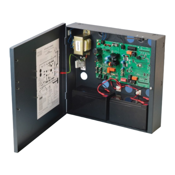
- Page 2 All manuals and user guides at all-guides.com ACTpro200 2 Door Station & Power Supply ____________________________________________________________________________________ AC AC E AC AC E 12V 0V 12V 0V 12V 0V 12V 0V 12V 7AHr 12V 7AHr Features This product consists of a 2-door controller housed inside a metal cabinet, complete with a monitored power supply.
- Page 3 All manuals and user guides at all-guides.com Power Supply Specification The power supply is capable of supplying a maximum of 3 Amps. This should be sufficient to power the 2-Door Station pcb, up to 4 readers, 2 locks and provide charging current for the batteries.
- Page 4 All manuals and user guides at all-guides.com 100 + 80 + 80 + 400 + 400 = 1060mA. In the event of a power fail, Battery 1 will supply the pcb, readers and 1 lock. Battery 2 will supply the lock for doors 2. The current draw on battery 1 would be 100+80+80+400 = 660mA A fully charged 7Ahr battery for battery 1 would last 7/0.66 = 10.6 hours.
Need help?
Do you have a question about the ACTpro 200 and is the answer not in the manual?
Questions and answers