Table of Contents
Advertisement
Quick Links
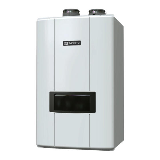
CONDENSING TANKLESS GAS WATER HEATER
Thank you for purchasing this Noritz Tankless Gas Water Heater.
Before using, please:
Read this guide completely for operation instructions.
Completely fill out the warranty registration card (included separately) and mail the detachable portion to Noritz
America Corporation. Keep this guide (and the remainder of the warranty registration card) where
it can be found whenever necessary.
Installation must conform with local codes, or in the absence of local codes, the National Fuel Gas Code, ANSI
Z223.1/NFPA 54- latest edition and/or CSA B149.1, Natural Gas and Propane Installation Code (NSCNGPIC).
Noritz America reserves the right to discontinue, or change at any time, the designs and/or specifications of its
products without notice.
WARNING
If the information in these instructions is not followed exactly, a fire or explosion may result,
causing property damage, personal injury, or death.
– Do not store or use gasoline or other inflammable vapors and liquids in the vicinity of this or any other
appliance.
– WHAT TO DO IF YOU SMELL GAS
• Do not try to light any appliance.
• Do not touch any electrical switch; do not use any phone in your building.
• Immediately call your gas supplier from a neighbor's phone. Follow the gas supplier's instructions.
• If you cannot reach your gas supplier, call the fire department.
– Installation and service must be performed by a qualified installer, service agency or the gas supplier.
Rev.07/19
Installation Manual
Models
NRCP111-DV / NRCP98-DV
• Natural Gas ( NG ) / Propane Gas ( LP )
c
Advertisement
Table of Contents

Subscribe to Our Youtube Channel
Related Manuals for Noritz NRCP98-DV


Summary of Contents for Noritz NRCP98-DV
- Page 1 CONDENSING TANKLESS GAS WATER HEATER Installation Manual Models NRCP111-DV / NRCP98-DV • Natural Gas ( NG ) / Propane Gas ( LP ) Thank you for purchasing this Noritz Tankless Gas Water Heater. Before using, please: Read this guide completely for operation instructions. Completely fill out the warranty registration card (included separately) and mail the detachable portion to Noritz America Corporation. Keep this guide (and the remainder of the warranty registration card) where it can be found whenever necessary. Installation must conform with local codes, or in the absence of local codes, the National Fuel Gas Code, ANSI Z223.1/NFPA 54- latest edition and/or CSA B149.1, Natural Gas and Propane Installation Code (NSCNGPIC). Noritz America reserves the right to discontinue, or change at any time, the designs and/or specifications of its products without notice. WARNING If the information in these instructions is not followed exactly, a fire or explosion may result, causing property damage, personal injury, or death. – Do not store or use gasoline or other inflammable vapors and liquids in the vicinity of this or any other appliance. – WHAT TO DO IF YOU SMELL GAS • Do not try to light any appliance.
- Page 2 Chapter 1 Product Accessories 1-1 Included Accessories 1-2 Optional Accessories Chapter 2 Product Specifications 2-1 Specifications 2-2 Dimensions & Connections Chapter 3 Safety Requirements 3-1 Safety Precautions 3-2 Before Installation 3-3 Choosing Installation Site 3-4 High Elevation Installations 3-5 Installation Clearance Chapter 4 Installation 4-1 Securing to the wall...
-
Page 3: Chapter 1. - Product Accessories
BRAND DATE 용 프리미엄 온수기(NRCP 2)_Spare parts kit label NORITZ 2018 . 12 . 24 COUNTRY BUYER CLIENT 공용 NORITZ DESIGNED BY CHEKED BY PAGE 추준영 김상훈 Chapter 1. – Product Accessories The following accessories are included with the box. Check for any missing 1-1. - Page 4 Chapter 1. – Product Accessories ■ On-Demand (Title 24) Kit (IHK-NRCP) Part Shape Part Shape Temperature Sensor Push Button (2 ties included) Switch Wire for Temperature Sensor Manual (4.0 ft [1.2 m]) ■ Outdoor Kit (VCK-NRCP-1) Part Shape Part Shape Hexagon Head Outdoor Vent Cap with Flange (w/Plate and Packing) Tapping Screw...
- Page 5 Chapter 1. – Product Accessories ■ Pipe Cover Kit (PC-9S) Part Shape Part Shape Frame Bracket 1 Front Cover Left Plate Frame Bracket 2 Dry Wall Anchor Right Plate Screws (M4x10L) Front Cover Bracket Knob Case Bracket Manual...
- Page 6 Specification may be changed without prior notice. The capacity may differ slightly, 2-1. Specifications depending on the water pressure, water supply, piping conditions, and water temperature. Model Name NRCP111-DV NRCP98-DV 199,000 Btu/h 180,000 Btu/h Gas Input Rate 18,000 Btu/h 18,000 Btu/h...
-
Page 7: Chapter 2. - Product Specifications
Chapter 2. – Product Specifications Dimensions & Connections 2-2. Dimensions & Connections 11.5" [292mm] 5.8" [148mm] 4.6" [117mm] Name of Component Exhaust Igniter Ignition Plug Burner High Limit Switch Primary Heat Exchanger Secondary Heat Exchanger On-Demand Terminal Block Control Panel Water Mixing Valve Recirculation Pump Hot Water Connection Condensate Trap Recirculation Return Connection with Filter... -
Page 8: Chapter 3. - Safety Requirements
Installation and Owner’s Guide before installation, operation and service the Water Heater. Noritz cannot anticipate every circumstance that might involve a potential hazard. Therefore, all possible incidents are not included in our warnings. Proper installation, operation, and service are your responsibility. -
Page 9: Before Installation
Before Installation Chapter 3. – Safety Requirements 3-2. Before Installation DANGER Check the fixing brackets and vent pipe yearly for damage or wear. Replace if necessary. WARNING Precautions on Vent Pipe Replacement The vent system will almost certainly need to be replaced when this appliance is being installed. Only use vent materials that are specified in this Installation Manual for use on this appliance. -
Page 10: Choosing Installation Site
Choosing Installation Site Chapter 3. – Safety Requirements 3-3. Choosing Installation Site Locate the appliance in an area where leakage from the unit or connections will not result in damage to the area adjacent to the appliance or to the lower floors of the structure. When such locations cannot be avoided, it is required that a suitable drain pan, adequately drained, be installed under the appliance. - Page 11 Choosing Installation Site Chapter 3. – Safety Requirements be installed as directed. Do not install the water heater where the exhaust will blow on outer walls or material not resistant to heat. Also consider the surrounding trees and animals. The heat and moisture from the water heater may cause discoloration of walls and resinous materials, or corrosion of aluminum materials.
-
Page 12: High Elevation Installations
3-4. High Elevation Installations •This unit is only ANSI/CSA certified for installation up to 4500 ft. (1,350 m) above sea level. •For installations at higher elevations, please refer to the directions below or contact Noritz America. Note: This water heater may be installed at elevation up to 10,000 ft for use with Natural Gas and Propane. The water heater must be set for a specific altitude using the Installer Mode Setting described below. -
Page 13: Outdoor Installation
Installation Clearances Chapter 3. – Safety Requirements Outdoor Installation Securing of space for repair/inspection Required Clearances From Heater In order to facilitate inspection and repair it is recommended Maintain the following clearance from both combustible to leave: and non-combustible materials. If possible, leave 8" (200mm) or more on either side of the unit to facilitate inspection. - Page 14 Installation Clearances Chapter 3. – Safety Requirements Clearance Requirements from Vent Terminations to Building Openings <When supplying combustion air from the outdoors (Direct Vent)> US Direct Vent Canadian Direct Vent Description Installations Installations Clearance above grade, veranda, porch, deck, or balcony 12 in (30 cm) 12 in (30 cm) Clearance to window or door that may be opened 12 in (30 cm)
-
Page 15: Chapter 4. - Installation
Securing to the wall Chapter 4. – Installation 4-1. Securing to the wall WARNING CLEARANCES FOR SERVICE ACCESS The water heater must be installed on a wall that can bear its weight. The Water heater can be installed on any suitable internal wall (suitable sound proofing may be required when installing onto a stud partition wall). -
Page 16: Vent Pipe Installation
Chapter 4. – Installation Vent Pipe Installation 4-2. Vent Pipe Installation (Indoor Installation Only) General Requirements • Under normal conditions, this appliance will not produce an exhaust flue temperature in excess of 149°F (65°C) and schedule 40 PVC pipe may be used as the vent material. •... -
Page 17: Maximum Vent Length
Chapter 4. – Installation Vent Pipe Installation Maximum Vent Length The unit can be adjusted to accommodate longer vent runs; refer to the below table to find the maximum vent length based on the number of elbows. Allowable Schedule 40 Vent Length (PVC, CPVC) Pipe diameter 3" (75mm) 2" (50mm) Max Equivalent Vent Length* No. - Page 18 AUTODESK � � � � � � � � � � Vent Pipe Installation Chapter 4. – Installation Vent Pipe Installation (DV-Direct Vent) Insert Vent Screen* in End of 90 Elbow Horizontal Vent Termination- PVC/CPVC Materials Only Hanger Exhaust • As illustrated on the right, make sure to keep a distance of 3' Straps (0.9m) or wider between the intake and exhaust when installing the vent piping.
- Page 19 Vent Pipe Installation Chapter 4. – Installation Vent Pipe Installation (DV-Direct Vent) Concentric PVC/CPVC Termination • The concentric termination may be shortened, but not lengthened from its original factory supplied length. • 2" (50mm) & 3" (75mm) PVC or CPVC pipe may be used with the concentric termination. Reducers will be needed to connect 2" pipe. Maintain the same vent pipe diameter from the water heater flue to the termination.
-
Page 20: Intake Exhaust
Vent Pipe Installation Chapter 4. – Installation Vent Pipe Installation (DV-Direct Vent) Horizontal Vent Termination- PVC/CPVC Materials Only * When 3' (0.9m) remote distance between Intake and Exhaust cannot be ensured. * Can not use Hood termination (PVT-HL) • Intake and exhaust should face the same Intake Exhaust 5.9"... - Page 21 AUTODESK � � � � � � � � � � Chapter 4. – Installation Vent Pipe Installation Vent Pipe Installation (SV-Non Direct Vent) When supplying combustion air from the indoors (SV-CK-3 Conversion Kit is required) Horizontal Vent Termination- PVC/CPVC Materials Only 3" Min Hanger •...
- Page 22 Vent Pipe Installation Chapter 4. – Installation Outdoor Installation Clearances (VCK-NRCP-1 Kit required) Note : Installation Clearances Recommended Service Minimum The outdoor enclosure for this appliance is from and Proper Operation Clearances approved for zero clearance to combustible Non-Combustibles Clearances construction. If the water heater is installed in Top of appliance 36 in (900mm) a narrow space or corner ensure that there is...
-
Page 23: Gas Piping
The installer must be professionally trained to do such work and must always follow all local and national codes and regulations. Gas line sizing calculations must be performed for every installation. Please contact Noritz America at 866-766-7489 if you have any questions or concerns. -
Page 24: Pressure Test
5" WC for NG or 8" WC for LP, the heater may continue to operate, but the other appliances in the house may experience flame loss or ignition failure, which can result in gas leakage into the home. Refer to the NFPA 54 for details. Please contact Noritz for details. For corrugated stainless steel tubing (CSST) capacity tables, please consult with the manufacturer. - Page 25 Gas Supply Piping Chapter 4. – Installation Gas Line Sizing for a Noritz Condensing Tankless Gas Water Heater Table 1. For Less than 8" WC initial supply pressure Maximum Natural Gas Delivery Capacity (0.5" WC Pressure Drop) Length (ft) Pipe size 10'(3m) 20'(6m)
-
Page 26: Water Piping
Water Piping Chapter 4. – Installation Installation must be performed by a qualified plumber. In the Commonwealth of Massachusetts, this 4-4. Water Piping product must be installed by a licensed plumber or gas fitter in accordance with the Massachusetts Plumbing and Fuel Gas Code 248 CMR Sections 2.00 and 5.00. Observe all applicable codes. This appliance is designed for domestic hot water applications only. -
Page 27: Drain Piping
If this water heater will be installed in an application where the supply water is hard, the water must be treated with either the Noritz H2Flow or Scale Shield or a water softener. Refer to the below tables for suggested treatment and maintenance measures to be taken based on the water hardness level. -
Page 28: Condensate Piping
Condensate Piping Chapter 4. – Installation 4-5. Condensate Piping CAUTION Due to the acidic nature of the condensate, be sure to properly drain and if necessary, treat the condensate prior to disposal. Damage caused by improperly handled condensate is not covered by the warranty. •... -
Page 29: Plumbing Applications
2. The water heater cannot be used for space heating applications. 3. Expansion tank is required if a backflow preventer is installed. 4. Noritz recommends the use of an Isolation valve kit with the installation. Cold Water Line Hot Water Line... - Page 30 Chapter 4. – Installation Plumbing Guidelines Recirculation Mode [ External Mode] · Provides most comfortable option. Maintains consistent hot water availability during specified times. · Timer can be manually customized or programmed to automatically learn daily usage patterns. · Ability to optimize by using Installer Mode function 3: RT to adjust loop temperature for maximum comfort and safety.
-
Page 31: Recirculation Mode
Chapter 4. – Installation Plumbing Guidelines / Pressure Relief Valve Recirculation Mode [ On Demand(tt24) Mode] · Provides best energy savings option · Designed to meet California Title 24 requirements. · Recirculation will only operate when the push button switch is pressed. Hot water will not be available immediately. - Page 32 Recirculation Mode [ Crossover(CrOS) Mode] · Provides recirculation option for homes without a dedicated return line by utilizing the cold water line as a return line. · Timer can be manually customized or programmed to automatically learn daily usage patterns. ·...
- Page 33 Pressure Relief Valve • External pressure relief valve must be installed. Observe the following. Failure to comply with the guidelines on installing the pressure relief valve and discharge piping can result in personal injury, death or substantial property damage. • DO NOT install a relief valve with pressure higher than 150psi. This is the maximum allowable relief valve setting for the water heater.
-
Page 34: Electrical Wiring
Electrical Wiring Chapter 4. – Installation Do not connect electrical power to the unit until all electrical wiring has 4-7. Electrical Wiring been completed. Do not connect electrical power to the unit until all electrical wiring has been completed. This appliance must be electrically grounded in accordance with local codes, or in the absence of local codes, with the National Electrical Code, ANSI/NFPA 70. -
Page 35: Setting The Control Panel
Setting the Control Panel Chapter 4. – Installation 4-8. Setting the Control Panel ►To use the ‘Recirculation Timer Mode’, the device’s internal clock should be adjusted to the current time. Clock settings can be set in the ‘User Mode’. [ To enter ‘User Mode’ ] [A:GA] is displayed on the display screen. - Page 36 Chapter 4. – Installation Setting the Control Panel Setting the Control Panel (Recirculation Setting) To set the recirculation mode (External, On-Demand, Crossover) 1. Press the 'Power Button' OFF. ('Display Screen' will be blank) 6. Press the 'Dial Button' to save the setting. 2. Press and hold the ‘Function Button’ for approximately 5 seconds to get into the ‘Installer Mode’.
- Page 37 Chapter 4. – Installation Setting the Control Panel Setting the Control Panel (High Elevation) To set the High Elevation Elevation above Sea Level 5:EL setting 0 ~ 1,999 ft (0 ~ 609 m) 0 - 2 (Default) 2,000 ~ 4,999 ft (610 ~ 1,523 m) 2 - 5 5,000 ~ 7,999 ft (1,524 ~ 2,438 m) 5 - 8...
-
Page 43: Quick Connect Multi System Installation
Chapter 4. – Installation Quick Connect 4-9. Quick Connect Multi System Installation The Quick Connect Multi System allows the installation of two units together utilizing only the Quick Connect Cord. ㆍQuick Connect Multi System cannot allows more than 2 units. ㆍAll units within Quick Connect Multi System must be of the same model. ㆍDifferent models cannot work as Quick Connect Multi System. - Page 44 Quick Connect Chapter 4. – Installation ※ All units must be set to the same settings listed below before using in the Quick Connect Multi System. 1. Set ‘on’ at [6:QC] in Installer Mode. (Refer to below) 2. Set Clock. (Refer to page 35 in the Installation Manual) 3.
- Page 45 When Noritz water heaters are installed in a Noritz Quick Connect Multi System, you can install a common venting system. Do not use common venting if the water heater is used within a Noritz Quick Connect Multi System with other manufacturer’s water heaters or other models. Include a condensate drain in the main trunk as illustrated in the following examples.
- Page 46 Common Vent Chapter 4. – Installation ● To determine the size of a common vent: Determine the total length (L) of the common vent, which consist of the horizontal width (W/W1) and vertical height (H/H1) Total Length (L) = W + H + W1 + H1 Require Load Total Length Total Btu/h...
-
Page 47: Pump Performance
Trial Operation Chapter 4. – Installation 4-11. Pump Trial Operation The installer should test operate the unit, explain to the customer how to use the unit, and give the owner this manual before leaving the installation. ● Before initiating a pump check, open a hot water fixture to confirm water is available to prevent damaging the pump. AUTODESK �... -
Page 48: Chapter 5. - Installation Check
Maintenance Chapter 5. – Installation Check 5-1. Maintenance Periodically check the following to ensure proper operation of the water heater.. •The venting system must be examined periodically by a qualified service technician to check for any leaks or corrosion. • The burner flame must be checked periodically for a proper blue color and consistency. •... -
Page 49: Maintenance Report
Maintenance Report Chapter 5. – Installation Check MAINTENANCE REPORT CAUTION In unusually dirty or dusty conditions, care must be taken to keep water heater cabinet door in place at all times. Failure to do so VOIDS WARRANTY! WARNING Allowing the water heater to operate with a dirty combustion chamber will hurt operation. Failure to clean the heat exchanger as needed by the installation location could result in water heater failure, property damage, personal injury, or death. -
Page 50: Final Check List
Final check list Chapter 5. – Installation Check 5-2. Final Check List Final check : On the installation conditions. • Is the Water Heater securely mounted on the wall? • Is there space for a drain which is close to the Water Heater? • Is there any combustible material near the Water Heater and vent pipe? •... - Page 51 Memo...
- Page 52 Installation Manual NORITZ AMERICA CO. 11160 Grace Avenue Fountain Valley, CA 92708 Phone : 866 - 766 - 7489 Rev.07/19...
Need help?
Do you have a question about the NRCP98-DV and is the answer not in the manual?
Questions and answers