Table of Contents
Advertisement
Quick Links
Advertisement
Table of Contents

Related Manuals for Gigabyte GA-B150N Phoenix-WIFI


Summary of Contents for Gigabyte GA-B150N Phoenix-WIFI
- Page 1 GA-B150N Phoenix- WIFI User's Manual Rev. 1001 12ME-B150NPF-1001R For more product details, please visit GIGABYTE's website. To reduce the impacts on global warming, the packaging materials of this product are recyclable and reusable. GIGABYTE works with you to protect the environment.
- Page 2 Motherboard GA-B150N Phoenix-WIFI Motherboard GA-B150N Phoenix-WIFI Oct. 23, 2015 Oct. 23, 2015 Wireless Module Country Approvals: See the latest safety and regulatory documents at: http://www.gigabyte.com/products/product-page.aspx?pid=5639#ov...
- Page 3 The trademarks mentioned in this manual are legally registered to their respective owners. Disclaimer Information in this manual is protected by copyright laws and is the property of GIGABYTE. without prior notice. No part of this manual may be reproduced, copied, translated, transmitted, or published in any form or by any means without GIGABYTE's prior written permission.
-
Page 4: Table Of Contents
Table of Contents GA-B150N Phoenix-WIFI Motherboard Layout ...............5 Chapter 1 Hardware Installation ..................6 Installation Precautions ..................6 ..................7 Installing the CPU ..................10 Installing the Memory ..................10 Installing an Expansion Card ................. 11 Back Panel Connectors .................. 11 Internal Connectors .................. -
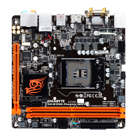
Page 5: Ga-B150N Phoenix-Wifi Motherboard Layout
GA-B150N Phoenix-WIFI Motherboard Layout CPU_FAN SYS_FAN1 KB_MS_USB3 ATX_12V_2X4 LGA1151 WIFI Module ® ASMedia USB 3.1 Controller USB31 TYPEC Intel ® GbE LAN (Note) USB30_LAN SYS_FAN2 B_BIOS M_BIOS SPDIF_O Intel B150 ® AUDIO ® F_AUDIO Super I/O PCIEX16 CODEC Box Contents... -
Page 6: Chapter 1 Hardware Installation
Chapter 1 Hardware Installation Installation Precautions The motherboard contains numerous delicate electronic circuits and components which can become damaged as a result of electrostatic discharge (ESD). Prior to installation, carefully read the user's manual and follow these procedures: Prior to installation, make sure the chassis is suitable for the motherboard. Prior to installation, do not remove or break motherboard S/N (Serial Number) sticker or warranty sticker provided by your dealer. - Page 7 Support for DDR4 2133 MHz memory modules Support for ECC UDIMM 1Rx8/2Rx8 memory modules (operate in non-ECC mode) Support for non-ECC UDIMM 1Rx8/2Rx8/1Rx16 memory modules (Go to GIGABYTE's website for the latest supported memory speeds and memory modules.) Onboard Integrated Graphics Processor-Intel ®...
- Page 8 Chipset: 6 x USB 3.0/2.0 ports (4 ports on the back panel, 2 ports available through the internal USB header) 2 x USB 2.0/1.1 ports (available through the internal USB header) ® Chipset+ASMedia USB 3.1 Controller: 1 x USB Type-C ™...
- Page 9 Form Factor Mini-ITX Form Factor; 17.0cm x 17.0cm prior notice. Please visit GIGABYTE's website for support lists of CPU, memory modules, and SSDs. Please visit the Support\Utility List page on GIGABYTE's website to download the latest version of apps. - 9 -...
-
Page 10: Installing The Cpu
Make sure that the motherboard supports the memory. It is recommended that memory of the same capacity, brand, speed, and chips be used. (Go to GIGABYTE's website for the latest supported memory speeds and memory modules.) Always turn off the computer and unplug the power cord from the power outlet before installing the memory to prevent hardware damage. -
Page 11: Installing An Expansion Card
The two memory sockets are divided into two channels and each channel has one memory socket as following: Channel A: DDR4_1 Channel B: DDR4_2 Due to CPU limitations, read the following guidelines before installing the memory in Dual Channel mode. Dual Channel mode cannot be enabled if only one memory module is installed. - Page 12 If you want to install a Side Speaker, you need to retask either the Line in or Mic in jack to be Side Speaker out through the audio driver. Please visit GIGABYTE's website for more software information. device and then remove it from the motherboard.
-
Page 13: Internal Connectors
Internal Connectors ATX_12V_2X4 F_AUDIO CPU_FAN SPDIF_O SYS_FAN1/SYS_FAN2 F_USB30 SATA3 2/3/4/5 F_USB F_PANEL CLR_CMOS SPEAKER Read the following guidelines before connecting external devices: First make sure your devices are compliant with the connectors you wish to connect. Before installing the devices, be sure to turn off the devices and your computer. Unplug the power cord from the power outlet to prevent damage to the devices. - Page 14 1/2) ATX_12V_2X4/ATX (2x4 12V Power Connector and 2x12 Main Power Connector) With the use of the power connector, the power supply can supply enough stable power to all the components off and all devices are properly installed. The power connector possesses a foolproof design. Connect the power supply cable to the power connector in the correct orientation.
- Page 15 5) SATA3 2/3/4/5 (SATA 6Gb/s Connectors) The SATA connectors conform to SATA 6Gb/s standard and are compatible with SATA 3Gb/s and SATA 1.5Gb/s standard. Each SATA connector supports a single SATA device. Pin No. SATA3 SATA3 To enable hot-plugging for the SATA ports, refer to Chapter 2, "BIOS Setup," "Peripherals\SATA 6) M.2 (M.2 Socket 3 Connector) The M.2 connector supports M.2 SATA SSDs and M.2 PCIe SSDs.
- Page 16 7) F_PANEL (Front Panel Header) Connect the power switch, reset switch, and system status indicator on the chassis to this header according to the pin assignments below. Note the positive and negative pins before connecting the cables. RES+ Reset Switch Power Switch RES- PLED-...
- Page 17 10) F_AUDIO (Front Panel Audio Header) your chassis front panel audio module to this header. Make sure the wire assignments of the module connector match the pin assignments of the motherboard header. Incorrect connection between the module connector and the motherboard header will make the device unable to work or even damage it. For HD Front Panel Audio: For AC'97 Front Panel Audio: Pin No.
- Page 18 13) F_USB (USB 2.0/1.1 Header) optional USB bracket. For purchasing the optional USB bracket, please contact the local dealer. Pin No. Pin No. Power (5V) USB DY+ Power (5V) USB DX- USB DY- No Pin USB DX+ Do not plug the IEEE 1394 bracket (2x5-pin) cable into the USB 2.0/1.1 header. Prior to installing the USB bracket, be sure to turn off your computer and unplug the power cord from the power outlet to prevent damage to the USB bracket.
-
Page 19: Chapter 2 Bios Setup
To access the BIOS Setup program, press the <Delete> key during the POST when the power is turned on. To upgrade the BIOS, use either the GIGABYTE Q-Flash or @BIOS utility. Q-Flash allows the user to quickly and easily upgrade or back up BIOS without entering the operating system. - Page 20 M.I.T. This section provides information on the BIOS version, CPU base clock, CPU frequency, memory frequency, total memory size, CPU temperature and CPU voltage, etc. Whether the system will work stably with the overclock/overvoltage settings you made is dependent on your overall and reduce the useful life of these components.
- Page 21 Uncore Frequency Displays the current CPU Uncore frequency. CPU Flex Ratio Override Enables or disables the CPU Flex Ratio. The maximum CPU clock ratio will be based on the CPU Flex Ratio Settings value if CPU Clock Ratio is set to Auto. (Default: Disabled) CPU Flex Ratio Settings Allows you to set the CPU Flex Ratio.
- Page 22 Package C State Limit (Note 1) Allows you to specify the C-state limit for the processor. Auto setting. (Default: Auto) (Note 1) CPU Thermal Monitor Enables or disables Intel ® Thermal Monitor function, a CPU overheating protection function. When enabled, the CPU core frequency and voltage will be reduced when the CPU is overheated.
- Page 23 Memory Enhancement Settings Provides several memory performance enhancement settings: Normal (basic performance), Relax OC, Enhanced Stability, and Enhanced Performance. (Default: Normal) Memory Timing Mode Manual and Advanced Manual allows the Memory Multiplier Tweaker, Channel Interleaving, Rank Interleaving Advanced Manual. Displays the memory voltage. Memory Multiplier Tweaker Provides different levels of memory auto-tuning.
- Page 24 Internal VR Control This section provides VR voltage control options. PC Health Status Reset Case Open Status Disabled Keeps or clears the record of previous chassis intrusion status. (Default) Enabled Clears the record of previous chassis intrusion status and the Case Open show "No"...
- Page 25 2nd System Fan Speed Control (SYS_FAN2 Connector) Allows you to determine whether to enable the fan speed control function and adjust the fan speed. Normal Allows the fan to run at different speeds according to the system temperature. You can adjust the fan speed with System Information Viewer based on your system requirements.
-
Page 26: System Information
System Information This section provides information on your motherboard model and BIOS version. You can also select the default language used by the BIOS and manually set the system time. System Language Selects the default language used by the BIOS. System Date Sets the system date. -
Page 27: Bios Features
A password is required for booting the system and for entering the BIOS Setup program. (Default) Full Screen LOGO Show Allows you to determine whether to display the GIGABYTE Logo at system startup. Disabled skips the GIGABYTE Logo when the system starts up. (Default: Enabled) Fast Boot Enables or disables Fast Boot to shorten the OS boot process. - Page 28 SATA Support All Sata Devices All SATA devices are functional in the operating system and during the POST. (Default) Last Boot HDD Only Except for the previous boot drive, all SATA devices are disabled before the OS boot process completes. Fast Boot is set to Enabled or Ultra Fast.
- Page 29 Other PCI Device ROM Priority Allows you to select whether to enable the UEFI or Legacy option ROM for the PCI device controller other than the LAN, storage device, and graphics controllers. Disabled Disables option ROM. Legacy Only Enables legacy option ROM only. UEFI Only Enables UEFI option ROM only.
-
Page 30: Peripherals
Peripherals Intel Platform Trust Technology (PTT) ® Enables or disables Intel PTT Technology. (Default: Disabled) Initial Display Output graphics. Audio LED Enables or disables the onboard audio LED function. Disables this function. Still Mode The LEDs stay constantly on. (Default) Beat Mode The brightness of the LED changes according to the music rhythm. - Page 31 Intel(R) Bios Guard Technology Enables or disables the Intel ® BIOS Guard feature, which protects the BIOS from malicious attacks. SATA Controller(s) Enables or disables the integrated SATA controllers. (Default: Enabled) SATA Mode Selection Serial ATA features such as Native Command Queuing and hot plug. (Default) Aggressive LPM Support Enables or disables the power saving feature, ALPM (Aggressive Link Power Management), for the Chipset SATA controllers.
-
Page 32: Chipset
Chipset VT-d (Note) ® Enables or disables Intel Virtualization Technology for Directed I/O. (Default: Disabled) Internal Graphics Enables or disables the onboard graphics function. (Default: Auto) DVMT Pre-Allocated Allows you to set the onboard graphics memory size. Options are: 32M~512M. (Default: 64M) DVMT Total Gfx Mem Allows you to allocate the DVMT memory size of the onboard graphics. -
Page 33: Power Management
Power Management AC BACK Determines the state of the system after the return of power from an AC power loss. Always Off The system stays off upon the return of the AC power. (Default) Always On The system is turned on upon the return of the AC power. Memory The system returns to its last known awake state upon the return of the AC power. - Page 34 Soft-Off by PWR-BTTN Instant-Off Press the power button and then the system will be turned off instantly. (Default) Delay 4 Sec. Press and hold the power button for 4 seconds to turn off the system. If the power button is pressed for less than 4 seconds, the system will enter suspend mode. Power Loading Enables or disables dummy load.
-
Page 35: Save & Exit
Save & Exit Save & Exit Setup Press <Enter> on this item and select Yes. This saves the changes to the CMOS and exits the BIOS Setup program. Select No or press <Esc> to return to the BIOS Setup Main Menu. Exit Without Saving Press <Enter>... -
Page 36: Chapter 3 Appendix
You can click the Xpress Install button and "Xpress Install" will install all of the selected drivers. Or click the arrow icon to individually install the drivers you need. Please visit GIGABYTE's website for more software information. - 36 -... -
Page 37: Regulatory Statements
Contravention will be prosecuted. We believe that the information contained herein was accurate in all respects at the time of printing. GIGABYTE cannot, however, assume any responsibility for errors or omissions in this text. Also note that the information in this document is subject to change without notice and should not be construed as a commitment by GIGABYTE. - Page 38 FCC Notice (U.S.A. Only) Operation is subject to the following two conditions: (1) this device may not cause harmful interference, and (2) this device must accept any interference received, including interference that may cause undesired operation. WARNING: This equipment has been tested and found to comply with the limits for a Class B digital device, pursuant to Part 15 of the FCC Rules.
- Page 39 Canada-Industry Canada (IC): This device complies with Canadian RSS-210. This device complies with Industry Canada license-exempt RSS standard(s). Operation is subject to the following two conditions: (1) this device may not cause interference, and (2) this device must accept any interference, including interference that may cause undesired operation of the device.
- Page 40 European Community Directive R&TTE Directive Compliance Statement: This equipment complies with all the requirements and other relevant provisions of Directive 1999/5/EC of the European Parliament and the Council of March 9, 1999 on Radio Equipment and Telecommunication Terminal Equipment (R&TTE). Member States.
- Page 41 - 41 -...
- Page 42 - 42 -...
- Page 43 - 43 -...
-
Page 44: Contact Us
Contact Us GIGA-BYTE TECHNOLOGY CO., LTD. Address: No.6, Baoqiang Rd., Xindian Dist., New Taipei City 231, Taiwan TEL: +886-2-8912-4000, FAX: +886-2-8912-4005 Tech. and Non-Tech. Support (Sales/Marketing) : http://esupport.gigabyte.com WEB address (English): http://www.gigabyte.com WEB address (Chinese): http://www.gigabyte.tw GIGABYTE eSupport To submit a technical or non-technical (Sales/Marketing) question, please link to: http://esupport.gigabyte.com...
Need help?
Do you have a question about the GA-B150N Phoenix-WIFI and is the answer not in the manual?
Questions and answers