Table of Contents
Advertisement
Advertisement
Table of Contents

Related Manuals for Gigabyte GA-B250M-DS3H


Summary of Contents for Gigabyte GA-B250M-DS3H
- Page 1 GA-B250M-DS3H User's Manual Rev. 1001 For more product details, please visit GIGABYTE's website. To reduce the impacts on global warming, the packaging materials of this product are recyclable and reusable. GIGABYTE works with you to protect the environment.
- Page 2 The trademarks mentioned in this manual are legally registered to their respective owners. Disclaimer Information in this manual is protected by copyright laws and is the property of GIGABYTE. No part of this manual may be reproduced, copied, translated, transmitted, or published in any form or by any means without GIGABYTE's prior written permission.
-
Page 3: Table Of Contents
Table of Contents GA-B250M-DS3H Motherboard Layout ................4 Chapter 1 Hardware Installation ..................5 Installation Precautions ..................5 ..................6 Installing the CPU .................... 9 Installing the Memory ..................9 Installing an Expansion Card ................. 10 Back Panel Connectors .................. 10 Internal Connectors ..................12 Chapter 2 BIOS Setup ....................20... -
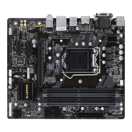
Page 4: Ga-B250M-Ds3H Motherboard Layout
GA-B250M-DS3H Motherboard Layout SYS_FAN CPU_FAN KB_MS_USB ATX_12V_2X4 LGA1151 R_USB30 USB30_LAN GA-B250M-DS3H AUDIO ® Realtek SATA3 1 0 GbE LAN PCIEX16 CODEC B_BIOS Intel B250 ® PCIEX1_1 SATA3 5 4 M_BIOS ® Super PCIEX1_2 F_AUDIO CLR_CMOS SPDIF_O F_USB2 F_USB1 F_PANEL Box Contents... -
Page 5: Chapter 1 Hardware Installation
Chapter 1 Hardware Installation Installation Precautions The motherboard contains numerous delicate electronic circuits and components which can become damaged as a result of electrostatic discharge (ESD). Prior to installation, carefully read the user's manual and follow these procedures: Prior to installation, make sure the chassis is suitable for the motherboard. Prior to installation, do not remove or break motherboard S/N (Serial Number) sticker or warranty sticker provided by your dealer. - Page 6 Support for non-ECC Un-buffered DIMM 1Rx8/2Rx8/1Rx16 memory modules * To support 2400 MHz or XMP memory, you must install a 7th generation processor. (Go to GIGABYTE's website for the latest supported memory speeds and memory modules.) Onboard Integrated Graphics Processor-Intel ®...
- Page 7 Chipset: 6 x USB 3.1 Gen 1 ports (4 ports on the back panel, 2 ports available through the internal USB header) 6 x USB 2.0/1.1 ports (2 ports on the back panel, 4 ports available through the internal USB headers) Internal 1 x 24-pin ATX main power connector Connectors...
- Page 8 Form Factor Micro ATX Form Factor; 22.6cm x 19.3cm prior notice. Please visit GIGABYTE's website for support lists of CPU, memory modules, SSDs, and M.2 devices. Please visit the Support\Utility List page on GIGABYTE's website to download the latest version of apps.
-
Page 9: Installing The Cpu
Make sure that the motherboard supports the memory. It is recommended that memory of the same capacity, brand, speed, and chips be used. (Go to GIGABYTE's website for the latest supported memory speeds and memory modules.) Always turn off the computer and unplug the power cord from the power outlet before installing the memory to prevent hardware damage. -
Page 10: Installing An Expansion Card
The four memory sockets are divided into two channels and each channel has two memory sockets as following: Channel A: DDR4_2, DDR4_4 Channel B: DDR4_1, DDR4_3 DDR4_4 DDR4_2 DDR4_3 DDR4_1 2 Modules DS/SS DS/SS DS/SS DS/SS 4 Modules DS/SS DS/SS DS/SS DS/SS (SS=Single-Sided, DS=Double-Sided, "- -"=No Memory) - Page 11 The line out jack. Use this audio jack for a headphone or 2-channel speaker. This jack can be used to Mic In (Pink) The Mic in jack. multi-channel audio feature through the audio driver. Please visit GIGABYTE's website for more software information. device and then remove it from the motherboard.
-
Page 12: Internal Connectors
Internal Connectors ATX_12V_2X4 SPDIF_O F_USB30 CPU_FAN F_USB1/F_USB2 SYS_FAN SATA3 0/1/2/3/4/5 M2Q_32G F_PANEL F_AUDIO CLR_CMOS Read the following guidelines before connecting external devices: First make sure your devices are compliant with the connectors you wish to connect. Before installing the devices, be sure to turn off the devices and your computer. Unplug the power cord from the power outlet to prevent damage to the devices. - Page 13 1/2) ATX_12V_2X4/ATX (2x4 12V Power Connector and 2x12 Main Power Connector) With the use of the power connector, the power supply can supply enough stable power to all the components off and all devices are properly installed. The power connector possesses a foolproof design. Connect the power supply cable to the power connector in the correct orientation.
- Page 14 3/4) CPU_FAN/SYS_FAN (Fan Headers) All fan headers on this motherboard are 4-pin. Most fan headers possess a foolproof insertion design. When connecting a fan cable, be sure to connect it in the correct orientation (the black connector wire is the ground wire). The speed control function requires the use of a fan with fan speed control design. For optimum heat dissipation, it is recommended that a system fan be installed inside the chassis.
- Page 15 6) M2Q_32G (M.2 Socket 3 Connector) The M.2 connector supports M.2 SATA SSDs and M.2 PCIe SSDs. Follow the steps below to correctly install an M.2 SSD in the M.2 connector. Step 1: Use a screw driver to unfasten the screw and nut from the motherboard. Locate the proper mounting hole Step 2: Slide the M.2 SSD into the connector at an angle.
- Page 16 7) F_PANEL (Front Panel Header) Connect the power switch, reset switch, speaker, chassis intrusion switch/sensor and system status indicator on the chassis to this header according to the pin assignments below. Note the positive and negative pins before connecting the cables. PLED/PWR_LED (Power LED): Power LED Power Switch...
- Page 17 9) SPDIF_O (S/PDIF Out Header) This header supports digital S/PDIF Out and connects a S/PDIF digital audio cable (provided by expansion cards) for digital audio output from your motherboard to certain expansion cards like graphics cards and sound cards. For example, some graphics cards may require you to use a S/PDIF digital audio cable for digital audio output from your motherboard to your graphics card if you wish to connect an HDMI display to the graphics card and have digital audio output from the HDMI display at the same time.
- Page 18 12) COM (Serial Port Header) The COM header can provide one serial port via an optional COM port cable. For purchasing the optional COM port cable, please contact the local dealer. Pin No. Pin No. NDCD- NDSR- NSIN NRTS- NSOUT NCTS- NDTR- NRI-...
- Page 19 15) BAT (Battery) in the CMOS when the computer is turned off. Replace the battery when the battery voltage drops to a low level, or the CMOS values may not be accurate or may be lost. You may clear the CMOS values by removing the battery: 1.
-
Page 20: Chapter 2 Bios Setup
To access the BIOS Setup program, press the <Delete> key during the POST when the power is turned on. To upgrade the BIOS, use either the GIGABYTE Q-Flash or @BIOS utility. Q-Flash allows the user to quickly and easily upgrade or back up BIOS without entering the operating system. - Page 21 M.I.T. Whether the system will work stably with the overclock/overvoltage settings you made is dependent on your overall and reduce the useful life of these components. This page is for advanced users only and we recommend you not to alter the default settings to prevent system instability or other unexpected results. (Inadequately altering the settings may result in system's failure to boot.
- Page 22 AVX Offset (Note) AVX offset is the negative offset of AVX ratio. Uncore Ratio Allows you to set the CPU Uncore ratio. The adjustable range is dependent on the CPU being used. Uncore Frequency Displays the current CPU Uncore frequency. CPU Flex Ratio Override Enables or disables the CPU Flex Ratio.
- Page 23 C6/C7 State Support (Note 1) Allows you to determine whether to let the CPU enter C6/C7 mode in system halt state. When enabled, the CPU core frequency and voltage will be reduced during system halt state to decrease power consumption. The C6/C7 state is a more enhanced power-saving state than C3.
- Page 24 Memory Odd Ratio(100/133 or 200/266) Allows you to manually adjust the memory reference clock. (Default: Auto) Memory Frequency (MHz) is the memory frequency that is automatically adjusted according to the System Memory Multiplier settings. Advanced Memory Settings (Note) , System Memory Multiplier, Memory Odd Ratio(100/133 or 200/266), Memory Frequency(Mhz) The settings above are synchronous to those under the same items on the Advanced Frequency Settings menu.
- Page 25 Channel A/B Memory Sub Timings This sub-menu provides memory timing settings for each channel of memory. The respective timing setting Memory Timing Mode is set to Manual or Advanced Manual. Note: Your system may become unstable or fail to boot after you make changes on the memory timings. If this occurs, please reset the board to default values by loading optimized defaults or clearing the CMOS values.
- Page 26 Smart Fan 5 Settings Monitor Allows you to select a target to monitor and to make further adjustment. (Default: CPU FAN) Fan Speed Control Allows you to determine whether to enable the fan speed control function and adjust the fan speed. Normal Allows the fan to run at different speeds according to the temperature.
-
Page 27: System
System This section provides information on your motherboard model and BIOS version. You can also select the default language used by the BIOS and manually set the system time. Access Level Displays the current access level depending on the type of password protection used. (If no password is set, the default will display as Administrator.) The Administrator level allows you to make changes to all BIOS settings;... -
Page 28: Bios
A password is required for booting the system and for entering the BIOS Setup program. (Default) Full Screen LOGO Show Allows you to determine whether to display the GIGABYTE Logo at system startup. Disabled skips the GIGABYTE Logo when the system starts up. (Default: Enabled) Boot Option Priorities... - Page 29 Fast Boot Enables or disables Fast Boot to shorten the OS boot process. Ultra Fast provides the fastest bootup speed. (Default: Disabled) SATA Support All Sata Devices All SATA devices are functional in the operating system and during the POST. (Default) Last Boot HDD Only Except for the previous boot drive, all SATA devices are disabled before the OS boot process completes.
- Page 30 LAN PXE Boot Option ROM Allows you to select whether to enable the legacy option ROM for the LAN controller. (Default: Disabled) CSM Support is set to Enabled. Storage Boot Option Control Allows you to select whether to enable the UEFI or legacy option ROM for the storage device controller. Do not launch Disables option ROM.
-
Page 31: Peripherals
Peripherals Initial Display Output graphics. OnBoard LAN Controller Enables or disables the onboard LAN function. If you wish to install a 3rd party add-in network card instead of using the onboard LAN, set this item to Disabled. Ambient LED Enables or disables the onboard audio LED. (Default: On) Intel Platform Trust Technology (PTT) Enables or disables Intel ®... - Page 32 Intel(R) Bios Guard Technology Enables or disables the Intel ® BIOS Guard feature, which protects the BIOS from malicious attacks. Network Stack Disables or enables booting from the network to install a GPT format OS, such as installing the OS from the Windows Deployment Services server.
- Page 33 SATA Controller(s) Enables or disables the integrated SATA controllers. (Default: Enabled) SATA Mode Selection Intel RST With Intel Optane System Acceleration Enables Intel ® Optane ™ Technology support for the SATA controllers. Serial ATA features such as Native Command Queuing and hot plug. (Default) Aggressive LPM Support Enables or disables the power saving feature, ALPM (Aggressive Link Power Management), for the Chipset SATA controllers.
-
Page 34: Chipset
Chipset (Note) VT-d Enables or disables Intel ® Virtualization Technology for Directed I/O. (Default: Enabled) Internal Graphics Enables or disables the onboard graphics function. (Default: Auto) DVMT Pre-Allocated Allows you to set the onboard graphics memory size. Options are: 32M~1024M. (Default: 32M) DVMT Total Gfx Mem Allows you to allocate the DVMT memory size of the onboard graphics. -
Page 35: Power
Power Platform Power Management Enables or disables the Active State Power Management function (ASPM). (Default: Disabled) PEG ASPM Platform Power Management is set to Enabled. (Default: Enabled) PCH ASPM Platform Power Management is set to Enabled. (Default: Enabled) DMI ASPM Platform Power Management is set to Enabled. - Page 36 Power On Password Set the password when Power On By Keyboard is set to Password. Press <Enter> on this item and set a password with up to 5 characters and then press <Enter> to accept. To turn on the system, enter the password and press <Enter>. Note: To cancel the password, press <Enter>...
-
Page 37: Save & Exit
Save & Exit Save & Exit Setup Press <Enter> on this item and select Yes. This saves the changes to the CMOS and exits the BIOS Setup program. Select No or press <Esc> to return to the BIOS Setup Main Menu. Exit Without Saving Press <Enter>... -
Page 38: Chapter 3 Appendix
You can click the Xpress Install button and "Xpress Install" will install all of the selected drivers. Or click the arrow icon to individually install the drivers you need. Please visit GIGABYTE's website for more software information. - 38 -... -
Page 39: Regulatory Statements
Contravention will be prosecuted. We believe that the information contained herein was accurate in all respects at the time of printing. GIGABYTE cannot, however, assume any responsibility for errors or omissions in this text. Also note that the information in this document is subject to change without notice and should not be construed as a commitment by GIGABYTE. - Page 40 FCC Notice (U.S.A. Only) This equipment has been tested and found to comply with the limits for a Class B digital device, pursuant to Part 15 of the FCC Rules. These limits are designed to provide reasonable protection against harmful interference in a residential installation.
-
Page 41: Contact Us
Contact Us GIGA-BYTE TECHNOLOGY CO., LTD. Address: No.6, Baoqiang Rd., Xindian Dist., New Taipei City 231, Taiwan TEL: +886-2-8912-4000, FAX: +886-2-8912-4005 Tech. and Non-Tech. Support (Sales/Marketing) : http://esupport.gigabyte.com WEB address (English): http://www.gigabyte.com WEB address (Chinese): http://www.gigabyte.tw GIGABYTE eSupport To submit a technical or non-technical (Sales/Marketing) question, please link to: http://esupport.gigabyte.com...
Need help?
Do you have a question about the GA-B250M-DS3H and is the answer not in the manual?
Questions and answers