Table of Contents
Advertisement
Quick Links
Advertisement
Table of Contents

Related Manuals for GIGA-BYTE TECHNOLOGY MZ72-HB2


Summary of Contents for GIGA-BYTE TECHNOLOGY MZ72-HB2
- Page 1 MZ72-HB2 AMD EPYC™ 7003 Dual Sockets Server Motherboard User Manual Rev. 3.0...
- Page 2 Copyright © 2022 GIGA-BYTE TECHNOLOGY CO., LTD. All rights reserved. The trademarks mentioned in this manual are legally registered to their respective owners. Disclaimer Information in this manual is protected by copyright laws and is the property of GIGABYTE. Changes to the specifications and features in this manual may be made by GIGABYTE without prior notice.
-
Page 3: Table Of Contents
Table of Contents MZ72-HB2 Motherboard Layout ..................5 Block Diagram .........................7 Chapter 1 Hardware Installation ..................8 Installation Precautions ..................8 1-2 Product Specifications ..................9 Installing and Removing the CPU and Heat Sink ........... 12 Installing and Removing Memory ..............13 1-4-1 8-Channel Memory Configuration ................13 1-4-2 Installing and Removing the Memory Module ............14... - Page 4 2-2-19 MAC IPv4 Network Configuration ................64 2-2-20 MAC IPv6 Network Configuration ................65 AMD CBS Menu ..................... 66 2-3-1 CPU Common Options ...................67 2-3-2 DF Common Options ....................73 2-3-3 UMC Common Options ..................78 2-3-4 NBIO Common Options ..................93 2-3-5 FCH Common Options ...................99 2-3-6 SOC Miscellaneous Control .................103 2-3-7 Workload Tuning ....................104 AMD PBS Menu ...................
-
Page 5: Mz72-Hb2 Motherboard Layout
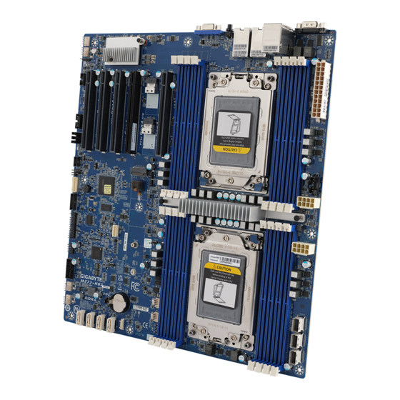
MZ72-HB2 Motherboard Layout 34 35 36 37 CPU0 CPU1 - 5 -... - Page 6 Item Code Description VGA Port SW_ID ID Button with LED LAN1 10GbE LAN Port #1 LAN2 10GbE LAN Port #2 USB3_MLAN Server Management LAN Port (Top)/ USB3.0 Ports (Bottom) COM1 Serial Port 2 x 12 Pin Main Power Connector PMBUS PMBus Connector P12V_1 2 x 4 Pin 12V Power Connector (for CPU0)
-
Page 7: Block Diagram
Block Diagram - 7 -... -
Page 8: Chapter 1 Hardware Installation
Chapter 1 Hardware Installation Installation Precautions The motherboard contains numerous delicate electronic circuits and components which can become damaged as a result of electrostatic discharge (ESD). Prior to installation, carefully read the user's manual and follow these procedures: • Prior to installation, do not remove or break motherboard S/N (Serial Number) sticker or warranty sticker provided by your dealer. -
Page 9: Product Specifications
Product Specifications NOTE: We reserve the right to make any changes to the product specifications and product-related information without prior notice. E-ATX Š Form Factor 305W x 330D (mm) Š AMD EPYC™ 7003 processors with AMD 3D V-Cache™ Technology Socket Security Š... - Page 10 Expansion Slots Š Slot_6: 1 x PCIe x16 (Gen4 x16 bus) slot ( from CPU_0) Slot_4: 1 x PCIe x16 (Gen4 x16 bus) slot ( from CPU_0) Š Slot_3: 1 x PCIe x16 (Gen4 x16 bus) slot ( from CPU_1) Š...
- Page 11 Board Aspeed® AST2600 management controller Š Management GIGABYTE Management Console (AMI MegaRAC SP-X) web interface Š Dashboard Š HTML5 KVM Š Security Sensor Monitor (Voltage, RPM, Temperature, CPU Status …etc.) Š Sensor Reading History Data Š FRU Information Š SEL Log in Linear Storage / Circular Storage Policy Š...
-
Page 12: Installing And Removing The Cpu And Heat Sink
Installing and Removing the CPU and Heat Sink Read the following guidelines before you begin to install the CPU: • Make sure that the motherboard supports the CPU. • Always turn off the computer and unplug the power cord from the power outlet before installing the CPU to prevent hardware damage. -
Page 13: Installing And Removing Memory
Installing and Removing Memory Read the following guidelines before you begin to install the memory: • Make sure that the motherboard supports the memory. It is recommended that memory of the same capacity, brand, speed, and chips be used. • Always turn off the computer and unplug the power cord from the power outlet before installing the memory to prevent hardware damage. -
Page 14: Installing And Removing The Memory Module
1-4-2 Installing and Removing the Memory Module Before installing a memory module, make sure to turn off the computer and unplug the power cord from the power outlet to prevent damage to the memory module. Be sure to install DDR4 DIMMs on to this motherboard. Follow these instructions to install a DIMM module: Insert the DIMM memory module vertically into the DIMM slot and push it down. -
Page 15: Memory Population Table
1-4-4 Memory Population Table EPYC Memory Speed based on DIMM Population (One DIMM per Channel) DIMM Population DIMM Max EPYC 7003 Type DDR Frequency (MHz) DIMM 0 1R (1 Rank) 3200 RDIMM 2R or 2DR (2 Ranks) 3200 4DR (4 Ranks) 3200 LRDIMM 2S2R (4 Ranks) -
Page 16: Installing And Removing The M.2 Ssd Module
Installing and Removing the M.2 SSD Module Follow the steps below to install an optional M.2 SSD module on your motherboard. Step1. Insert the M.2 SSD module into the slot. Step2. Secure it with the screw, tightening as necessary to fasten the M.2 SSD module in place. Hardware Installation - 16 -... -
Page 17: Back Panel Connectors
Back Panel Connectors Serial Port Connects to serial-based mouse or data processing devices. 10/100/1000 Server Management LAN Port The LAN port provides Internet connection with data transfer speeds of 10/100/1000Mbps. This port is the dedicated LAN port for Server Management. USB 3.0 Ports The USB port supports the USB 3.0 specification. -
Page 18: Internal Connectors
Internal Connectors CPU0 CPU1 F_USB2 P12V_1 (for CPU0) 12) FP_1 P12V_2 (for CPU1) 13) BP_1 SATA0/SATA1/SATA2/SATA3 14) SPI_TPM SATA_SGP 15) IPMB CPU0_FAN/ CPU1_FAN 16) CN_NSCI SYS_FAN1/SYS_FAN2 17) LED_BMC SYS_FAN3/SYS_FAN4 18) BAT PMBUS 19) CASE_OPEN 10) F_USB3 Read the following guidelines before connecting external devices: •... - Page 19 1/2/3) ATX/P12V_1/P12V_2 (2x12 Main Power Connector and 2x4 12V Power Connector) With the use of the power connector, the power supply can supply enough stable power to all the components on the motherboard. Before connecting the power connector, first make sure the power supply is turned off and all devices are properly installed. The power connector possesses a foolproof design. Connect the power supply cable to the power connector in the correct orientation.
- Page 20 4) SATA0/SATA1/SATA2/SATA3 (SATA 6Gb/s Connectors) The SATA connectors conform to SATA 6Gb/s standard and are compatible with SATA 3Gb/s standard. Each SATA connector supports a single SATA device. Pin No. Definition 5) SATA_SGP (SATA SGPIO) Connector Serial General Purpose Input/Output (SGPIO) is a communication method used between a host bus adapter (HBA) and a main board.
- Page 21 6/7/8) CPU0_FAN//CPU1_FAN/SYS_FAN1/SYS_FAN2/SYS_FAN3/SYS_FAN4 (CPU FAN/System FAN Headers) The motherboard has two 4-pin CPU fan header (CPU_FAN), and four 4-pin (SYS_FAN) system fan headers. Most fan headers possess a foolproof insertion design. When connecting a fan cable, be sure to connect it in the correct orientation (the black connector wire is the ground wire). The motherboard supports CPU fan speed control, which requires the use of a CPU fan with fan speed control design.
- Page 22 9) PMBus Connector The Power Management Bus (PMBus) is a variant of the System Management Bus (SMBus) which is targeted at digital management of power supplies. Pin No. Definition PMBus Clock PMBus Data PMBus Alert 3.3V Sense 10/11) F_USB3/ F_USB2 (USB 3.0 Connector/ 2.0 Header) The connector/header conform to USB 2.0/ 3.0 specification. Each USB connector/header can provide two USB ports via an optional USB bracket.
- Page 23 12) FP_1 (Front Panel Header) Connect the power switch, reset switch, speaker, chassis intrusion switch/sensor and system status indicator on the chassis to this header according to the pin assignments below. Note the positive and negative pins before connecting the cables. Pin No.
- Page 24 14) SPI_TPM (Trusted Platform Module Connector) Trusted Platform Module (TPM) is an international standard for a secure cryptoprocessor, a dedicated microcontroller designed to secure hardware through integrated cryptographic keys. 13 14 Pin No. Definition Pin No. Definition Clock No Connect P_3V3_AUX LPC_LAD2 LPC_RST...
- Page 25 16) CN_NCSI (NCSI Connector) Pin No. Definition Pin No. Definition NCSI_CLK NCSI_RX_D0 NCSI_RX_D1 NCSI_CRS_DV NCSI_RX_ER P3V3_AUX NCSI_TX_D1 NCSI_TX_D0 NCSI_TX_EN NCSI_PRESENT P3V3_AUX 17) LED_BMC (BMC Firmware Readiness LED) State Description BMC firmware is initial Blink BMC firmware is ready AC loss Hardware Installation - 25 -...
- Page 26 18) BAT (Battery Socket) The battery provides power to keep the values (such as BIOS configurations, date, and time information) in the CMOS when the computer is turned off. Replace the battery when the battery voltage drops to a low level, or the CMOS values may not be accurate or may be lost. • Always turn off your computer and unplug the power cord before replacing the battery. •...
-
Page 27: Jumper Settings
Jumper Settings NCSI_SW LAN1 CN_NCSI Clear CMOS CLR_CMOS Default Enable Jumper Name Jumper Setting 1-2: Normal operation. (Default) Clear CMOS 2-3: Clear CMOS data. HSMB_SEL BIOS Defined BIOS Defined BIOS PWD Clear Supervisor Password Normal [Default] BIOS Recovery BIOS Recovery Mode Normal [Default] Hardware Installation - 27 -... -
Page 28: Chapter 2 Bios Setup
Chapter 2 BIOS Setup BIOS (Basic Input and Output System) records hardware parameters of the system in the EFI on the motherboard. Its major functions include conducting the Power-On Self-Test (POST) during system startup, saving system parameters, loading the operating system etc. The BIOS includes a BIOS Setup program that allows the user to modify basic system configuration settings or to activate certain system features. When the power is turned off, the battery on the motherboard supplies the necessary power to the CMOS to keep the configuration values in the CMOS. - Page 29 Main This setup page includes all the items of the standard compatible BIOS. Advanced This setup page includes all the items of AMI BIOS special enhanced features. (ex: Auto detect fan and temperature status, automatically configure hard disk parameters.) AMD CBS This setup page includes the common items for configuration of AMD motherboard-related information. AMD PBS Option This setup page includes the common items for configuration of AMD CPM RAS related settings. Chipset This setup page includes all the submenu options for configuring the functions of the North Bridge.
-
Page 30: The Main Menu
The Main Menu Once you enter the BIOS Setup program, the Main Menu (as shown below) appears on the screen. Use arrow keys to move among the items and press <Enter> to accept or enter other sub-menu. Main Menu Help The on-screen description of a highlighted setup option is displayed on the bottom line of the Main Menu. - Page 31 Parameter Description BIOS Information Project Name Displays the project name information. Project Version Displays version number of the BIOS setup utility. Build Date and Time Displays the date and time when the BIOS setup utility was created. BMC Information (Note1) BMC Firmware Version Displays BMC firmware version information. (Note1) Processor Information CPU# Brand String/ CPU Speed/ Displays the technical specifications for the installed processor(s).
- Page 32 Parameter Description AGESA PI Version PI Version Displays AGESA PI version information. Onboard LAN Information LAN1 MAC Address Displays LAN MAC address information. (Note3) LAN2 MAC Address (Note3) Displays LAN MAC address information. System Date Sets the date following the weekday-month-day-year format. System Time Sets the system time following the hour-minute-second format.
-
Page 33: Advanced Menu
Advanced Menu The Advanced Menu displays submenu options for configuring the function of various hardware components. Select a submenu item, then press <Enter> to access the related submenu screen. When Boot Mode Select is set to UEFI (Default) BIOS Setup - 33 -... - Page 34 When "Boot Mode Select" is set to Legacy in the Boot > Boot Mode Select section BIOS Setup - 34 -...
-
Page 35: Trusted Computing
2-2-1 Trusted Computing Parameter Description Configuration Enable/Disable BIOS support for security device. OS will not show security device. TCG EFI protocol and INT1A interface will not be Security Device Support available. Options available: Enable, Disable. Default setting is Enable. Select Enable to activate TPM support feature. SPI TPM Support Options available: Enabled, Disabled. -
Page 36: Psp Firmware Versions
2-2-2 PSP Firmware Versions The PSP Firmware Versions page displays the basic PSP firmware version information. Items on this window are non-configurable. BIOS Setup - 36 -... -
Page 37: Legacy Video Select
2-2-3 Legacy Video Select Description Parameter Selects between onboard or external VGA support. OnBrd/Ext VGA Select Options available: Auto, Onboard, External. Default setting is Onboard. BIOS Setup - 37 -... -
Page 38: Ast2600 Super Io Configuration
2-2-4 AST2600 Super IO Configuration Description Parameter AST2600 Super IO Configuration Super IO Chip Displays the super IO chip information Serial Port 1 Configuration Press [Enter] for configuration of advanced items. BIOS Setup - 38 -... - Page 39 2-2-4-1 Serial Port 1 Configuration Description Parameter Serial Port 1 Configuration Enable/Disable the Serial Port (COM). When set to Enabled allows you to configure the Serial port 1 settings. When set to Disabled, displays no Serial Port (Note1) configuration for the serial port. Options available: Enabled, Disabled. Default setting is Enabled. Devices Settings Displays the Serial Port 1 device settings. (Note2) Select an optimal settings for Super IO Device.
-
Page 40: S5 Rtc Wake Settings
2-2-5 S5 RTC Wake Settings Parameter Description Enable/Disable system wake on alarm event. Options available: Disabled, Fixed Time. When Fixed Time is selected, Wake System from S5 system will wake on the hr::min::sec specified. Default setting is Disabled. BIOS Setup - 40 -... -
Page 41: Serial Port Console Redirection
2-2-6 Serial Port Console Redirection Parameter Description Select whether to enable console redirection for specified device. Console COM1/Serial Over LAN redirection enables the users to manage the system from a remote Console Redirection location. (Note) Options available: Enabled, Disabled. Default setting is Disabled. Press [Enter] to configure advanced items. Please note that this item is configurable when COM1/Serial Over LAN Console Redirection is set to Enabled. - Page 42 Parameter Description Parity Š – A parity bit can be sent with the data bits to detect some transmission errors. – Even: parity bit is 0 if the num of 1's in the data bits is even. – Odd: parity bit is 0 if num of 1's in the data bits is odd. –...
- Page 43 Parameter Description Legacy Console Redirection Press [Enter] to configure advanced items. Redirection COM Port Š – Selects a COM port for Legacy serial redirection. – Default setting is COM1/SOL. Resolution Š – Selects the number of rows and columns used in Console Redirection for legacy OS support. Legacy Console Redirection –...
- Page 44 Parameter Description Flow Control Š – Flow control can prevent data loss from buffer overflow. When sending data, if the receiving buffers are full, a 'stop' signal can Serial Port for Out-of-Band be sent to stop the data flow. Once the buffers are empty, a 'start' EMS Console Redirection signal can be sent to re-start the flow. Hardware flow control uses Settings(continued) two wires to send start/stop signals. – Options available: None, Hardware RTS/CTS, Software Xon/Xoff. Default setting is None.
-
Page 45: Cpu Configuration
2-2-7 CPU Configuration Description Parameter Enable/Disable the CPU Virtualization. SVM Mode Options available: Enabled, Disabled. Default setting is Enabled. Press [Enter] to view the memory information related to CPU 0/1. CPU 0/1 Information BIOS Setup - 45 -... -
Page 46: Pci Subsystem Settings
2-2-8 PCI Subsystem Settings BIOS Setup - 46 -... - Page 47 Description Parameter Displays the PCI Bus Driver version information. PCI Bus Driver Version Change the PCIe lanes. PCIE_# Lanes Options available: Disabled, Auto, x8, x4x4, x16, x8x8, x8x4x4, (Note1) x4x4x8, x4x4x4x4. Default setting is Auto. When enabled, this setting will initialize the device expansion ROM PCIE_ # I/O ROM for the related PCI-E slot.
-
Page 48: Usb Configuration
2-2-9 USB Configuration Parameter Description USB Configuration USB Module Version Displays the USB module version information. USB Controllers Displays the supported USB controllers. USB Devices: Displays the USB devices connected to the system. Enable/Disable the Legacy USB support function. AUTO option disables legacy support if no USB devices are connected. - Page 49 Parameter Description USB hardware delays and time-outs Selects the time-out value for USB Control/Bulk/Interrupt transfers. USB transfer time-out Options available: 1 sec, 5 sec, 10 sec, 20 sec. Default setting is 20 sec. Selects the time-out value during a USB mass storage device reset.
-
Page 50: Network Stack Configuration
2-2-10 Network Stack Configuration Parameter Description Enable/Disable the UEFI network stack. Network Stack Options available: Enabled, Disabled. Default setting is Enabled. Enable/Disable the Ipv4 PXE feature. Ipv4 PXE Support (Note) Options available: Enabled, Disabled. Default setting is Enabled. Enable/Disable the Ipv4 HTTP feature. Ipv4 HTTP Support (Note) Options available: Enabled, Disabled. -
Page 51: Nvme Configuration
2-2-11 NVMe Configuration Parameter Description NVMe Configuration Displays the NVMe devices connected to the system. Enable/Disable NVMe LED Control. NVMe LED Control Options available: System Default, Disabled, Enabled. Default setting is System Default. BIOS Setup - 51 -... -
Page 52: Sata Configuration
2-2-12 SATA Configuration Parameter Description Displays the installed HDD devices information. System will automatically SATA Configuration detect HDD type. BIOS Setup - 52 -... -
Page 53: Graphic Output Configuration
2-2-13 Graphic Output Configuration Parameter Description Selects output device type. Output Device Type Options available: First loaded Device, Onboard Device, External Device, Specific Device. Default setting is Onboard Device. BIOS Setup - 53 -... -
Page 54: Amd Mem Configuration Status
2-2-14 AMD Mem Configuration Status Description Parameter Press [Enter] to view the memory configuration status related to CPU 0/1. CPU0/1 BIOS Setup - 54 -... -
Page 55: Tls Auth Configuration
2-2-15 Tls Auth Configuration Parameter Description Press [Enter] for configuration of advanced items. Enroll Cert Š – Press [Enter] to enroll a certificate • Enroll Cert Using File • Cert GUID Server CA Configuration Input digit character in 1111111-2222-3333-4444-1234567890ab format. – Commit Changes and Exit – Discard Changes and Exit Delete Cert Š Press [Enter] for configuration of advanced items. Client Cert Configuration BIOS Setup - 55 -... -
Page 56: Iscsi Configuration
2-2-16 iSCSI Configuration Parameter Description iSCSI Initiator Name Add an Attempt Press [Enter] to configure advanced items. Delete Attempts Press [Enter] to configure advanced items. Change Attempt Order Press [Enter] to configure advanced items. BIOS Setup - 56 -... -
Page 57: Broadcom Bcm57416 10Gbase-T Network Connection
2-2-17 Broadcom BCM57416 10GBASE-T Network Connection Parameter Description Press [Enter] to view firmware image information. Firmware Image Menu Press [Enter] to configure advanced items. Multi-Function Mode Š – Configures the NIC Hardware Mode. – Options available: SF, NPAR 1.0. Default setting is SF. Number of VFs Per PF Š – Configures the number of Virtual Functions Per Physical Function in multiples of 8 (1-128). This field is only applicable when SR-IOV is enabled. – Default setting is 8. SR-IOV Device Configuration Menu Š... - Page 58 Description Parameter Energy Efficient Ethernet Š – Enable/Disable Energy Efficient Ethernet operation. – Options available: Enabled, Disabled. Default setting is Enabled. Operational Link Speed Š – Configures the link speed setting to be used as the default link speed for the selected port. – Options available: AutoNeg. Default setting is AutoNeg. Support RDMA Š – Enable/Disable RDMA support for this port. –...
- Page 59 Parameter Description Setup Key Stroke Š – Configures key strokes to invoke the configuration menu. – Options available: Ctrl-S, Ctrl-B. Default setting is Ctrl-S. Banner Message Timeout Š – Selects the timeout value. (0 defaults to 4 seconds, 15 is no delay, 1-14 is timeout value in seconds) –...
- Page 60 2-2-17-1 iSCSI Boot Configuration Menu Parameter Description Press [Enter] to configure advanced items. TCP/IP Parameters via DHCP Š – Acquires TCP/IP Parameters via DHCP. – Options available: Enabled, Disabled. Default setting is Enabled. IP Autoconfiguration Š – Auto-configures the IP configuration. – Options available: Enabled, Disabled. Default setting is Enabled. –...
- Page 61 Description Parameter Link Up Delay Time Š – Configures the link up delay time in seconds (0-225). Use TCP Timestamp Š – Enable/Disable the TCP timestamp. – Options available: Enabled, Disabled. Default setting is Disabled. Target as First HDD Š – Enable/Disable target appears as first hard disk drive (HDD) in the system. iSCSI General Parameters – Options available: Enabled, Disabled. Default setting is Disabled. (continued) LUN Busy Retry Count Š...
- Page 62 Description Parameter Boot LUN Š – Configures the Target boot LUN number (0-255). iSCSI Name Š – Configures the iSCSI name. CHAP ID iSCSI First/Second Target Š – Configures the Challenge-Handshake Authentication Protocol Parameters (continued) (CHAP) ID (up to 128 characters in length). CHAP Secret Š – Configure the Challenge-Handshake Authentication Protocol (CHAP) Secret (12 to 16 characters in length). Press [Enter] to configure advanced items.
-
Page 63: Vlan Configuration
2-2-18 VLAN Configuration Parameter Description Press [Enter] to configure advanced items. Create new VLAN Š VLAN ID Š – Sets VLAN ID for a new VLAN or an existing VLAN. – Press the <+> / <-> keys to increase or decrease the desired values. – The valid range is from 0 to 4094. Priority Š... -
Page 64: Mac Ipv4 Network Configuration
2-2-19 MAC IPv4 Network Configuration Parameter Description Indicates whether network address is configured successfully or not. Configured Options available: Enabled, Disabled. Default setting is Disabled. Options available: Enabled, Disabled. Default setting is Enabled. Enable DHCP (Note) Local IP Address Press [Enter] to configure local IP address. (Note) Press [Enter] to configure local NetMask. Local NetMask (Note) Press [Enter] to configure local Gateway Local Gateway (Note) Press [Enter] to configure local DNS servers Local DNS Servers... -
Page 65: Mac Ipv6 Network Configuration
2-2-20 MAC IPv6 Network Configuration Parameter Description Press [Enter] to configure advanced items. Displays the MAC Address information. Š Interface ID Š – The 64 bit alternative interface ID for the device. The string is colon separated. e.g. ff:dd:88:66:cc:1:2:3. DAD Transmit Count Š – The number of consecutive Neighbor solicitation messages sent Enter Configuration Menu while performing Duplicate Address Detection on a tentative address. -
Page 66: Amd Cbs Menu
AMD CBS Menu AMD CBS menu displays submenu options for configuring the CPU-related information that the BIOS automatically sets. Select a submenu item, then press [Enter] to access the related submenu screen. BIOS Setup - 66 -... - Page 67 2-3-1 CPU Common Options BIOS Setup - 67 -...
-
Page 68: Cpu Common Options
Parameter Description CPU Common Options Performance Press [Enter] for configuration of advanced items. Prefetcher settings Press [Enter] for configuration of advanced items. Core Watchdog Press [Enter] for configuration of advanced items. From a workaround for GCC/C000005 issue for XV Core on CZ A0, setting MSRC001_1029 Decode Configuration (DE_CFG) bit 14 RedirectForReturnDis [DecfgNoRdrctForReturns] to 1. Options available: Auto, 1, 0. Default setting is Auto. Enable/Disable PFEH, cloak individual banks, and mask deferred error Platform First Error Handling interrupts from each bank. - Page 69 Parameter Description Default is 1, cab be set to zero for analysis purpose as long as OS supports Fast short REP MOVSB (FSRM) Options available: Disabled, Enabled, Auto. Default setting is Auto. Default is 1, cab be set to zero for analysis purpose as long as OS supports Enhanced REP MOVSB/ STOSB (ERMSB) Options available: Disabled, Enabled, Auto.
- Page 70 2-3-1-1 Performance Parameter Description Performance Options available: Normal Operation, Customized. Default setting is Normal OC Mode (Note) Operation. Allows you to accept or decline enabling Custom Core Pstates. When Custom Core Pstates accepted, you can disable or customize core pstates. Allows you to accept or decline enabling CCDs, processor cores and threads.
- Page 71 2-3-1-2 Prefetcher Settings Parameter Description Prefetcher settings Enable/Disable L1 Stream HW Prefetcher. L1 Stream HW Prefetcher Options available: Auto, Enable, Disable. Default setting is Auto. Use memory access history of individual instructions to fetch additional lines when each access is a constant distance from the previous. L1 Stride Prefetcher Enable/Disable L1 Stride Prefetcher.
- Page 72 2-3-1-3 Core Watchdog Parameter Description Core Watchdog Enable/Disable CPU Watchdog Timer. Core Watchdog Timer Enable Options available: Auto, Enabled, Disabled. Default setting is Auto. BIOS Setup - 72 -...
-
Page 73: Df Common Options
2-3-2 DF Common Options Parameter Description DF Common Options Scrubber Press [Enter] for configuration of advanced items. Memory Addressing Press [Enter] for configuration of advanced items. ACPI Press [Enter] for configuration of advanced items. Link Press [Enter] for configuration of advanced items. Enable/Disable SyncFlood to UMC & downstream slaves. Disable DF to external IP Options available: Auto, Sync flood disabled, Sync flood enabled. sync flood propagation Default setting is Auto. Enable/Disable DF Sync Flood propagation. Disable DF sync flood Options available: Auto, Sync flood disabled, Sync flood enabled. - Page 74 2-3-2-1 Scrubber Parameter Description Scrubber Provide a value that is the number of hours to scrub memory. DRAM scrub time Options available: Auto, Disabled, 1 hour, 4 hours, 8 hours, 16 hours, 24 hours, 48 hours. Default setting is Auto. Enable/Disable the Poison scrubber control feature.
- Page 75 2-3-2-2 Memory Addressing Parameter Description Memory Addressing Specifies the number of desired NUMA nodes per socket. NUMA nodes per socket Options available: Auto, NPS0, NPS1, NPS2, NPS4. Default setting is NPS1. Enable/Disable the Memory interleaving feature. Memory interleaving Options available: Auto, Disabled. Default setting is Auto. Controls the memory interleaving size. This determines the starting address of Memory interleaving size the interleave (bit 8, 9, 10 or 11).
- Page 76 2-3-2-3 ACPI Parameter Description ACPI ACPI SRAT L3 Cache As Enable/Disable report each L3 cache as a NUMA Domain to the OS. NUMA Domain Options available: Auto, Enabled, Disabled. Default setting is Auto. Determines how the SLIT distances are declared. ACPI SLIT Distance Control Options available: Auto, Manual.
- Page 77 2-3-2-4 Link Parameter Description Link Enable/Disable GMI link encryption. GMI encryption control Options available: Auto, Enabled, Disabled. Default setting is Auto. Enable/Disable xGMI link encryption. xGMI encryption control Options available: Auto, Enabled, Disabled. Default setting is Auto. CAKE CRC perf bounds Options available: Auto, Manual.
-
Page 78: Umc Common Options
2-3-3 UMC Common Options Parameter Description UMC Common Options DDR4 Common Options Press [Enter] for configuration of advanced items. DRAM Memory Mapping Press [Enter] for configuration of advanced items. NVDIMM Press [Enter] for configuration of advanced items. Memory MBIST Press [Enter] for configuration of advanced items. BIOS Setup - 78 -... - Page 79 2-3-3-1 DDR4 Common Options Parameter Description DDR4 Common Options Press [Enter] to configure the Plan of Record (POR) to enable / disable restrictions for DDR4 frequency and voltage programming. Memory speeds will be capped at AMD guidelines. Decline Š Accept Š...
- Page 80 2-3-3-1-1 DRAM Controller Configuration Parameter Description DRAM Controller Configuration Press [Enter] to configure DRAM Power Options. Power Down Enable Š – Enable/Disable DDR power down mode. – Options available: Auto, Enabled, Disabled. Default setting is Auto. Power Down Entry Delay Š – Specifies the value. SubUrgRefLowerBound Š – Specifies the value. Valid value: 6~1. UrgRefLimit Š...
- Page 81 2-3-3-1-2 CAD Bus Configuration Parameter Description CAD Bus Configuration Setup time on CAD bus signals to Auto or Manual. CAD Bus Timing User Controls Options available: Auto, Manual. Default setting is Auto. CAD Bus Drive Strength User Drive Strength on CAD bus signals to Auto or Manual. Controls Options available: Auto, Manual.
- Page 82 2-3-3-1-3 Data Bus Configuration Parameter Description Data Bus Configuration Data Bus Configuration User Specifies the mode for drive strength to Auto or Manual. Controls Options available: Auto, Manual. Default setting is Auto. BIOS Setup - 82 -...
- Page 83 2-3-3-1-4 Common RAS Parameter Description Common RAS Enable/Disable the Data Poisoning function. Data Poisoning Options available: Auto, Enabled, Disabled. Default setting is Auto. Enable/Disable the DRAM Post Package Repair function. DRAM Post Package Repair Options available: Enable, Disable. Default setting is Disable. Enable/Disable the RCD Parity function.
- Page 84 Parameter Description Disable Memory Error Injection Options available: False, True. Default setting is True. Press [Enter] to configure advanced items. DRAM ECC Symbol Size Š – Configures the DRAM ECC Symbol Size. – Options available: Auto, x4, x8, x16. Default setting is Auto. DRAM ECC Enable Š – Enable/Disable DRAM ECC. When set to Auto, it will set ECC ECC Configuration to enable.
- Page 85 2-3-3-1-5 Security Parameter Description Security Enable/Disable transparent secure memory encryption. TSME Options available: Auto, Enabled, Disabled. Default setting is Auto. Enable/Disable Data Scrambling. Data Scramble Options available: Auto, Enabled, Disabled. Default setting is Auto. BIOS Setup - 85 -...
- Page 86 2-3-3-1-6 Phy Configuration Parameter Description Phy Configuration Press [Enter] to configure PMU Training. DFE Read Training Š – Perform 2D Read Training with DFE on. – Options available: Auto, Enable, Disable. Default setting is Auto. PMU Training FFE Write Training Š – Perform 2D Write Training with FFE on. –...
- Page 87 2-3-3-2 DRAM Memory Mapping Parameter Description DRAM Memory Mapping Interleave memory blocks across the DRAM chip selects for node 0. Chipselect Interleaving Options available: Auto, Disabled. Default setting is Auto. Configures the BankGroupSwap. BankGroupSwap (BGS) is a new memory mapping option in AGESA that alters how applications get assigned to BankGroupSwap physical locations within the memory modules.
- Page 88 2-3-3-3 NVDIMM Parameter Description NVDIMM Displays the information of the devices/controllers if installed Disable NVDIMM-N Enable/Disable NVDIMM-N feature for memory margin tool. Feature Options available: No, Yes. Default setting is NO. BIOS Setup - 88 -...
- Page 89 2-3-3-4 Memory MBIST Parameter Description Memory MBIST Enable/Disable the Memory MBIST function. MBIST Enable Options available: Enabled, Disabled. Default setting is Disabled. Selects MBIST Test Mode. Interface Mode: Tests Single and Multiple CS transactions and Basic Connectivity. MBIST Test Mode (Note) Data Eye Mode: Measures Voltage vs.
- Page 90 Parameter Description Selects the Vendor specific tests to use with BIOS memory healing BIST. Mem BIST Test Select (Note1) Options available: Vendor Tests Enabled, Vendor Tests Disabled, All Tests - All Vendors. Default setting is Vendor Tests Enabled. PMU Mem BIST Test Selects the algorithms to use with PMU Mem BIST. Select Default setting is Algorithm #1, #2, #3, #4, #5.
- Page 91 2-3-3-4-1 Data Eye Parameter Description Data Eye Pattern Select Options available: PRBS, SSO, Both. Default setting is PRBS. Pattern Length Determines the pattern length. The possible options are N=3..12. This item helps read the aggressors channels. Aggressor Channel Options available: Disabled, 1 Aggressor Channel, 3 Aggressor Channels, 7 Aggressor Channels.
- Page 92 Parameter Description Target Static Lane Select This item is configurable when Target Static Lane Control is set to Upper 32 bits Enabled. Target Static Lane Select This item is configurable when Target Static Lane Control is set to Lower 32 bits Enabled. Target Static Lane Select This item is configurable when Target Static Lane Control is set to Enabled.
-
Page 93: Nbio Common Options
2-3-4 NBIO Common Options Parameter Description NBIO Common Options Enable/Disable the IOMMU function. IOMMU Options available: Enabled, Disabled. Default setting is Enabled. Enable/Disable DMAr system protection during POST. DMAr Support Options available: Enabled, Disabled, Auto. Default setting is Auto. DRTM Virtual Device Enable/Disable DRTM ACPI virtual device. - Page 94 Parameter Description Configures Early Link Speed. Early Link Speed Options available: Auto, Gen1, Gen2. Default setting is Auto. Controls the Hot Plug Handling mode. Options available: Auto, A0 Mode, OS First (No Error Handling), Hot Plug Handling mode OS First (Error Handling-Not Implemented), Firmware First (Not Implemented). Default setting is Auto.
- Page 95 2-3-4-1 SMU Common Options Parameter Description SMU Common Options Power Policy Quick Options available: Standard, Best Performance, Energy Efficient. Setting Default setting is Standard. Selects use the fused Determinism or set customized Determinism. Determinism Control Options available: Auto, Manual. Default setting is Auto. Selects use the fused TDP or set customized TDP. **TDP is used to define the cTDP Control RC thermal model only** (Note) Options available: Auto, Manual.
- Page 96 Parameter Description Enable/Disable DF C-states. DF Cstates Options available: Auto, Enabled, Disabled. Default setting is Enabled. Enable/Disable the CPPC feature. CPPC Options available: Auto, Enabled, Disabled. Default setting is Auto. Enable/Disable the HSMP support. HSMP Support Options available: Auto, Enabled, Disabled. Default setting is Auto. Enable/Disable the DLWM support.
- Page 97 2-3-4-2 NBIO RAS Common Options Parameter Description NBIO RAS Common Options NBIO RAS Control Options available: Disabled, MCA, Legacy, Auto. Default setting is Auto. Configures the Egress Poison High Severity. Each bit set to 1 enables Egress Poison Severity High High severity on the associated IOHC egress port. A bit of 0 indicates LOW severity.
- Page 98 Parameter Description Uncorrected Converted to Enables mask for masking of uncorrectable parity errors on internal Poison Enable Mask High arrays. Uncorrected Converted to Enables mask for masking of uncorrectable parity errors on internal Poison Enable Mask Low arrays. Specifies the timer interval of the SYSHUB Watchdog timer in System Hub Watchdog Timer milliseconds.
-
Page 99: Fch Common Options
2-3-5 FCH Common Options Parameter Description FCH Common Options AC Power Loss Options Press [Enter] for configuration of advanced items. FCH RAS Options Press [Enter] for configuration of advanced items. Miscellaneous Options Press [Enter] for configuration of advanced items. BIOS Setup - 99 -... - Page 100 2-3-5-1 AC Power Loss Options Parameter Description AC Power Loss Options Selects the AC Loss Control Method. AC Loss Control Options available: Power Off, Power On, Last State. Default setting is Last State. BIOS Setup - 100 -...
- Page 101 2-3-5-2 FCH RAS Options Parameter Description FCH RAS Options Enable/Disable the ALink RAS Support. ALink RAS Support Options available: Auto, Enabled, Disabled. Default setting is Auto. Enables AB to forward downstream sync-flood message to system Reset after sync flood controller. Options available: Auto, Enabled, Disabled. Default setting is Auto. BIOS Setup - 101 -...
- Page 102 2-3-5-3 Miscellaneous Options Parameter Description Miscellaneous Options Enable/Disbale Boot Timer. Boot Timer Enable Options available: Auto, Enabled, Disabled. Default setting is Auto. BIOS Setup - 102 -...
-
Page 103: Soc Miscellaneous Control
2-3-6 SOC Miscellaneous Control Parameter Description SOC Miscellaneous Control Enable/Disable the ConsoleOut function for ABL. ABL Console Out Control Options available: Auto, Enabled, Disabled. Default setting is Auto. ABL Console Out Serial Options available: LPC UART, SOC UART0, SOC UART1, Auto. Default setting is Auto. -
Page 104: Workload Tuning
2-3-7 Workload Tuning Parameter Description Workload Tuning Workload Profile Select the profile for different workloads. Default setting is Auto. Enable to allow capturing performance traces. Performance Tracing Options available: Auto, Enabled, Disabled. Default setting is Auto. BIOS Setup - 104 -... -
Page 105: Amd Pbs Menu
AMD PBS Menu AMD PBS Option menu displays submenu options for configuring the function of AMD PBS. Select a submenu item, then press [Enter] to access the related submenu screen. Parameter Description Press [Enter] for configuration of advanced items. Reserved 1M bytes MMIO space on 1M boundary when iLA TraceMemoryEn iLA TraceMemoryEn enabled. -
Page 106: Ras
2-4-1 RAS Parameter Description Enable/Disable the Periodic SMI for polling [MCA Threshold] error. RAS Periodic SMI Control Options available: Enabled, Disabled. Default setting is Enabled. SMI Threshold Configures the SMI Threshold value. SMI Scale Configures the SMI Scale value. Defines the unit of time scale. SMI Scale Unit Options available: millisecond, second, minute. Default setting is minute. - Page 107 Parameter Description PCIe Root Port UnCorr Err Initialize the PCIe AER Uncorrected Error Mask register of Root Port. Mask Reg PCIe Root Port UnCorr Err Initialize the PCIe AER Uncorrected Error Severity register of Root Port. Sev Reg PCIe Device Corr Err Mask Initialize the PCIe AER Corrected Error Mask register of PCIe device.
-
Page 108: Chipset Setup Menu
Chipset Setup Menu Chipset Setup menu displays submenu options for configuring the function of the North Bridge. Select a submenu item, then press <Enter> to access the related submenu screen. Parameter Description PCIe Compliance Mode Options available: On, Off. Default setting is Off. Enable/Disable program all VR on MB. Program All VR Options available: Enabled, Disabled. Default setting is Enabled. North Bridge Press [Enter] for configuration of advanced items. -
Page 109: North Bridge
2-5-1 North Bridge Parameter Description North Bridge Configuration Memory Information Total Memory Displays the total memory information. CPU 0/1 Information Press [Enter] to view information related to CPU 0/1. BIOS Setup - 109 -... -
Page 110: Fabric Resource
2-5-2 Fabric Resource Parameter Description Fabric Resource CPU 0/1 NBIO_# PCIe Bus Change CPU 0/1 NBIO_# PCIe Bus Number. Number BIOS Setup - 110 -... -
Page 111: Server Management Menu
Server Management Menu Parameter Description FRB-2 Timer Default setting is Enabled. Configures the FRB2 Timer timeout. FRB-2 Timer Options available: 3 minutes, 4 minutes, 5 minutes, 6 minutes. Default setting is 6 timeout minutes. Configures the FRB2 Timer policy. FRB-2 Timer Policy Options available: Do Nothing, Reset, Power Down. Default setting is Do Nothing. OS Watchdog Enable/Disable OS Watchdog Timer function. - Page 112 Parameter Description System Event Log Press [Enter] to configure advanced items. View FRU Press [Enter] to view the FRU information. Information BMC network Press [Enter] to configure advanced items. configuration IPv6 BMC Network Press [Enter] to configure advanced items. Configuration BIOS Setup - 112 -...
-
Page 113: System Event Log
2-6-1 System Event Log Parameter Description Enabling / Disabling Options Change this item to enable or disable all features of System Event SEL Components Logging during boot. Options available: Enabled, Disabled. Default setting is Enabled. Erasing Settings Choose options for erasing SEL. Options available: No Erase SEL Yes, On next reset... -
Page 114: View Fru Information
2-6-2 View FRU Information The FRU page is a simple display page for basic system ID information, as well as System product information. Items on this window are non-configurable. (Note) The model name will vary depends on the product you purchased BIOS Setup - 114 -... -
Page 115: Bmc Network Configuration
2-6-3 BMC Network Configuration Parameter Description BMC network configuration Lan Channel 1 Selects to configure LAN channel parameters statically or dynamically (DHCP). Do nothing option will not modify any BMC network parameters Configuration Address source during BIOS phase. Options available: Unspecified, Static, DynamicBmcDhcp. Default setting is DynamicBmcDhcp. Station IP address Displays IP Address information. Displays Subnet Mask information. Subnet mask Please note that the IP address must be in three digitals, for example, 192.168.000.001. -
Page 116: Ipv6 Bmc Network Configuration
2-6-4 IPv6 BMC Network Configuration Parameter Description IPv6 BMC network configuration IPv6 BMC Lan Channel 1 Enable/Disable IPv6 BMC LAN channel function. When this item is disabled, the system will not modify any BMC network during BIOS IPv6 BMC Lan Option phase. Options available: Unspecified, Disable, Enable. Default setting is Enable. -
Page 117: Security Menu
Security Menu The Security menu allows you to safeguard and protect the system from unauthorized use by setting up access passwords. There are two types of passwords that you can set: • Administrator Password Entering this password will allow the user to access and change all settings in the Setup Utility. •... -
Page 118: Secure Boot
2-7-1 Secure Boot The Secure Boot submenu is applicable when your device is installed the Windows 8 (or above) operating ® system. Parameter Description System Mode Displays if the system is in User mode or Setup mode. Enable/ Disable the Secure Boot function. Secure Boot Options available: Enabled, Disabled. - Page 119 Parameter Description Press [Enter] to configure advanced items. Please note that this item is configurable when Secure Boot Mode is set to Custom. Factory Key Provision Š – Allows to provision factory default Secure Boot keys when system is in Setup Mode. – Options available: Enabled, Disabled. Default setting is Disabled. Restore Factory Keys Š...
-
Page 120: Boot Menu
Boot Menu The Boot menu allows you to set the drive priority during system boot-up. BIOS setup will display an error message if the legacy drive(s) specified is not bootable. Parameter Description Boot Configuration Number of seconds to wait for setup activation key. 65535 (0xFFFF) Setup Prompt Timeout means indefinite waiting. Press the numeric keys to input the desired values. - Page 121 Parameter Description FIXED BOOT ORDER Priorities Press [Enter] to configure the boot priority. By default, the server searches for boot devices in the following sequence: Hard drive. Boot Option #1 / #2 / #3 / #4 / #5 CD-COM/DVD drive. USB device. Network. UEFI. UEFI Network Drive BBS Press [Enter] to configure the boot priority.
-
Page 122: Save & Exit Menu
Save & Exit Menu The Save & Exit menu displays the various options to quit from the BIOS setup. Highlight any of the exit options then press <Enter>. Parameter Description Save Options Saves changes made and closes the BIOS setup. Save Changes and Exit Options available: Yes, No. -
Page 123: Bios Recovery
2-10 BIOS Recovery The system has an embedded recovery technique. In the event that the BIOS becomes corrupt the boot block can be used to restore the BIOS to a working state. To restore your BIOS, please follow the instructions listed below: Recovery Instruction: 1. -
Page 124: Bios Post Beep Code (Ami Standard)
2-11 BIOS POST Beep code (AMI standard) 2-11-1 PEI Beep Codes # of Beeps Description Memory not Installed. Memory was installed twice (InstallPeiMemory routine in PEI Core called twice) Recovery started DXEIPL was not found DXE Core Firmware Volume was not found Recovery failed S3 Resume failed Reset PPI is not available...
Need help?
Do you have a question about the MZ72-HB2 and is the answer not in the manual?
Questions and answers